SMC Networks EX260 Series Operation Manual
Si unit for devicenet
Hide thumbs
Also See for EX260 Series:
- Operation manual (39 pages) ,
- Operation manual (28 pages) ,
- Operation manual (1 page)

Related Manuals for SMC Networks EX260 Series


Summary of Contents for SMC Networks EX260 Series
- Page 1 No.EX##-OMN0013-D PRODUCT NAME SI unit for DeviceNet MODEL / Series / Product Number EX260 Series...
-
Page 2: Table Of Contents
Table of Contents Safety Instructions Model Indication and How to Order Summary of Product elements Installation and Wiring Installation Wiring LED Indication and Settings DeviceNet Objects Troubleshooting and Maintenance Specifications Specifications Dimensions Accessories No.EX##-OMN0013-D... -
Page 3: Safety Instructions
Safety Instructions These safety instructions are intended to prevent hazardous situations and/or equipment damage. These instructions indicate the level of potential hazard with the labels of "Caution", "Warning" or "Danger". They are all important notes for safety and must be followed in addition to International ∗1) standards (ISO/IEC) and other safety regulations. - Page 4 Caution The product is provided for use in manufacturing industries. The product herein described is basically provided for peaceful use in manufacturing industries. If considering using the product in other industries, consult SMC beforehand and exchange specifications or a contract if necessary. If anything is unclear, contact your nearest sales branch.
- Page 5 Operator ♦This operation manual is intended for those who have knowledge of machinery using pneumatic equipment, and have sufficient knowledge of assembly, operation and maintenance of such equipment. Only those persons are allowed to perform assembly, operation and maintenance. ♦Read and understand this operation manual carefully before assembling, operating or providing maintenance to the product.
- Page 6 ■NOTE ○Follow the instructions given below when designing, selecting and handling the product. •The instructions on design and selection (installation, wiring, environment, adjustment, operation, described below must also be followed. maintenance, etc.) ∗Product specifications •When conformity to UL is required, the SI unit should be used with a UL1310 Class 2 power supply. •The SI unit is a UL approved product only if they have a mark on the body.
- Page 7 •Product handling ∗Installation •Do not drop, hit or apply excessive shock to the fieldbus system. Otherwise damage to the product can result, causing malfunction. •Tighten to the specified tightening torque. If the tightening torque is exceeded the mounting screws may be broken. IP67 protection cannot be guaranteed if the screws are not tightened to the specified torque.
- Page 8 •Mount the product in a place that is not exposed to vibration or impact. Otherwise failure or malfunction can result. •Do not use the product in an environment that is exposed to temperature cycle. Heat cycles other than ordinary changes in temperature can adversely affect the inside of the product. •Do not expose the product to direct sunlight.
-
Page 9: Model Indication And How To Order
Model Indication and How to Order EX260-SDN 1 Connector type, output specification M12 connector, 32 outputs, PNP (negative common) / source M12 connector, 32 outputs, NPN (positive common) / sink M12 connector, 16 outputs, PNP (negative common) / source M12 connector, 16 outputs, NPN (positive common) / sink Fieldbus DeviceNet No.EX##-OMN0013-D... -
Page 10: Summary Of Product Elements
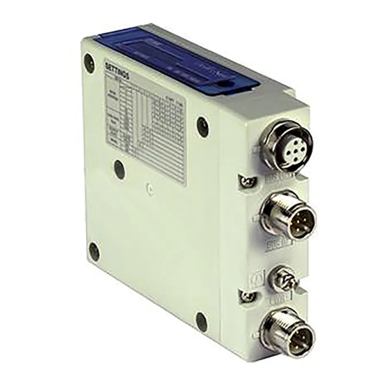
Summary of Product elements <EX260-SDN1/-SDN2/-SDN3/-SDN4> Element Description ∗ 1 DeviceNet connection. Fieldbus interface connector (BUS OUT) (M12 5-pin socket, A-coded) ∗ 1 DeviceNet connection. Fieldbus interface connector (BUS IN) (M12 5-pin plug A-coded) ∗ 1 Power supply with load voltage for valves. Power supply connector (M12 4-pin plug, A-coded) Ground terminal... -
Page 11: Installation And Wiring
Installation and Wiring ■Installation Connect valve manifold to the SI unit. •Dimensions for installation n: number of valve stations 120.7 136.7 152.7 168.7 184.7 200.7 216.7 232.7 248.7 264.7 280.7 296.7 312.7 328.7 344.7 (mm) The above table shows dimensions as an example for the SY5000 series valve manifold. Connectable valve manifolds are the same as for EX250 series SI unit. -
Page 12: Wiring
■Wiring Select the appropriate cables to mate with the connectors mounted on the SI unit. ○Fieldbus interface connector layout The bus connector layout for DeviceNet is as follows. BUS OUT: M12 5-pin socket, A-coded BUS IN: M12 5-pin plug, A-coded Contact layout Designation BUS IN... - Page 13 ○DeviceNet™ communication cable A shielded twisted pair cable for DeviceNet should be used. The max. cable length depends on the transmission speed and the cable type used. <DeviceNet bus cable specification> Thick line Thin line Item Signal Power Signal Power Conductor 0.82 mm 1.65 mm...
- Page 14 ○Power supply connector layout The power supply connector for the solenoid valve voltage is as follows. PWR: M12 4-pin plug, A-coded Designation Contact layout +24 V for solenoid valve 0 V for solenoid valve Power-supply line for solenoid valve and power-supply line for SI unit operation are isolated. Be sure to supply power, respectively.
- Page 15 ○Ground terminal Connect the ground terminal to ground. Resistance to ground should be 100 ohms or less. -14- No.EX##-OMN0013-D...
-
Page 16: Led Indication And Settings
LED Indication and Settings ○LED indication Description Network status. (See the table below for details) SI unit status. (See the table below for details) Turns ON in green when network power is supplied. Turns ON in green when load voltage for the valve is supplied. PWR(V) Turns OFF when load voltage for the valve is not supplied or outside tolerance range. - Page 17 ○Switch setting Set the DeviceNet node address (MAC ID), DeviceNet communication speed and fail safe mode, i.e. reaction of outputs to the communication error, of the SI unit using the 10-element switch. Note 1. To set with switch, use a small blade screwdriver to flip the switches 2.
- Page 18 •HW/SW mode setting (switch No.1) Modifications to the address and speed can be made locally or over the network. Local setting: Hardware mode (referred to as “HW mode”) Network setting: Software mode (referred to as “SW mode”) ∗: Factory default setting is "HW mode". 0: OFF 1: ON Switch No.
- Page 19 •Setting of the reaction of outputs to the communication error 1) Set the value of the following instance/ attribute to 1. Class Instance attribute Description Value 0: Switch setting valid Hold Clear Timeout (SMC) 1: EEPROM set value Valid 2) Set the fault action and fault values in the following instances. There are two types of fault setting method, one is the individual setting per point with the Discrete Output Point (DOP) Object and the other is the batch setting with Assembly Object.
- Page 20 ○Output number assignment Output data ∗: The output number refers to the solenoid position on the manifold and starts at zero. ∗: Standard wiring on the manifold is for double-solenoid valves and output number starts A side and B side in that order as shown in the figure a.
-
Page 21: Devicenet Tm Objects
DeviceNet Objects EX260 SI unit supports the following DeviceNet object classes and device type is Pneumatic Valves. ∗: xxh means hexadecimal number. Class code Object class Identity Message Router DeviceNet Assembly DeviceNet Connection Discrete Output Point Parameter SMC SI (SMC Specific) 1. - Page 22 2. Message Router Object (Class ID: 02h) 2-1. Class attribute Access rule Description Value 2-2. Class common service Service code Description 2-3. Instance attribute Access rule Description Value 2-4. Instance common service Service code Description 2-5. Specific service None. 3. DeviceNet Object (Class ID: 03h) 3-1.
- Page 23 3-4. Instance common service Service code Description Get_Attribute_Single Set_Attribute_Single 3-5. Specific service Service code Description Allocate_Master/Slave_Connection_set Release_Group_2_Identifier_Set 4. Assembly Object (Class ID: 04h) 4-1. Class attribute Access rule Description Value revision 4-2. Class common service Service code Service name 4-3. Instance attribute Access rule Description ∗...
- Page 24 4-5. Vendor specific instance (Fault/Idle package setting/ diagnostic data) Type Description Byte ∗ 1 Output Discrete Output Point Fault Value ∗ 1 Output Discrete Output Point Fault Action ∗ 1 Output Discrete Output Point Idle Value ∗ 1 Output Discrete Output Point Idle Action ∗...
- Page 25 5. DeviceNet Connection Object (Class ID: 05h) 5-1. Class attribute Access rule Description Value 5-2. Class common service Service code Description 5-3. Instance attribute1 (Explicit message) Access rule Description Value State Instance_type TransportClass_trigger DeviceNet _produced_connection_id DeviceNet _consumed_connection_id DeviceNet _initial_comm_characteristics Produced_connection_size FFFFh Consumed_connection_size FFFFh...
- Page 26 5-5. Instance common service Service code Description Get_Attribute_Single Set_Attribute_Single 6. Discrete Output Point Object (Class ID: 09h) 6-1. Class attribute Access rule Description Value Max Instance 6-2. Class common service Service code Description Get_Attribute_Single 6-3. Instance attribute Access rule Description Value 0: OFF Get/Set...
- Page 27 7. Parameter Object (Class ID: 0Fh) 7-1. Class attribute Access rule Description Value Max Instance Parameter Class Descriptor Configuration Assembly Instance 7-2. Class common service Service code Description Get_Attribute_Single 7-3. Instance attribute1: SOLV Status Access rule Description Value 0: Valve power supply voltage is normal Parameter Value 1: Valve power supply voltage is abnormal Link Path Size...
- Page 28 7-6. Instance attribute4: EEPROM Status Access rule Description Value 0: Normal Parameter Value 1: There is a check sum error. 2: Error related to previous write cycle Link Path Size Link Path 20h 64h 24h 01h 30h 6Dh Descriptor Data Type Data Size 7-7.
-
Page 29: Troubleshooting And Maintenance
Troubleshooting and Maintenance ○Troubleshooting chart When any malfunction is observed, it is recommended to perform the following troubleshooting. SI unit SI unit Refer to fault PWR LED and malfunction No.1 MS LED is OFF SI unit Refer to fault PWR(V) LED is OFF No.2 SI unit Refer to fault... - Page 30 Troubleshooting table Fault No.1 Fault Probable cause Recommended error handling Recommended action Re-tighten the DeviceNet cable. (Replace the cable if it is Defective SI unit Check the DeviceNet cable connection. broken) DeviceNet cable PWR LED and MS LED is Correct the DeviceNet power wiring layout.
- Page 31 Fault No.6 Fault Probable cause Recommended error handling Recommended action Check the MAC ID is not duplicated with the Set MAC ID to the SI unit Duplicate MAC ID other slave units. correctly. Check if the communication speed setting on Set same speed setting with the SI unit matches the speed setting on the DeviceNet...
- Page 32 Fault No.9 Fault Probable cause Recommended error handling Recommended action Check if solenoid count does not exceed the allowable number. Group of It depends on SI unit model and valve series. Keep the number of valves not Too many valves mounting solenoid valves working Allowable solenoid number by valve series:...
- Page 33 ○Maintenance Replacement of the SI unit •Remove the M3 hexagon screws from the SI unit and release the SI unit from the valve manifold. •Replace the SI unit. •Tighten the screws with the specified tightening torque. (0.6 Nm) Precautions for maintenance (1) Be sure to switch off the power.
-
Page 34: Specifications
Specifications ■Specifications General specifications Item Specifications Ambient temperature -10 to +50 Ambient humidity 35 to 85%RH (No condensate) Ambient temperature for storage -20 to +60 Withstand voltage 500 VAC applied for 1 minute Insulation resistance 500 VDC, 10 MΩ or more Operating atmosphere No corrosive gas Pollution degree... - Page 35 Network communication specifications Item Specifications DeviceNet Protocol Volume 1 (Edition 3.5) Volume 3 (Edition 1.5) Slave type Group 2 Only Server Device type 1Bh (Pneumatic Valve) 92h: EX260-SDN1 98h: EX260-SDN2 Product code 96h: EX260-SDN3 99h: EX260-SDN4 Vender ID 7h (SMC Corp.) Duplicate MAC ID Check Message Unconnected Explicit Message Applicable message...
-
Page 36: Dimensions
■Dimensions •If a fieldwireable connector is used for the power supply connection, and the SI unit is installed directly to a valve manifold, the connector should be φ16 mm or less. If the connector is a larger diameter it will interfere with the clamping face. Recommended cables are specified in the accessories section, on page 36. -
Page 37: Accessories
Accessories ○Connector cable Compatible connector SI unit connector Description Part number Specifications Manufacturer Communication cable for Connector: M12 straight PCA-1557646 DeviceNet Cable: 5 m Fieldbus Fieldwireable connector for PCA-1557659 Connector: M12 straight interface DeviceNet connector Terminating resistor for (BUS OUT) PCA-1557675 DeviceNet Seal cap... - Page 38 Revision history A: Revise some wording B: Revision C: Revision D: Limited warranty and Disclaimer are added. Note: Specifications are subject to change without prior notice and any obligation on the part of the manufacturer. DeviceNet is a trademark of ODVA. ©...
Need help?
Do you have a question about the EX260 Series and is the answer not in the manual?
Questions and answers