SMC EX260-SEC1, EX260-SEC2, EX260-SEC, EX260-SEC4 - Fieldbus Device Manual
- Operation manual (1 page) ,
- Operation manual (28 pages) ,
- Operation manual (28 pages)
Advertisement
The intended use of this product is to control pneumatic valves and I/O while connected to the EtherCAT protocol.
Safety Instructions
These safety instructions are intended to prevent hazardous situations and/or equipment damage. These instructions indicate the level of potential hazard with the labels of "Caution," "Warning" or "Danger." They are all important notes for safety and must be followed in addition to International Standards (ISO/IEC) *1), and other safety regulations.
*1) ISO 4414: Pneumatic fluid power - General rules relating to systems.
ISO 4413: Hydraulic fluid power - General rules relating to systems.
IEC 60204-1: Safety of machinery - Electrical equipment of machines. (Part 1: General requirements)
ISO 10218-1: Manipulating industrial robots - Safety. etc.
- Refer to product catalogue, Operation Manual and Handling Precautions for SMC Products for additional information.
- Keep this manual in a safe place for future reference.
 | Caution indicates a hazard with a low level of risk which, if not avoided, could result in minor or moderate injury. |
 | Warning indicates a hazard with a medium level of risk which, if not avoided, could result in death or serious injury. |
 | Danger indicates a hazard with a high level of risk which, if not avoided, will result in death or serious injury. |
- Always ensure compliance with relevant safety laws and standards.
- All work must be carried out in a safe manner by a qualified person in compliance with applicable national regulations.
- Provide grounding to assure the safety and noise resistance of the Fieldbus system.
Individual grounding should be provided close to the product using a short cable. - When conformity to UL is required the SI unit must be used with a UL1310 Class 2 power supply.
Specifications
General specifications
| Item | Specifications |
| Ambient temperature | -10 to +50 oC |
| Ambient humidity | 35 to 85%RH (No condensate) |
| Ambient storage temperature | -20 to +60 oC |
| Withstand voltage | 500 VAC applied for 1 minute |
| Insulation resistance | 500 VDC, 10 MΩ or more |
| Operating atmosphere | No corrosive gas |
| Enclosure | IP67 |
| Weight | 200 g or less |
Electrical specifications
| Item | Specifications | ||
| Power supply voltage range / current consumption | Controller power supply | 21.6 to 26.4 VDC 0.1 A max. | |
| Solenoid valve power supply | 22.8 to 26.4 VDC 2.0 A or less, according to the solenoid valve station specification | ||
| Solenoid valve specification | Output type | EX260-SEC1/3 | PNP (negative common) / source |
| EX260-SEC2/4 | NPN (positive common) / sink | ||
| Number of outputs | 32 outputs | ||
| Output condition at the time of communication error | Output CLEAR | ||
| Connected load | Solenoid valve with surge voltage suppressor of 24 VDC and 1.5 W or less (manufactured by SMC) | ||
| Insulation type | Photo coupler | ||
| Residual voltage | 0.4 VDC or less | ||
Communication specifications
| Item | Specifications | |
| Protocol | EtherCAT | |
| EtherCAT mode | Direct Mode (no MAC address) : does not support Open mode : does not support Open mode | |
| Transmission speed | 100 Mbps | |
| Transmission medium | Standard Ethernet cable (CAT5) 100-Base-TX | |
| No. of connected nodes | Up to 65,535 nodes | |
| Network topology | Daisy chain | |
| Max. segment length | Up to 100 m (328 ft) | |
| Address setting | Automatic setting, manual setting not required | |
| Number of outputs | EX260-SEC1/2 | 32 outputs |
| EX260-SEC3/4 | 16 outputs | |
| Vendor ID | 00000114 hex (276) | |
| Product code | EX260-SEC1 | 01000001 hex (16777217) |
| EX260-SEC2 | 01000002 hex (16777218) | |
| EX260-SEC3 | 01000003 hex (16777219) | |
| EX260-SEC4 | 01000004 hex (16777220) | |
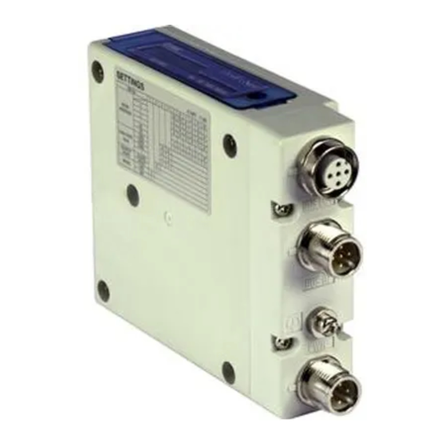
Name and function of parts

| No | Part | Description |
| 1 | Fieldbus connector (BUS OUT) | EtherCAT connection (M12 4-pin socket, D-coded) |
| 2 | Fieldbus connector (BUS IN) | EtherCAT connection (M12 4-pin socket, D-coded) |
| 3 | Power supply connector | Power supply for valves and operation of SI unit (M12 5-pin plug, A-coded) |
| 4 | Ground terminal | Functional Earth (M3) |
| 5 | Output connector | Output signal interface for valve manifold |
| 6 | LED display | Bus status specific and SI unit status LED's |
| 7 | Mounting hole | Mounting hole for connection to the valve manifold |
Installation
Installation
- Do not install the product unless the safety instructions have been read and understood.
- General instructions on installation and maintenance
Connect the valve manifold to the SI unit. - Assembly and disassembly of the SI unit


Replacement of the SI unit
- Remove the M3 hexagon screws from the SI unit and release the SI unit from the valve manifold.
- Replace the SI unit.
- Tighten the screws with the specified tightening torque. (0.6 N•m)
Assembly Precautions
- Be sure to switch off the power.
- Check there is no foreign matter inside the SI unit.
- Check there is no damage and no foreign matter stuck to the gasket.
- Be sure to tighten the screws with the specified torque.
- If the SI unit is not assembled properly, the internal PCBs may be damaged or liquid and/or dust may enter into the unit.
Connecting Cables
Select the appropriate cables to mate with the connectors mounted on the SI unit.
Fieldbus interface connector layout
BUS OUT: M12 4-pin socket, D-coded (SPEEDCON)
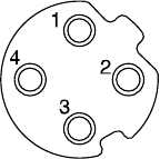
| No. | Designation | Description |
| 1 | TD+ | Transmit Data + |
| 2 | RD+ | Receive Data + |
| 3 | TD- | Transmit Data - |
| 4 | RD- | Receive Data - |
BUS IN: M12 4-pin socket, D-coded (SPEEDCON)
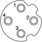
| No. | Designation | Description |
| 1 | TD+ | Transmit Data + |
| 2 | RD+ | Receive Data + |
| 3 | TD- | Transmit Data - |
| 4 | RD- | Receive Data - |
Power supply connector layout
PWR: M12 5-pin plug, A-coded (SPEEDCON)

| No. | Designation | Description |
| 1 | SV24V | +24 V for solenoid valve |
| 2 | SV0V | 0 V for solenoid valve |
| 3 | SI24V | +24 V for SI unit operation |
| 4 | SI0V | 0 V for SI unit operation |
| 5 | - | Not used |
- The power supply for the solenoid valve and SI unit operation are isolated. Be sure to supply power respectively.
Either single source power or two different power supplies can be used.
NOTE
When conformity to UL is required the SI unit must be used with a UL1310 Class 2 power supply.
The M12 connector cable for fieldbus and power supply connections has two types, Standard M12 and SPEEDCON compatible. If both plug and socket have SPEEDCON connectors, the cable can be inserted and connected by turning it a 1/2 of a rotation, leading to a reduction in man hours.
A standard connector can be connected to a SPEEDCON connector.
- Be sure to fit a seal cap (EX9-AWTS) on any unused connectors. Proper use of the seal cap enables the enclosure to maintain IP67 specification.
Ground Terminal
- Connect the ground terminal to ground.
- Individual grounding should be provided close to the product with a short cable to assure the safety and noise resistance of the Fieldbus system.
- Resistance to ground should be 100 ohms or less.
Environment
- Do not use in an environment where corrosive gases, chemicals, salt water or steam are present.
- Do not install in a location subject to vibration or impact in excess of the product's specifications.
Setting
Configuration
- Auto-increment addressing can be used to address each slave device according to its physical position in the communication ring and does not require local manual address setting.
- To configure the EX260 SI unit with the EtherCAT master, an XML Device Description File is required.
- Technical documentation giving detailed configuration information and the XML file can be found on the SMC website (URL: https://www.smcworld.com)
Output number assignment
Output numbering starts at zero and refers to the solenoid position on the manifold.

How to Order
Refer to the operation manual on the SMC website (URL: https://www.smcworld.com) for How to order information.
Outline Dimensions (mm)
Refer to the operation manual on the SMC website (URL: https://www.smcworld.com) for outline dimensions.
Maintenance
General Maintenance
- Not following proper maintenance procedures could cause the product to malfunction and lead to equipment damage.
- If handled improperly, compressed air can be dangerous.
- Maintenance of pneumatic systems should be performed only by qualified personnel.
- Before performing maintenance, turn off the power supply and be sure to cut off the supply pressure. Confirm that the air is released to atmosphere.
- After installation and maintenance, apply operating pressure and power to the equipment and perform appropriate functional and leakage tests to make sure the equipment is installed correctly.
- If any electrical connections are disturbed during maintenance, ensure they are reconnected correctly and safety checks are carried out as required to ensure continued compliance with applicable national regulations.
- Do not make any modification to the product.
- Do not disassemble the product, unless required by installation or maintenance instructions
- Stop operation if the product does not function correctly.
LED Display

| LED | Status | Description |
| RUN | OFF | INIT |
| Green Flashing | PRE-OPERATIONAL | |
| Green Single Flash | SAFE-OPERATIONAL | |
| Green Flickering | BOOTSTRAP | |
| Green ON | OPERATIONAL | |
| L/A IN | OFF | BUS IN: No Link, No Activity |
| Green ON | BUS IN: Link, No Activity | |
| Green Flickering | BUS IN: Link, Activity | |
| L/A OUT | OFF | BUS OUT: No Link, No Activity |
| Green ON | BUS OUT: Link, No Activity | |
| Green Flickering | BUS OUT: Link, Activity | |
| PWR | Green ON | SI unit operating voltage supplied |
| OFF | SI unit operating voltage not supplied | |
| PWR(V) | Green ON | Load voltage for valves supplied |
| OFF | Load voltage for valves not supplied or outside tolerance range (19 V or less) |

Limitations of Use
Limited warranty and Disclaimer/Compliance Requirements
Refer to Handling Precautions for SMC Products.
Product Disposal
This product shall not be disposed of as municipal waste. Check your local regulations and guidelines to dispose this product correctly, in order to reduce the impact on human health and the environment.
Contacts
Refer to www.smcworld.com or www.smc.eu for your local distributor / importer.
SMC Corporation
URL: https://www.smcworld.com (Global) https://www.smc.eu (Europe)
SMC Corporation, 4-14-1, Sotokanda, Chiyoda-ku, Tokyo 101-0021, Japan
Specifications are subject to change without prior notice from the manufacturer.
© 2021 SMC Corporation All Rights Reserved.

Documents / Resources
References
Download manual
Here you can download full pdf version of manual, it may contain additional safety instructions, warranty information, FCC rules, etc.
Download SMC EX260-SEC1, EX260-SEC2, EX260-SEC, EX260-SEC4 - Fieldbus Device Manual
Advertisement


Need help?
Do you have a question about the EX260-SEC1 and is the answer not in the manual?
Questions and answers