SMC Networks EX260 Series Operation Manual
Si unit for ethercat
Hide thumbs
Also See for EX260 Series:
- Operation manual (39 pages) ,
- Operation manual (28 pages) ,
- Operation manual (37 pages)

Related Manuals for SMC Networks EX260 Series


Summary of Contents for SMC Networks EX260 Series
- Page 1 No.EX##-OMN0011-B PRODUCT NAME SI unit for EtherCAT MODEL / Series / Product Number EX260 Series...
-
Page 2: Table Of Contents
Contents Safety Instructions How to Order Summary of Product elements Installation and Cabling Installation Connecting cables LED indication and Settings Troubleshooting and Maintenance Specifications Table of Specifications Dimensions Accessories No.EX##-OMN0011-B... -
Page 3: Safety Instructions
Safety Instructions These safety instructions are intended to prevent hazardous situations and/or equipment damage. These instructions indicate the level of potential hazard with the labels of "Caution", "Warning" or "Danger". They are all important notes for safety and must be followed in addition to International ∗... - Page 4 Caution The product is provided for use in manufacturing industries. The product herein described is basically provided for peaceful use in manufacturing industries. If considering using the product in other industries, consult SMC beforehand and exchange specifications or a contract if necessary. If anything is unclear, contact your nearest sales branch.
- Page 5 Operator ♦This operation manual is intended for those who have knowledge of machinery using pneumatic equipment, and have sufficient knowledge of assembly, operation and maintenance of such equipment. Only those persons are allowed to perform assembly, operation and maintenance. ♦Read and understand this operation manual carefully before assembling, operating or providing maintenance to the product.
- Page 6 ■NOTE ○Follow the instructions given below when designing, selecting and handling the product. •The instructions on design and selection (installation, wiring, environment, adjustment, operation, described below must also be followed. maintenance, etc.) ∗Product specifications •When conformity to UL is necessary the SI unit must be used with a UL1310 Class2 power supply. •The SI unit is a approved product only if they have a mark on the body.
- Page 7 ∗Environment •Select the proper type of protection according to the environment of operation. IP67 protection is achieved when the following conditions are met. (1) The units are connected properly with fieldbus cable with M12 connector and power cable with M12 (M8) connector.
-
Page 8: How To Order
How to Order EX260-SEC 1 Connector type, output specification M12 connector, 32 outputs, source / PNP (negative common) M12 connector, 32 outputs, sink / NPN (positive common) M12 connector, 16 outputs, source / PNP (negative common) M12 connector, 16 outputs, sink / NPN (positive common) Fieldbus EtherCAT ... -
Page 9: Summary Of Product Elements
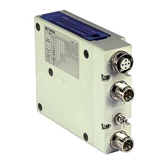
Summary of Product elements <EX260-SEC1/-SEC2/-SEC3/-SEC4> Element Description Fieldbus interface connector ∗ 1 EtherCAT connection (M12 4-pin socket, D-coded) (BUS OUT) Fieldbus interface connector ∗ 1 EtherCAT connection (M12 4-pin socket, D-coded) (BUS IN) ∗ 1 Power supply with load voltage for valves and operating voltage for SI unit Power supply connector (M12 5-pin plug, A-coded) Ground terminal... -
Page 10: Installation And Cabling
Installation and Cabling ■Installation Connect valve manifold to the SI unit. ●Dimensions for installation n: number of valve stations L 1 2 3 4 5 6 7 8 L1 120.7 136.7 152.7 168.7 184.7 200.7 216.7 L2 80 96 112 128 144 160 176 L 9 10 11 12 13 ... -
Page 11: Connecting Cables
■Connecting cables Select the appropriate cables to mate with the connectors mounted on the SI unit. ○Fieldbus interface connector layout BUS OUT: M12 4-pin socket, D-coded Designation Description Transmit Data + Receive Data + Transmit Data - Receive Data - BUS IN: M12 4-pin socket, D-coded Designation Description... - Page 12 ○Power supply connector layout PWR: M12 5-pin plug, A-coded Designation Description SV24 V +24 V for solenoid valve SV0 V 0 V for solenoid valve SI24 V +24 V for SI unit operation SI0 V 0 V for SI unit operation Unused Power-supply line for solenoid valve and power-supply line for SI unit operation are isolated.
- Page 13 ○Ground terminal Connect the ground terminal to ground. Resistance to ground should be 100 ohms or less. -12- No.EX##-OMN0011-B...
-
Page 14: Led Indication And Settings
LED indication and Settings ○LED indication LED Status Description INIT ∗ 1 Green Blinking PRE-OPERATIONAL ∗ 2 Green single flash SAFE-OPERATIONAL ∗ 3 Green flickering BOOTSTRAP Green ON OPERATIONAL BUS IN side: No Link, No Activity Green ON L/A IN BUS IN side: Link, No Activity ∗... - Page 15 ○Configuration Auto-increment addressing can be used address each slave device according to its physical position in the communication ring, and does not require local address setting. To configure the EX260 SI unit with the EtherCAT master, an XML Device Description File is required. The technical document giving detailed configuration information and the XML file can be found on the SMC website (URL http://www.smcworld.com).
- Page 16 OK button. ∗: If EX260 Series SI unit is not found in the list, confirm whether the XML file of this unit is in the [¥TwinCAT¥Io¥EtherCAT] folder, and start up [TwinCAT( System Manager] again 2-1-5.
- Page 17 2-2. On-line Auto Configuration 2-2-1. Connect the unit to the network and apply the power. Then right click the [I/O Devices] file and select [Scan Devices]. 2-2-2. When the comment “Scan for boxes” appears, click the [YES(Y)] button. Once the scan is completed correctly, the products that are connected to the network are displayed as shown below.
- Page 18 ○Output number assignment Output data Output layout of the 32 outputs type Output layout of the 16 outputs type (Example of EX260-SEC1) (Example of EX260-SEC3) ・・・Byte unit ・・・Byte unit Bit unit Bit unit -17- No.EX##-OMN0011-B...
- Page 19 ∗: The output number refers to the solenoid position on the manifold and starts at zero. ∗: Standard wiring on the manifold is for double-solenoid valves and output number starts A side and B side in that order as shown in the figure a.
-
Page 20: Troubleshooting And Maintenance
Troubleshooting and Maintenance ○Troubleshooting chart When any malfunction is observed, it is recommended to perform the following troubleshooting. SI unit SI unit Refer to fault PWR LED OFF malfunction No.1 SI unit Refer to fault PWR (V) LED OFF No.2 SI unit Refer to fault L/A IN LED OFF... - Page 21 Troubleshooting table Fault No.1 Fault Probable cause Recommended error handling Recommended action Re-tighten the power cable. (Replace the cable if it is Defective power Check the condition of the power cable broken) cable wiring for SI wiring to the SI unit. SI unit unit operation Correct the power cable wiring...
- Page 22 Fault No.5 Fault Probable cause Recommended error handling Recommended action Configure the SI unit by the EtherCAT master using the Check that the EtherCAT master SI unit SI unit is in INIT valid XML file. configuration setup for the SI unit matches RUN LED off state the actual set up of the SI unit.
- Page 23 ○Maintenance Replacement of the SI unit •Remove the M3 hexagon screws from the SI unit and release the SI unit from the valve manifold. •Replace the SI unit. •Tighten the screws with the specified tightening torque. (0.6 Nm) Precautions for maintenance (1) Be sure to switch off the power.
-
Page 24: Specifications
Specifications ■Table of Specifications General specifications Item Specifications Ambient temperature -10 to +50 Ambient humidity 35 to 85%RH (No condensate) Ambient temperature for storage -20 to +60 Withstand voltage 500 VAC applied for 1 minute Insulation resistance 500 VDC, 10 MΩ or more Operating atmosphere No corrosive gas Pollution degree... - Page 25 Network communication specifications Item Specifications Protocol EtherCAT Direct Mode (No MAC address) EtherCAT mode ∗: Does not support Open Mode. Transmission speed 100 Mbps Transmission medium Standard Ethernet cable (CAT5) (100BASE-TX) Number of nodes connected (Up to 65,535 nodes.) Network topology Daisy chain Maximum segment length Up to 100 m (328 ft)
-
Page 26: Dimensions
Dimensions -25- No.EX##-OMN0011-B... -
Page 27: Accessories
Accessories ○Connector cable Compatible connector SI unit connector Description Part number Specifications Manufacturer Connector: M12 straight PCA-1446566 Cable: 5 m Cable with Connector: M12 straight at communication Fieldbus interface EX9-AC020EN one end and RJ45 connector connector -PSRJ at the other end (BUS OUT) Cable: 2 m Fieldwireable... - Page 28 Revision history A: Revise some wording B: Revision Note: Specifications are subject to change without prior notice and any obligation on the part of the manufacturer. EtherCAT is registered trademark and patented technology, licensed by Beckhoff Automation GmbH, Germany. ...
Need help?
Do you have a question about the EX260 Series and is the answer not in the manual?
Questions and answers