
Subscribe to Our Youtube Channel
Related Manuals for SMC Networks EX260-SIL1 series


Summary of Contents for SMC Networks EX260-SIL1 series
- Page 1 No.EX※※-OMW0016 PRODUCT NAME SI unit device) MODEL / Series / Product Number EX260-SIL1...
-
Page 2: Table Of Contents
Table of Contents Safety Instructions Model Indication and How to Order Summary of Product elements Summary of product function Installation and Wiring Installation Wiring LED Indication, Settings and Status Monitoring LED indication Switch setting (Process data size / Data transmission rate setting) Parameter settings and status monitoring IODD file Data Storage... -
Page 3: Safety Instructions
Safety Instructions These safety instructions are intended to prevent hazardous situations and/or equipment damage. These instructions indicate the level of potential hazard with the labels of "Caution", "Warning" or "Danger". They are all important notes for safety and must be followed in addition to International Standards (ISO/IEC) , and other safety regulations. - Page 4 Safety Instructions Caution 1.The product is provided for use in manufacturing industries. The product herein described is basically provided for peaceful use in manufacturing industries. If considering using the product in other industries, consult SMC beforehand and exchange specifications or a contract if necessary. If anything is unclear, contact your nearest sales branch.
- Page 5 Operator This operation manual is intended for those who have knowledge of machinery using pneumatic equipment, and have sufficient knowledge of assembly, operation and maintenance of such equipment. Only those persons are allowed to perform assembly, operation and maintenance. Read and understand this operation manual carefully before assembling, operating or providing maintenance to the product.
- Page 6 ■NOTE Follow the instructions given below when designing, selecting and handling the product. The instructions on design and selection (installation, wiring, environment, adjustment, operation, described below must also be followed. maintenance, etc.) Product specifications •When conformity to UL is required, the SI unit should be used with a UL1310 Class 2 power supply. •The SI unit is a UL approved product only if they have a mark on the body.
- Page 7 Product handling Installation •Do not drop, hit or apply excessive shock to the fieldbus system. Otherwise damage to the product can result, causing malfunction. •Tighten to the specified tightening torque. If the tightening torque is exceeded the mounting screws may be broken. IP67 protection cannot be guaranteed if the screws are not tightened to the specified torque.
- Page 8 •Mount the product in a place that is not exposed to vibration or impact. Otherwise failure or malfunction can result. •Do not use the product in an environment that is exposed to temperature cycle. Heat cycles other than ordinary changes in temperature can adversely affect the inside of the product. •Do not expose the product to direct sunlight.
-
Page 9: Model Indication And How To Order
Model Indication and How to Order EX260-SIL 1 Connector type, output specification M12 connector, 32 outputs, PNP (negative common) / source Fieldbus IO-Link : IO-Link is the first standardized IO technology worldwide (IEC 61131-9) for the communication with sensors and also actuators and it is being disseminated under a dedicated word mark/logo, No.EX※※-OMW0016... -
Page 10: Summary Of Product Elements
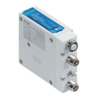
Summary of Product elements Element Description IO-Link communication/ IO-Link communication interface for connection (Port Class B) including power supply connector power supply for solenoid valves (M12 5-pin plug, A-coded) Ground terminal Functional earth (M3 screw) Output connector Output signal interface for solenoid valve manifold ... -
Page 11: Summary Of Product Function
■Summary of product function I/O function This device can control 32 outputs for solenoid valve control and check device status using cyclic data communication via IO-Link system. Fault action Output action at a communication fault can be set by parameter, either Clear Output, Force Output or Hold Last State. -
Page 12: Installation And Wiring
Installation and Wiring ■Installation Connect solenoid valve manifold to the SI unit. Dimensions for installation n: number of solenoid valve stations 120.7 136.7 152.7 168.7 184.7 200.7 216.7 232.7 248.7 264.7 280.7 296.7 312.7 328.7 344.7 (mm) The above table shows dimensions as an example for the SY5000 series solenoid valve manifold. -11- No.EX※※-OMW0016... -
Page 13: Wiring
■Wiring Select the appropriate cables to mate with the connectors mounted on the SI unit. IO-Link communication and power supply connector layout (Port Class B) BUS IN: M12 5-pin plug, A-coded Designation Description +24 V for SI unit SV24 V +24 V for solenoid valve 0 V for SI unit IO-Link communication line... -
Page 14: Led Indication, Settings And Status Monitoring
LED Indication, Settings and Status Monitoring ■LED indication LED Status Description Green ON Power ON, IO-Link communication inactive Green OFF Power OFF Flashing Green IO-Link communication active Green ON Power for the solenoid valve is supplied PWR(V) Power for the solenoid valve is not supplied or outside the tolerance range (19 V or less) ■Switch setting (Process data size / Data transmission rate setting) The switch should only be set with the power supply turned off. -
Page 15: Parameter Settings And Status Monitoring
■Parameter settings and status monitoring IODD file An IODD (I/O Device Description) is a file that provides all the necessary properties to establish communication and the necessary parameters and their boundaries to establish the desired function of a sensor or actuator. It is the set of files of the main IODD file and image files such as a vendor logo, device picture and device icon. - Page 16 ISDU Parameters ISDU Data Access Parameter Name Storage Value Index 1 Sub-Index 2 (dec) Refer to page "Coding 0x0002 SystemCommand of System Command" for details 0x000C Refer to page "Device Device Access Locks (12) Access Locks" for details 0x0010 Vendor Name SMC Corporation (16) 0x0011...
-
Page 17: Parameter Data
Coding of SystemCommand (index 2) For ParamDownloadStore, Device reset, Application reset, Restore factory settings or Output switching count value reset, the ISDU Index 0x002 (SystemCommand) should be used. The buttons, a command interface to the SI unit, labelled with the following command name (except ParamDownloadStore) are displayed in the IO-Link Tool. - Page 18 Device Access Locks (index 12) For Device Access Locks, the following Device locking possibilities are specified. Value Definition unlocked parameter (write) access locked data storage locked parameter (write) access locked and data storage locked Parameter (write) access: If the "Parameter (write) access" bit is set in the SI unit, write access to all SI unit parameters over the IO-Link communication is inhibited for all read/write parameters of the SI unit except the parameter Device Access Locks.
- Page 19 Application Specific Parameters Data Index Sub- Access Data Parameter name Default Storage Description 1 (dec) index type 2 Determine how the SI unit output act when a IO-Link communication fault 0x54 Output Fault (individual setting from 1,2,3,4 {0,0,0,0} (84) Action OUT0 to OUT31) 0: Output Fault Value parameter setting value...
- Page 20 Application Specific Parameters (continue) Data Index Sub- Access Data Parameter name Default Storage Description 1 (dec) index type 2 Output status for short circuit 0x58 Output Short (individual status from 1,2,3,4 {0,0,0,0} (88) Circuit Status OUT0 to OUT31) 0: normal 1: short circuit Set count threshold of output switching count...
- Page 21 Structure of Output Fault Action / Output Fault Value Parameter (index 84, 85) Set the output (output 0 to output 31) at a IO-Link communication fault with two indexes. For each output assignment, bit 0 corresponds to output 0 and bit 1 corresponds to output 1 by sub index. Set the values below 2 bits for all outputs.
- Page 22 Structure of Output Open Circuit Detection Parameter (index 86) Determine enable/disable of the open circuit detecting function of each output (output 0 to output 31) by four 8-bit long sub-index. Bit 0 in the bit field corresponds to Output 0, Bit 1 to Output 1 and so on. An example of setting is shown below.
- Page 23 Structure of Output Switching Counts Set Point (index76) Set count threshold of output switching count of each output (output 0 to output 31) with 32 bit length respectively. Sub index 1 corresponds to output 0, sub index 2 corresponds to output 1 and so on. For each output, the threshold can be set up to 4,294,967,295 (0xFFFFFFFF).
-
Page 24: Output Number Layout / Process Data
■Output number layout / Process data The process data of this product is designed with byte array base data type, so the byte order when solenoid output is allocated on the PLC memory is based on the endian type of the transmission format of the IO-Link master gateway upper communication, either big endian format or little endian format. - Page 25 For the fieldbus / Industrial Ethernet with the little endian transmission format (e.g. EtherNet/IP, EtherCAT, CC-Link IE) -24- No.EX※※-OMW0016...
- Page 26 The output numbering refers to the solenoid position on the manifold and starts at zero. Standard wiring of the manifold is for a double-solenoid valve. The output number starts at the A side and then B side in that order as shown in figure a.
-
Page 27: Input Number Layout / Process Data
■Input number layout / Process data In this product, Device Status can be added to input data by the switch setting (Page 13). (Refer to the table below) Bit offset Index 36 (Device Status) value Status definition Details In normal operation Maintenance Output switching counter value over-run... -
Page 28: Troubleshooting And Maintenance
Troubleshooting and Maintenance ○Troubleshooting chart When any malfunction is observed, it is recommended to perform the following troubleshooting. SI unit SI unit Refer to fault malfunction COM LED is OFF No.1 SI unit Refer to fault PWR (V) LED is OFF No.2 SI unit COM LED Refer to fault... - Page 29 ○Troubleshooting table Fault No.1 Fault Probable cause Recommended error handling Recommended action Re-tighten the IO-Link cable. Defective IO-Link (Replace the cable if it is broken) Check the condition of the IO-Link cable cable wiring for SI wiring to the SI unit. Correct the IO-Link cable wiring unit operation layout.
- Page 30 Fault No.4 Fault Probable cause Recommended error handling Recommended action If the inspection level of the Master port in Connect the SI unit with a which the SI unit is connected is Device ID that matches the ID TYPE_COMP, Check the Device ID of the Master port has configured in the Master port.
- Page 31 Fault No.7 Fault Probable cause Recommended error handling Recommended action Tighten the screws with the Poor connection Check if there are any loose screws making specified tightening torque between SI unit and the connection between the SI unit and the (i.e.
- Page 32 ■Maintenance Replacement of the SI unit •Remove the M3 hexagon screws from the SI unit and release the SI unit from the solenoid valve manifold. •Replace the SI unit. •Tighten the screws with the specified tightening torque. (0.6 Nm) Precautions for maintenance (1) Be sure to switch off the power.
-
Page 33: Specification
Specification ■Specifications General specifications Item Specifications Ambient temperature -10 to +50 Ambient humidity 35 to 85%RH (No condensate) Ambient temperature for storage -20 to +60 Withstand voltage 500 VAC applied for 1 minute Insulation resistance 500 VDC, 10 MΩ or more Operating atmosphere No corrosive gas Enclosure... - Page 34 IO-Link communication specifications Item Specifications Protocol IO-Link version 1.1 Data transmission rate 230.4 Kbps (COM3) or 38.4 kbps (COM2) selectable EX260-SIL1 0.8 ms (in/out 0/4 bytes, COM3) EX260-SIL1 3.4 ms (in/out 0/4 bytes, COM2) Process data minimum cycle time EX260-SIL1 1 ms (in/out 2/4 bytes, COM3) EX260-SIL1...
-
Page 35: Dimensions
■Dimensions •If a fieldwireable connector is used for the power supply connection, and the SI unit is installed directly to a solenoid valve manifold, the connector should be 16 mm or less. If the connector is a larger diameter it will interfere with the clamping face. -34- No.EX※※-OMW0016... - Page 36 Revision history 4-14-1, Sotokanda, Chiyoda-ku, Tokyo 101-0021 JAPAN Tel: + 81 3 5207 8249 Fax: +81 3 5298 5362 http://www.smcworld.com Note: Specifications are subject to change without prior notice and any obligation on the part of the manufacturer. © 2019 SMC Corporation All Rights Reserved No.EX※※-OMW0016...
Need help?
Do you have a question about the EX260-SIL1 series and is the answer not in the manual?
Questions and answers