
Related Manuals for SMC Networks EX250-SPR1


Summary of Contents for SMC Networks EX250-SPR1
- Page 1 No.EX※※-OME0014-F PRODUCT NAME Fieldbus system (SI unit – PROFIBUS DP compatible) MODEL / Series / Product Number EX250-SPR1...
-
Page 2: Table Of Contents
Table of Contents Safety Instructions Model Indication and How to Order Summary of Product Parts Mounting and Installation Installation Wiring Setting Troubleshooting Specification Specifications Dimensions No.EX※※-OME0014-F... -
Page 3: Safety Instructions
Safety Instructions These safety instructions are intended to prevent hazardous situations and/or equipment damage. These instructions indicate the level of potential hazard with the labels of "Caution", "Warning" or "Danger". They are all important notes for safety and must be followed in addition to International 1) standards (ISO/IEC) and other safety regulations. - Page 4 Caution The product is provided for use in manufacturing industries. The product herein described is basically provided for peaceful use in manufacturing industries. If considering using the product in other industries, consult SMC beforehand and exchange specifications or a contract if necessary. If anything is unclear, contact your nearest sales branch.
- Page 5 Operator This operation manual is intended for those who have knowledge of machinery using pneumatic equipment, and have sufficient knowledge of assembly, operation and maintenance of such equipment. Only those persons are allowed to perform assembly, operation and maintenance. Read and understand this operation manual carefully before assembling, operating or providing maintenance to the product.
- Page 6 ■NOTE ○Follow the instructions given below when designing, selecting and handling the product. The instructions on design and selection (installation, wiring, environment, adjustment, operation, described below must also be followed. maintenance, etc.) Product specifications •When conformity to UL is required, the SI unit should be used with a UL1310 Class 2 power supply. The SI unit is a UL approved product only if it has a UL mark on the body.
- Page 7 Product handling Installation •Do not drop, hit or apply excessive shock to the SI unit. Otherwise damage to the product can result, causing malfunction. •Tighten to the specified tightening torque. If the tightening torque is exceeded the mounting screws may be broken. IP67 protection cannot be guaranteed if the screws are not tightened to the specified torque.
- Page 8 •Mount the product in a place that is not exposed to vibration or impact. Otherwise failure or malfunction can result. •Do not use the product in an environment that is exposed to temperature cycle. Heat cycles other than ordinary changes in temperature can adversely affect the inside of the product. •Do not expose the product to direct sunlight.
-
Page 9: Model Indication And How To Order
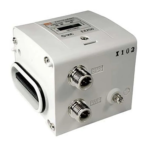
Model Indication and How to Order EX250-SPR1 Communication protocol PROFIBUS DP Summary of Product Parts Element Description 1 Communication connector Connect with PROFIBUS DP communication line. Supplies power to the solenoid valve, the Output block, SI unit and the Input Power supply connector ... -
Page 10: Mounting And Installation
Mounting and Installation ■Installation Not having mounting hole, it can’t be set to BUS independently. Be sure to connect manifold to SI unit for setting. And if Input block is unnecessary, connect End plate directly to SI unit. : The size when connecting Bus Tee with the SI unit directly. For example, the table below shows the size when manifold of VQC1000 series connected. -
Page 11: Wiring
Internal circuit ■Wiring Communication wiring Cable: Shielded twisted pair cable (Type-A cable) Impedance 135 to 165 ohm(3 to 20 MHz) Capacity between conductors 30 pF/m or less Conductor resistance 110 Ω/km or less Cable diameter 0.64 mm or more Conductor area 0.34 mm or more Transmission speed &... - Page 12 Terminator It is necessary to attach bus terminator resistance to the units located at the ends of transmission line. : Contact each manufacture about Communication cable and Bus Tee. -11- No.EX※※-OME0014-F...
- Page 13 Power supply wiring Power supply line inside the unit has individual power supplies for solenoid valve actuation (SV power supply) and for Control parts and Input block (SI SW power supply). Supply 24 VDC for each of them. Either single or dual power supply is available. : In case of single power supply, pay attention to the range of each supply voltage.
- Page 14 Communication connector M12 5-pin reverse (Socket) Example of connected Bus Tee: TURCK VB2/FSW/FKW/FSW45 etc. Pin No. Description Function Supply voltage for Terming Resistor Minus to send/receive data DGND Ground for Terminating Resistor Plus to send/receive data N.C. Unused Power supply connector M12 5-pin (Plug) Example of connected cable: SMC EX500-AP00-S etc.
- Page 15 ○Maintenance Addition of Input Block Remove screws from End Plate. Mount attached tie rod. Connect additional Input Block. Connect End Plate and tighten removed screws by specified tightening torque. (0.6 Nm) Exchange of SI unit Remove screws from End Plate and release connection of each unit. Replace old SI unit with new one.
-
Page 16: Setting
Setting LED display Indication Contents Green lights up when power supply for solenoid valves is turned on. PWR(V) Disappear when solenoid valve power supply voltage decreases below 19V. Green lights up during operation(when power supply for SI unit is turned on.) Red lights up when some failure is detected by self-diagnosis. - Page 17 Diagnosis information Diagnosis information of the SI unit is composed of 6 bytes standard diagnosis information and 7 bytes SI unit status information, 13 bytes in total, as specified in PROFIBUS DP. When the SI unit is in a non-standard state, it will send an error message to the master as diagnosis information, and light up the DIA display.
- Page 18 Byte1: Station Status 2 Bit 7 Diag. Deactivated Diag. Prm_Req “1” when SI unit is stopped “1” when the SI unit setting is rewritten by the master Reserved Diag. Stat_Diag “1” when it has a diagnosis Diag. Sync_Mode “1” when Sync command is received Diag.
- Page 19 (3) Open “View” – “Catalog”, and check that the “Valves” icon has been added to “PROFIBUS DP” – “Additional Field Devices”. Drag and drop “EX250-SPR1(HW)” (file for hardware setting mode) or “EX250-SPR1(SW)” (file for software setting mode)to add it to the PROFIBUS DP line.
- Page 20 I/O Configuration I/O configuration of SI unit is shown below. (Refer to manuals or other information of master for details such as definition of numbers.) Byte (Slot) Type Length Unit 163 (A3H) Output Byte 147 (93H) Input Byte -19- No.EX※※-OME0014-F...
- Page 21 Assignment of I/O No. Correspondence between output data and valve manifold : Output numbers are assigned to stations from side D to U of manifold in order. (See manual of each valve manifold for the directions of side D and U) : Standard manifold is wired in double.
- Page 22 Correspondence between input data and input block : Input numbers are assigned to stations from SI unit side to input side in order. : Each bit of data read into master 4 bytes shows ON/OFF of sensor connected to input block. Starting from LSB of first byte (Offset 0), input numbers are assigned to all bits in numeric order.
-
Page 23: Troubleshooting
Troubleshooting Troubleshooting flow chart If the SI unit malfunctions, select the specific trouble with the flow chart stated below. A reduced wiring system does not operate normally A solenoids valve Only the solenoid Refer to trouble does not operate valve LED turns on No.1 normally The outputs that... - Page 24 Troubleshooting table Trouble No.1 Trouble Possible cause Investigation method of cause Remedy Only the Check the troubleshooting for the solenoid solenoid valve Solenoid valve failure. Same as left. valve. LED turn on. Trouble No.2 Trouble Possible cause Investigation method of cause Remedy The outputs Inadequate total...
- Page 25 Trouble No.3 Trouble Possible cause Investigation method of cause Remedy Check that the power supply cable for the Review the connection solenoid valve is not broken, and that the condition of the power supply Incorrect wiring for the connection between the power supply cable cable.
- Page 26 Trouble No.4 Trouble Possible cause Investigation method of cause Remedy The inputs that Inadequate total Eliminate extra unused are beyond the number of inputs from Check if the total number of inputs is 32 or inputs from the manifold to maximum the Input block less.
- Page 27 Trouble No.7 Trouble Possible cause Investigation method of cause Remedy Incorrect wiring of the Confirm there is no incorrect connection Review the connection power supply for between input and SI unit controlling part condition of the power supply control and input power supply and SI unit power supply cable.
- Page 28 Trouble No.9 Trouble Possible cause Investigation method of cause Remedy Check supply voltage of the solenoid valve power supply. (Information about the Decreased power solenoid valve power supply is sent to the Supply 24 VDC +10%/-5% to supply voltage for PLC as extended diagnostic information.) the power supply for the solenoid valves.
-
Page 29: Specification
Specification ■Specifications General specification Item Specification Operating ambient temp. -10 to +50 Operating ambient humidity 35 to 85%RH (No dew condensation) Storage ambient temp. -20 to +60 Withstand voltage 500 VAC for 1 min. Insulation resistance 500 VDC 10 MΩ or more Operating environment No corrosive gas Pollution degree... -
Page 30: Dimensions
Dimensions -29- No.EX※※-OME0014-F... - Page 31 Revision history A: Add some contents B: Correct an error in writing C: Make an overall revision D: Correct an error in writing E: Revision F: Correct an error in writing Note: Specifications are subject to change without prior notice and any obligation on the part of the manufacturer. ©...
Need help?
Do you have a question about the EX250-SPR1 and is the answer not in the manual?
Questions and answers