SMC Networks EX260 Series Operation Manual
Hide thumbs
Also See for EX260 Series:
- Operation manual (39 pages) ,
- Operation manual (28 pages) ,
- Operation manual (1 page)

Related Manuals for SMC Networks EX260 Series


Summary of Contents for SMC Networks EX260 Series
- Page 1 No.EX##-OMN0009-E PRODUCT NAME SI unit for PROFIBUS DP MODEL / Series / Product Number EX260 Series...
-
Page 2: Table Of Contents
Table of Contents Safety Instructions Model Indication and How to Order Summary of Product elements Installation and Wiring Installation Wiring LED Indication and Settings Troubleshooting and Maintenance Specifications Specifications Dimensions Accessories No.EX##-OMN0009-E... -
Page 3: Safety Instructions
Safety Instructions These safety instructions are intended to prevent hazardous situations and/or equipment damage. These instructions indicate the level of potential hazard with the labels of "Caution", "Warning" or "Danger". They are all important notes for safety and must be followed in addition to International 1) standards (ISO/IEC) and other safety regulations. - Page 4 Caution The product is provided for use in manufacturing industries. The product herein described is basically provided for peaceful use in manufacturing industries. If considering using the product in other industries, consult SMC beforehand and exchange specifications or a contract if necessary. If anything is unclear, contact your nearest sales branch.
- Page 5 Operator This operation manual is intended for those who have knowledge of machinery using pneumatic equipment, and have sufficient knowledge of assembly, operation and maintenance of such equipment. Only those persons are allowed to perform assembly, operation and maintenance. Read and understand this operation manual carefully before assembling, operating or providing maintenance to the product.
- Page 6 ■NOTE ○Follow the instructions given below when designing, selecting and handling the product. The instructions on design and selection (installation, wiring, environment, adjustment, operation, described below must also be followed. maintenance, etc.) Product specifications •When conformity to UL is required, the SI unit should be used with a UL1310 Class 2 power supply. •The SI unit is a UL approved product only if they have a mark on the body.
- Page 7 Product handling Installation •Do not drop, hit or apply excessive shock to the fieldbus system. Otherwise damage to the product can result, causing malfunction. •Tighten to the specified tightening torque. If the tightening torque is exceeded the mounting screws may be broken. IP67 protection cannot be guaranteed if the screws are not tightened to the specified torque.
- Page 8 •Mount the product in a place that is not exposed to vibration or impact. Otherwise failure or malfunction can result. •Do not use the product in an environment that is exposed to temperature cycle. Heat cycles other than ordinary changes in temperature can adversely affect the inside of the product. •Do not expose the product to direct sunlight.
-
Page 9: Model Indication And How To Order
Model Indication and How to Order EX260-SPR 1 Connector type, output specification M12 connector, 32 outputs, PNP (negative common) / source M12 connector, 32 outputs, NPN (positive common) / sink M12 connector, 16 outputs, PNP (negative common) / source M12 connector, 16 outputs, NPN (positive common) / sink D-sub connector, 32 outputs, PNP (negative common) / source D-sub connector, 32 outputs, NPN (positive common) / sink D-sub connector, 16 outputs, PNP (negative common) / source... -
Page 10: Summary Of Product Elements
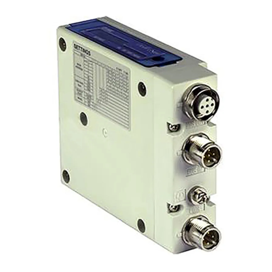
Summary of Product elements <EX260-SPR1/-SPR2/-SPR3/-SPR4> Element Description 1 Fieldbus interface connector PROFIBUS DP connection. (BUS OUT) (M12 5-pin socket, B-coded) 1 Fieldbus interface connector PROFIBUS DP connection. (BUS IN) (M12 5-pin plug, B-coded) 1 Power supply with load voltage for valves and operating voltage for SI unit. Power supply connector (M12 5-pin plug, A-coded) Ground terminal... - Page 11 <EX260-SPR5/-SPR6/-SPR7/-SPR8> Element Description 1 PROFIBUS DP connection. Fieldbus interface connector (D-sub 9-pin socket) 1 Power supply with load voltage for valves and operating voltage for SI unit. Power supply connector (M12 5-pin plug, A-coded) Functional earth. (M3 screw) Ground terminal Output signal interface for valve manifold.
-
Page 12: Installation And Wiring
Installation and Wiring ■Installation Connect valve manifold to the SI unit. •Dimensions for installation n: number of valve stations 120.7 136.7 152.7 168.7 184.7 200.7 216.7 232.7 248.7 264.7 280.7 296.7 312.7 328.7 344.7 (mm) The above table shows dimensions as an example for the SY5000 series valve manifold. Connectable valve manifolds are the same as for EX250 series SI unit. -
Page 13: Wiring
■Wiring Select the appropriate cables to mate with the connectors mounted on the SI unit. ○Fieldbus interface connector layout <EX260-SPR1/-SPR2/-SPR3/-SPR4> BUS OUT: M12 5-pin socket, B-coded Designation Description Unused RXD/TXD-N Receive / transmit data, negative Unused RXD/TXD-P Receive / transmit data, positive Unused BUS IN: M12 5-pin plug, B-coded Designation... - Page 14 <EX260-SPR5/-SPR6/-SPR7/-SPR8> BUS: D-sub 9-pin socket Designation Description Unused Unused RXD/TXD-P Receive / transmit data, positive Unused Data ground DGND (reference potential to VP) Power supply plus (P5V) Unused RXD/TXD-N Receive / transmit data, negative Unused Use the PROFIBUS DP connector with bus cable. (e.g.: 6ES7 972-0BA12-0XA0, manufactured by Siemens) ○PROFIBUS DP bus cable A shielded twisted pair cable for PROFIBUS DP should be used.
- Page 15 ○Power supply connector layout PWR: M12 5-pin plug, A-coded Designation Description SV24 V +24 V for solenoid valve SV0 V 0 V for solenoid valve SI24 V +24 V for SI unit operation SI0 V 0 V for SI unit operation Unused Power-supply line for solenoid valve and power-supply line for SI unit operation are isolated.
- Page 16 ○Ground terminal Connect the ground terminal to ground. Resistance to ground should be 100 ohms or less. <EX260-SPR1/-SPR2/-SPR3/-SPR4> <EX260-SPR5/-SPR6/-SPR7/-SPR8> -15- No.EX##-OMN0009-E...
-
Page 17: Led Indication And Settings
LED Indication and Settings ○LED indication Description System fault BUS fault Turns ON in green when SI unit operating voltage is supplied Turns ON in green when load voltage for the valve is supplied. PWR(V) Turns OFF when load voltage for the valve is not supplied or outside tolerance range. (19 V or less) <Indication of communication status>... - Page 18 ○PROFIBUS DP address setting and Fail safe setting (SETTINGS) Set the PROFIBUS DP node address and fail safe mode, i.e. reaction of outputs to the communication error, of the SI unit using the 8-element switch. Note 1. To set with switch, use a small blade screwdriver to flip the switches 2.
- Page 19 ○Terminator A bus termination is required at both ends of the PROFIBUS DP bus segment. <EX260-SPR1/-SPR2/-SPR3/-SPR4> The bus termination switch is built-in to EX260-SPR1/-SPR2/-SPR3/-SPR4. Switch it ON if the SI unit is at the end of the fieldbus segment. : Factory default setting is OFF. Note •Be sure to fit a seal cap on any unused connectors.
- Page 20 <EX260-SPR5/-SPR6/-SPR7/-SPR8> EX260-SPR5/-SPR6/-SPR7/-SPR8 do not have a built-in termination resistor. Termination is required on the outside of the SI unit. A termination switch built-in to the PROFIBUS DP D-sub connector may be used. -19- No.EX##-OMN0009-E...
- Page 21 ○Configuration In order to configure the SI unit in the PROFIBUS DP network, the appropriate device master file (GSD file) for the SI unit will be required. The current GSD file can be found on the SMC website (URL http://www.smcworld.com). GSD file Part number GSD file...
- Page 22 ○Output number assignment Output data : The output number refers to the solenoid position on the manifold and starts at zero. : Standard wiring on the manifold is for double-solenoid valves and output number starts A side and B side in that order as shown in the figure a.
- Page 23 ○Diagnostic information The EX260 SI unit can support 8 bytes of diagnostic information, 6 bytes standard diagnostic information and 2 bytes SI unit-related diagnostic information. Diagnostic information can be requested by the DP master from the SI unit, and such system fault states can be indicated by the SF LED.
- Page 24 Byte1: Station Status 2 Bit 7 Diag. Prm_Req Diag. Deactivated ”1” means that the SI unit setting ”1” means that the SI unit is is in the process of being de-activated changed by the DP master Reserved Diag. Stat_Diag Diag. Sync_Mode This bit is always “0”...
-
Page 25: Troubleshooting And Maintenance
Troubleshooting and Maintenance ○Troubleshooting chart When any malfunction is observed, it is recommended to perform the following troubleshooting. SI unit Refer to fault SI unit PWR LED is OFF malfunction No.1 SI unit Refer to fault PWR (V) LED is No.2 SI unit SI unit... - Page 26 Troubleshooting table Fault No.1 Fault Probable cause Recommended error handling Recommended action Re-tighten the power cable. (Replace the cable if it is Defective power cable Check the condition of the power cable broken) wiring for SI unit SI unit wiring to the SI unit. operation PWR LED is Correct the power cable...
- Page 27 Fault No.5 Fault Probable cause Recommended error handling Recommended action SI unit Check if the configured setup to the SI unit BF LED is Invalid configuration Configure the SI unit by DP by DP master match the actual setup of the flashing data master using valid GSD file.
- Page 28 ○Maintenance Replacement of the SI unit •Remove the M3 hexagon screws from the SI unit and release the SI unit from the valve manifold. •Replace the SI unit. •Tighten the screws with the specified tightening torque. (0.6 Nm) Precautions for maintenance (1) Be sure to switch off the power.
-
Page 29: Specifications
Specifications ■Specifications General specifications Item Specifications Ambient temperature -10 to +50 Ambient humidity 35 to 85%RH (No condensate) Ambient temperature for storage -20 to +60 Withstand voltage 500 VAC applied for 1 minute Insulation resistance 500 VDC, 10 MΩ or more Operating atmosphere No corrosive gas ... - Page 30 Network communication specifications Item Specifications Protocol PROFIBUS DP (EN50170, EN50254) 9.6, 19.2, 45.45, 93.75, 187.5, 500, 1500, Transmission speed 3000, 6000, 12000 (kbps) Device type DP slave EX260-SPR1/-SPR2/-SPR5/-SPR6 32 outputs Number of outputs EX260-SPR3/-SPR4/-SPR7/-SPR8 16 outputs EX260-SPR1/-SPR2 Smc_1430.gsd EX260-SPR3/-SPR4 Smc_1431.gsd Configuration file EX260-SPR5/-SPR6 Smc_1432.gsd...
-
Page 31: Dimensions
■Dimensions •EX260-SPR1/-SPR2/-SPR3/-SPR4 •EX260-SPR5/-SPR6/-SPR7/-SPR8 •If a fieldwireable connector is used for the power supply connection, and the SI unit is installed directly to a valve manifold, the connector should be 16 mm or less. If the connector is a larger diameter it will interfere with the clamping face. Recommended cables are specified in the accessories section, on page 31. -
Page 32: Accessories
Accessories ○Connector cable •Compatible connectors for EX260-SPR1/-SPR2/-SPR3/-SPR4 Compatible connector SI unit connector Description Part number Specifications Manufacturer Communication cable for Connector: M12 straight Fieldbus PCA-1557691 PROFIBUS DP Cable: 5 m interface connector Fieldwireable connector PCA-1557701 Connector: M12 straight (BUS OUT) for PROFIBUS DP Communication cable for Connector: M12 straight... - Page 33 Revision history A: Revise some wording B: Revision C: Revision D: Limited warranty and Disclaimer are added. E: Contents revised in several places. Note: Specifications are subject to change without prior notice and any obligation on the part of the manufacturer. ©...
Need help?
Do you have a question about the EX260 Series and is the answer not in the manual?
Questions and answers