
Subscribe to Our Youtube Channel
Related Manuals for SMC Networks EX12 SMJ1 Series


Summary of Contents for SMC Networks EX12 SMJ1 Series
- Page 1 No.EX※※-OMB0014-H PRODUCT NAME SI unit for CC-Link MODEL / Series / Product Number EX12#-SMJ1 Series...
-
Page 2: Table Of Contents
Table of Contents Safety Instructions Model Indication and How to Order Summary of Product parts Definition and terminology Mounting and Installation Communication wiring Power supply wiring Settings Maintenance Troubleshooting Specifications Dimensions No.EX※※-OMB0014-H... -
Page 3: Safety Instructions
Safety Instructions These safety instructions are intended to prevent hazardous situations and/or equipment damage. These instructions indicate the level of potential hazard with the labels of "Caution", "Warning" or "Danger". They are all important notes for safety and must be followed in addition to International Standards (ISO/IEC) , and other safety regulations. - Page 4 Safety Instructions Caution 1.The product is provided for use in manufacturing industries. The product herein described is basically provided for peaceful use in manufacturing industries. If considering using the product in other industries, consult SMC beforehand and exchange specifications or a contract if necessary. If anything is unclear, contact your nearest sales branch.
- Page 5 Operator ♦This operation manual is intended for those who have knowledge of machinery using pneumatic equipment, and have sufficient knowledge of assembly, operation and maintenance of such equipment. Only those persons are allowed to perform assembly, operation and maintenance. ♦Read and understand this operation manual carefully before assembling, operating or providing maintenance to the product.
- Page 6 Caution ■After maintenance is complete, perform appropriate functional inspections. Stop operation if the equipment does not function properly. Safety cannot be assured in the case of unexpected malfunction. ■Provide grounding to assure the noise resistance of the Serial System. Individual grounding should be provided close to the product with a short cable. ■NOTE ○Follow the instructions given below when designing, selecting and handling the product.
- Page 7 ●Product handling ∗Installation •Do not drop, hit or apply excessive shock to the fieldbus system. Otherwise damage to the product can result, causing malfunction. •Tighten to the specified tightening torque. If the tightening torque is exceeded the mounting screws may be broken. •Never mount a product in a location that will be used as a foothold.
- Page 8 •Mount the product in a place that is not exposed to excessive vibration or impact. Otherwise failure or malfunction can result. •Do not use the product in an environment that is exposed to temperature cycle. Heat cycles other than ordinary changes in temperature can adversely affect the inside of the product. •Do not expose the product to direct sunlight.
-
Page 9: Model Indication And How To Order
Model Indication and How to Order EX120-SMJ 1 Output type 16 outputs, NPN (positive common) / sink Fieldbus CC-Link Valve interface EX120 Direct mounting - Plug in EX121 DIN rail mounting - Flat ribbon cable EX122 DIN rail mounting - Plug in EX124U Direct mounting - Plug in (IP65) U side EX124D... -
Page 10: Summary Of Product Parts
Summary of Product parts •EX120-SMJ1 •EX121-SMJ1 •EX122-SMJ1 No.EX※※-OMB0014-H... - Page 11 •EX124D/U-SMJ1 •EX126D-SMJ1 -10- No.EX※※-OMB0014-H...
-
Page 12: Definition And Terminology
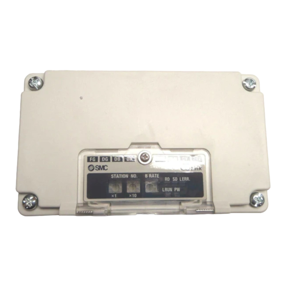
○Terminal block (with switch cover open) Element Description Output connector To connect to the valve manifold LED display to indicate the status of the SI unit. LED and Switch cover Switches for setting the station number and transmission speed. Communication terminals (DA, DB, DG) To connect the CC-Link line with a CC-Link-dedicated cable. -
Page 13: Mounting And Installation
Mounting and Installation ■Communication wiring The connection between a CC-Link-dedicated cable and an SI unit communication terminal for CC-Link is shown below. (1) Be sure to connect each signal line to its dedicated terminal. (Refer to Fig. 1) Tighten the screws securely with a torque of 0.5 to 0.6 N•m. The terminal screw is an M3 cross head screw. - Page 14 (4) The CC-Link-dedicated cable’s shield wire (SLD) should be connected to the “FG” terminal of the SI unit. For the EX12#-SMJ1, the "SLD terminal" and "FG terminal" are common. Therefore, connect 3 wires to the "FG Terminal" as shown in Fig. 4. Fig.
-
Page 15: Power Supply Wiring
■Power supply wiring Connect the power supply wiring to the solenoid valve power supply terminals and to the SI unit control power supply terminals. Although the power supply consists of two separate systems, it is possible to use either a single power supply or separate power supplies. -
Page 16: Settings
Settings ○Display setting Display Meaning LED is ON when the communication power is ON Indicates whether the SI unit is communicating with the master station correctly. L RUN LED is ON when the SI unit is receiving normal data from the master station. LED is OFF during time-out. - Page 17 ○Switch setting The setting for the station number and communication speed can be carried out using the rotary switches under the LED and switch cover. The settings must be carried out with the power supply for the SI unit turned off. •Station number setting Setting Setting range...
- Page 18 ○Output and error information (1) I/O mapping table for master station Buffer Memory. EX12#-SMJ1 is a remote I/O station (1 station occupied, 32 inputs/32 outputs). An example of when the SI unit station number is set to 01 is shown below. Master station buffer area I/O memory map of EX12#-SMJ1 e.g.: “QJ61BT11N”...
- Page 19 (2) Output number assignment The output number refers to the D side solenoid position on the manifold and starts at zero. ∗: Standard wiring of the manifold is for double-solenoid valves and the output number starts at the A side and then B side in that order as shown in the figure a.
-
Page 20: Maintenance
Maintenance •Mounting and wiring Item to inspect Criteria Countermeasure Are SI unit terminals Tighten the connector. (for communication and power supply) No looseness (Refer to “Mounting/ Installation”) securely connected? Are the terminating resistors securely Connect suitable terminating resistors to connected to both ends of the network Terminating resistors must be cables. - Page 21 ○Fuse replacement (Only EX126D-SMJ1) If an over current occurs in the power supply for communication or the power supply for solenoid valves, due to a short circuit etc, the fuse will disconnect the supply. In this case, remove the cause of the over current and replace the fuse. The fuse replacement should only be performed with the SI unit disconnected from the valve manifold.
-
Page 22: Troubleshooting
Troubleshooting ○Troubleshooting Applicable model: EX12#-SMJ1 If an operation failure of the product occurs, please confirm the cause of the failure from the following table. If a cause applicable to the failure cannot be identified and normal operation can be recovered by replacement with a new product, this indicates that the product itself was faulty. - Page 23 ○Faults and countermeasures Trouble Problem Possible cause Investigation method Countermeasure Check the power supply for communication cable for breaks, and Power supply for check that the terminals are not Connect the power supply communication loose. cable correctly. wiring failure. Avoid repetitive bending and stress on the cables, which may cause SI unit PW damage...
- Page 24 Trouble Problem Possible cause Investigation method Countermeasure Communication Check that the SI unit communication speed setting speed setting and the setting in the SI unit L RUN error master station are the same LED is ON Correct the setting. Station number Check that the station number setting error or SD LED is OFF...
- Page 25 <Precautions for replacement of SI unit> 1. Be sure to turn the power OFF before replacing the SI unit. Otherwise injury or SI unit malfunction can result. 2. Check the wiring before supplying power. Otherwise damage to the SI unit can result in some wiring conditions, causing breakdown or malfunction. 3.
- Page 26 3. This releases the lock. Pull the SI unit slowly and remove from the manifold. •Precautions when opening the cover When opening the cover, hold both sides of the cover. -25- No.EX※※-OMB0014-H...
- Page 27 •Mounting 1. Align the raised part on the manifold side at the bottom of the SI unit with the groove of the manifold, and press it in evenly. 2. Confirm that the SI unit and manifold are securely locked together, and slide the SI unit downwards. -26- No.EX※※-OMB0014-H...
- Page 28 ○How to replace the EX121/122 Series SI unit •Removal 1. Loosen the mounting bracket screw. 2. Remove the SI unit by unhooking claw 2 then claw 1. •Mounting 1. Hook claw 1 to the upper side of the DIN rail and claw 2 to the lower side. 2.
- Page 29 ○How to replace the EX124/EX126 Series SI unit •Removal 1. Remove the cover from the SI unit, by removing the screws (4 x M4) which hold the cover. 2. Disconnect the wiring from the SI unit, and remove the SI unit from the manifold. Disconnect the wiring to the SI unit.
- Page 30 <EX124 series> 3. Remove the manifold wiring from the SI unit. Pull out the cable with connector (manifold wiring) from the manifold while holding the board of the SI unit. Pulling direction Board Cable with connector •Mounting 1. Connect the manifold wiring to the SI unit. (Follow the procedure of step 3 in reverse.) •Ensure the cable (manifold wiring) does not get caught between the SI unit and the manifold.
- Page 31 <EX126 series> 3. Remove the manifold wiring from the SI unit. •Mounting 1. Mount the SI unit to the manifold, then wiring the communication terminal and power terminal. 2. Mount the cover to the SI unit after setting the switches. Tighten the screws diagonally so that the cover unit is securely fitted.
-
Page 32: Specifications
Specifications Model No. EX12#-SMJ1 Applicable system CC-Link Ver.1.10 Occupied station 1 station Station number setting 1 to 64 (Set with a rotary switch) range Communication Station type Remote I/O specification Communication speed 156 k/625 k/2.5 M/5 M/10 Mbps Cable length between 20 cm or more stations Max. -
Page 33: Dimensions
■Dimensions •EX120-SMJ1 •EX121-SMJ1 -32- No.EX※※-OMB0014-H... - Page 34 •EX122-SMJ1 •EX124D/U-SMJ1 -33- No.EX※※-OMB0014-H...
- Page 35 •EX126D-SMJ1 -34- No.EX※※-OMB0014-H...
- Page 36 Revision history C: Complete revision D: Terminal screw change Switch cover change (EX124U/D, EX126D) E: Modified errors in text. (Page 14) F: Limited warranty and Disclaimer are added. G: Contents revised in several places. H: Contents are added [September 2021] 4-14-1, Sotokanda, Chiyoda-ku, Tokyo 101-0021 JAPAN Tel: + 81 3 5207 8249 Fax: +81 3 5298 5362 https://www.smcworld.com...
Need help?
Do you have a question about the EX12 SMJ1 Series and is the answer not in the manual?
Questions and answers