ABB Relion 670 Series Applications Manual
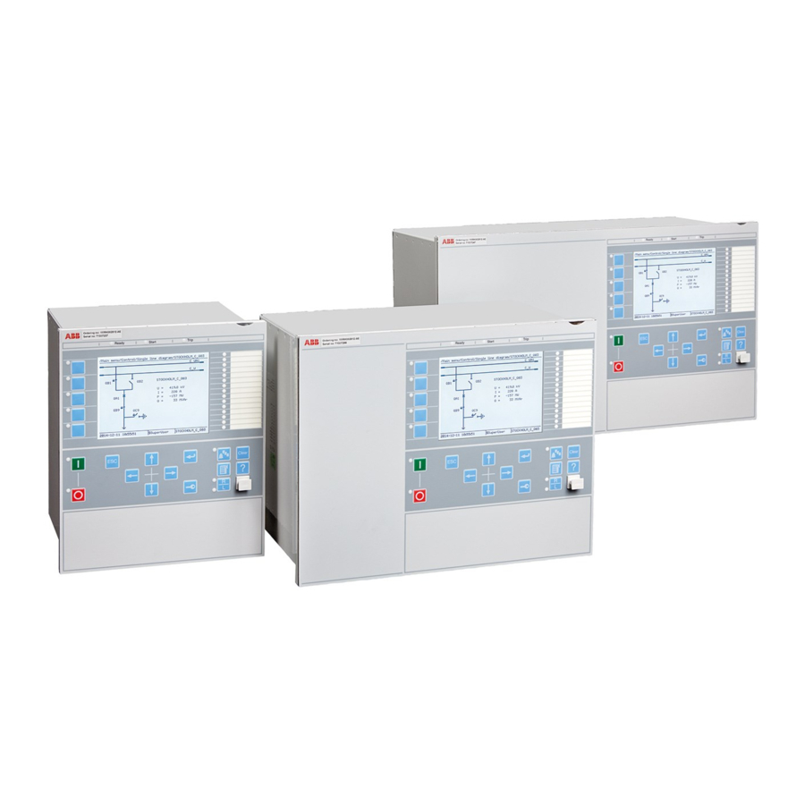
Phasor measurement unit
Hide thumbs
Also See for Relion 670 Series:
- Technical manual (1432 pages) ,
- Technical reference manual (1232 pages) ,
- Applications manual (944 pages)

Subscribe to Our Youtube Channel
Related Manuals for ABB Relion 670 Series


Summary of Contents for ABB Relion 670 Series
- Page 1 ® Relion 670 SERIES Phasor measurement unit RES670 Version 2.2 ANSI Application manual...
- Page 3 Document ID: 1MRK 511 407-UUS Issued: September 2020 Revision: J Product version: 2.2 © Copyright 2017 Hitachi Power Grids. All rights reserved...
- Page 4 (https://www.openssl.org/) This product includes cryptographic software written/developed by: Eric Young (eay@cryptsoft.com) and Tim Hudson (tjh@cryptsoft.com). Trademarks ABB and Relion are registered trademarks of the ABB Group. All other brand or product names mentioned in this document may be trademarks or registered trademarks of their respective holders.
- Page 5 Grids be responsible or liable for any loss or damage resulting from the use of this manual or the application of the equipment. ABB is a registered trademark of ABB Asea Brown Boveri Ltd. Manufactured by/for a Hitachi Power Grids company.
- Page 6 Conformity This product complies with the directive of the Council of the European Communities on the approximation of the laws of the Member States relating to electromagnetic compatibility (EMC Directive 2004/108/EC) and concerning electrical equipment for use within specified voltage limits (Low-voltage directive 2006/95/EC).
-
Page 7: Table Of Contents
1MRK 511 407-UUS Rev. J Table of contents Table of contents Section 1 Introduction......................15 This manual............................15 Intended audience..........................15 Product documentation........................16 1.3.1 Product documentation set......................16 1.3.2 Document revision history......................17 1.3.3 Related documents.........................18 Document symbols and conventions.................... 18 1.4.1 Symbols.............................18 1.4.2 Document conventions........................ - Page 8 Table of contents 1MRK 511 407-UUS Rev. J 4.2.2.6 Example how to connect delta connected three-phase CT set to the IED....60 4.2.2.7 Example how to connect single-phase CT to the IED............62 4.2.3 Relationships between setting parameter Base Current, CT rated primary current and minimum pickup of a protection IED..................63 4.2.4 Setting of voltage channels......................64...
- Page 9 1MRK 511 407-UUS Rev. J Table of contents 7.1.4 Setting guidelines.........................105 Out-of-step protection OOSPPAM (78)..................111 7.2.1 Identification..........................111 7.2.2 Application............................111 7.2.3 Setting guidelines......................... 114 Section 8 Current protection...................117 Directional phase overcurrent protection, four steps OC4PTOC(51_67)......117 8.1.1 Identification..........................117 8.1.2 Application............................
- Page 10 Table of contents 1MRK 511 407-UUS Rev. J 8.6.3 Setting guidelines......................... 152 Directional overpower protection GOPPDOP (32)..............156 8.7.1 Identification..........................156 8.7.2 Application............................. 156 8.7.3 Setting guidelines.........................158 Section 9 Voltage protection..................163 Two step undervoltage protection UV2PTUV (27)..............163 9.1.1 Identification..........................163 9.1.2 Application.............................
- Page 11 1MRK 511 407-UUS Rev. J Table of contents 10.4.3 Setting guidelines......................... 177 Section 11 Multipurpose protection.................179 11.1 General current and voltage protection CVGAPC..............179 11.1.1 Identification..........................179 11.1.2 Application............................. 179 11.1.2.1 Current and voltage selection for CVGAPC function............180 11.1.2.2 Base quantities for CVGAPC function................. 182 11.1.2.3 Application possibilities......................182 11.1.2.4...
- Page 12 Table of contents 1MRK 511 407-UUS Rev. J 13.3.1 Function revision history......................204 13.3.2 Identification..........................204 13.3.3 Application.............................204 13.3.4 Setting guidelines........................206 13.4 Current based delta supervision DELISPVC(7I)................ 206 13.4.1 Identification..........................206 13.4.2 Application.............................206 13.4.3 Setting guidelines.........................207 13.5 Delta supervision of real input DELSPVC...................208 13.5.1 Identification..........................208 13.5.2...
- Page 13 1MRK 511 407-UUS Rev. J Table of contents 15.1.3 Application............................217 15.1.3.1 Three-pole tripping......................... 218 15.1.3.2 Single- and/or three-pole tripping..................218 15.1.3.3 Single-, two- or three-pole tripping ..................220 15.1.3.4 Lock-out............................ 220 15.1.3.5 Example of directional data....................221 15.1.3.6 Blocking of the function block....................223 15.1.4 Setting guidelines.........................223 15.2...
- Page 14 Table of contents 1MRK 511 407-UUS Rev. J 15.12.3 Setting guidelines.........................233 15.13 Comparator for integer inputs - INTCOMP................234 15.13.1 Identification..........................234 15.13.2 Application............................. 234 15.13.3 Setting guidelines.........................234 15.13.4 Setting example..........................234 15.14 Comparator for real inputs - REALCOMP................... 235 15.14.1 Function revision history......................235 15.14.2 Identification..........................
- Page 15 1MRK 511 407-UUS Rev. J Table of contents 16.6.4 Setting guidelines.........................259 16.6.4.1 Recording times........................261 16.6.4.2 Binary input signals........................ 262 16.6.4.3 Analog input signals....................... 262 16.6.4.4 Sub-function parameters...................... 263 16.6.4.5 Consideration.......................... 263 16.7 Logical signal status report BINSTATREP..................264 16.7.1 Identification..........................264 16.7.2 Application.............................264 16.7.3...
- Page 16 Table of contents 1MRK 511 407-UUS Rev. J 18.2 Redundant communication......................276 18.2.1 Identification..........................276 18.2.2 Application............................. 276 18.2.3 Setting guidelines.........................278 18.3 Merging unit.............................278 18.3.1 Application............................. 278 18.3.2 Setting guidelines.........................279 18.4 Routes............................... 279 18.4.1 Application............................. 279 18.4.2 Setting guidelines.........................279 Section 19 Station communication..................
- Page 17 1MRK 511 407-UUS Rev. J Table of contents 19.7 DNP3 Communication protocol....................306 19.7.1 Application.............................306 Section 20 Remote communication................. 307 20.1 Binary signal transfer........................307 20.1.1 Identification..........................307 20.1.2 Application............................. 307 20.1.2.1 Communication hardware solutions.................. 308 20.1.3 Setting guidelines........................309 Section 21 Security......................
- Page 18 Table of contents 1MRK 511 407-UUS Rev. J 22.7.3 Setting guidelines.........................323 22.8 Signal matrix for binary inputs SMBI...................323 22.8.1 Application............................. 323 22.8.2 Setting guidelines.........................323 22.9 Signal matrix for binary outputs SMBO ..................324 22.9.1 Application............................. 324 22.9.2 Setting guidelines.........................324 22.10 Signal matrix for mA inputs SMMI....................324 22.10.1 Application.............................
- Page 19 1MRK 511 407-UUS Rev. J Table of contents 23.5 Sample specification of communication requirements for the protection and control terminals in digital telecommunication networks.............345 23.6 IEC/UCA 61850-9-2LE Merging unit requirements ..............346 Section 24 Glossary ......................347 Phasor measurement unit RES670 Application manual ©...
-
Page 21: Introduction
1MRK 511 407-UUS Rev. J Section 1 Introduction Section 1 Introduction This manual GUID-AB423A30-13C2-46AF-B7FE-A73BB425EB5F v20 The application manual contains application descriptions and setting guidelines sorted per function. The manual can be used to find out when and for what purpose a typical protection function can be used. -
Page 22: Product Documentation
Section 1 1MRK 511 407-UUS Rev. J Introduction Product documentation 1.3.1 Product documentation set GUID-3AA69EA6-F1D8-47C6-A8E6-562F29C67172 v16 Engineering manual Installation manual Commissioning manual Operation manual Application manual Technical manual Communication protocol manual Cyber security deployment guideline IEC07000220-4-en.vsd IEC07000220 V4 EN-US Figure 1: The intended use of manuals throughout the product lifecycle The engineering manual contains instructions on how to engineer the IEDs using the various tools available within the PCM600 software. -
Page 23: Document Revision History
1MRK 511 407-UUS Rev. J Section 1 Introduction The operation manual contains instructions on how to operate the IED once it has been commissioned. The manual provides instructions for the monitoring, controlling and setting of the IED. The manual also describes how to identify disturbances and how to view calculated and measured power grid data to determine the cause of a fault. -
Page 24: Related Documents
Section 1 1MRK 511 407-UUS Rev. J Introduction 1.3.3 Related documents GUID-94E8A5CA-BE1B-45AF-81E7-5A41D34EE112 v8 Documents related to RES670 Document numbers Application manual 1MRK 511 407-UUS Commissioning manual 1MRK 511 409-UUS Product guide 1MRK 511 410-BEN Technical manual 1MRK 511 408-UUS Type test certificate 1MRK 511 410-TUS 670 series manuals Document numbers... -
Page 25: Document Conventions
1MRK 511 407-UUS Rev. J Section 1 Introduction The information icon alerts the reader of important facts and conditions. The tip icon indicates advice on, for example, how to design your project or how to use a certain function. Although warning hazards are related to personal injury, it is necessary to understand that under certain operational conditions, operation of damaged equipment may result in degraded process performance leading to personal injury or death. - Page 26 Section 1 1MRK 511 407-UUS Rev. J Introduction Function block name Edition 1 logical nodes Edition 2 logical nodes ALTRK ALTRK BCZPDIF BCZPDIF BCZPDIF BCZSPDIF BCZSPDIF BCZSPDIF BCZTPDIF BCZTPDIF BCZTPDIF BDCGAPC SWSGGIO BBCSWI BDCGAPC BDZSGAPC BBS6LLN0 LLN0 BDZSGAPC BDZSGAPC BFPTRC_F01 BFPTRC BFPTRC BFPTRC_F02...
- Page 27 1MRK 511 407-UUS Rev. J Section 1 Introduction Function block name Edition 1 logical nodes Edition 2 logical nodes BTIGAPC B16IFCVI BTIGAPC BUSPTRC_B1 BUSPTRC BUSPTRC BBSPLLN0 BUSPTRC_B2 BUSPTRC BUSPTRC BUSPTRC_B3 BUSPTRC BUSPTRC BUSPTRC_B4 BUSPTRC BUSPTRC BUSPTRC_B5 BUSPTRC BUSPTRC BUSPTRC_B6 BUSPTRC BUSPTRC BUSPTRC_B7 BUSPTRC...
- Page 28 Section 1 1MRK 511 407-UUS Rev. J Introduction Function block name Edition 1 logical nodes Edition 2 logical nodes BZNPDIF_Z3 BZNPDIF BZNPDIF BZNPDIF_Z4 BZNPDIF BZNPDIF BZNPDIF_Z5 BZNPDIF BZNPDIF BZNPDIF_Z6 BZNPDIF BZNPDIF BZNSPDIF_A BZNSPDIF BZASGAPC BZASPDIF BZNSGAPC BZNSPDIF BZNSPDIF_B BZNSPDIF BZBSGAPC BZBSPDIF BZNSGAPC BZNSPDIF...
- Page 29 1MRK 511 407-UUS Rev. J Section 1 Introduction Function block name Edition 1 logical nodes Edition 2 logical nodes DPGAPC DPGGIO DPGAPC DRPRDRE DRPRDRE DRPRDRE ECPSCH ECPSCH ECPSCH ECRWPSCH ECRWPSCH ECRWPSCH EF4PTOC EF4LLN0 EF4PTRC EF4PTRC EF4RDIR EF4RDIR GEN4PHAR GEN4PHAR PH1PTOC PH1PTOC EFPIOC EFPIOC...
- Page 30 Section 1 1MRK 511 407-UUS Rev. J Introduction Function block name Edition 1 logical nodes Edition 2 logical nodes LAPPGAPC LAPPLLN0 LAPPPDUP LAPPPDUP LAPPPUPF LAPPPUPF LCCRPTRC LCCRPTRC LCCRPTRC LCNSPTOC LCNSPTOC LCNSPTOC LCNSPTOV LCNSPTOV LCNSPTOV LCP3PTOC LCP3PTOC LCP3PTOC LCP3PTUC LCP3PTUC LCP3PTUC LCPTTR LCPTTR LCPTTR...
- Page 31 1MRK 511 407-UUS Rev. J Section 1 Introduction Function block name Edition 1 logical nodes Edition 2 logical nodes OEXPVPH OEXPVPH OEXPVPH OOSPPAM OOSPPAM OOSPPAM OOSPTRC OV2PTOV GEN2LLN0 OV2PTOV OV2PTOV PH1PTRC PH1PTRC PAPGAPC PAPGAPC PAPGAPC PCFCNT PCGGIO PCFCNT PH4SPTOC GEN4PHAR GEN4PHAR OCNDLLN0 PH1BPTOC...
- Page 32 Section 1 1MRK 511 407-UUS Rev. J Introduction Function block name Edition 1 logical nodes Edition 2 logical nodes SPC8GAPC SPC8GGIO SPC8GAPC SPGAPC SPGGIO SPGAPC SSCBR SSCBR SSCBR SSIMG SSIMG SSIMG SSIML SSIML SSIML PTRSTHR PTRSTHR PTRSTHR STBPTOC STBPTOC BBPMSS STBPTOC STEFPHIZ STEFPHIZ...
- Page 33 1MRK 511 407-UUS Rev. J Section 1 Introduction Function block name Edition 1 logical nodes Edition 2 logical nodes VRPVOC VRLLN0 PH1PTRC PH1PTRC PH1PTUV PH1PTUV VRPVOC VRPVOC VSGAPC VSGGIO VSGAPC WRNCALH WRNCALH WRNCALH ZC1PPSCH ZPCPSCH ZPCPSCH ZC1WPSCH ZPCWPSCH ZPCWPSCH ZCLCPSCH ZCLCPLAL ZCLCPSCH ZCPSCH...
-
Page 35: Application
1MRK 511 407-UUS Rev. J Section 2 Application Section 2 Application General IED application GUID-CF75762E-73C1-40AF-8D6F-6EC3D8395982 v4 RES670 is a Phasor Measurement Unit (PMU) that provides power system AC voltages and currents as phasors for all voltage levels in power system networks. Phasors are provided as real and imaginary or as magnitude and phase angle. - Page 36 Section 2 1MRK 511 407-UUS Rev. J Application Visualization (Applications) Interface to SCADA / EMS Phasor Data Concentrator Data Storage and Event Driven Archiving Gateway to other Utilities TCP/IP communication network PMU protocol IEEE C37.118 Router Router Router Router PTP or PTP or PTP or PTP or...
-
Page 37: Wide Area Measurement Functions
1MRK 511 407-UUS Rev. J Section 2 Application GUID-F5776DD1-BD04-4872-BB89-A0412B4B5CC3 v1 The following tables list all the functions available in the IED. Those functions that are not exposed to the user or do not need to be configured are not described in this manual. - Page 38 Section 2 1MRK 511 407-UUS Rev. J Application IEC 61850 or ANSI Function description function name RES670 (Customized) OC4PTOC Directional phase overcurrent protection, four steps 51_67 EF4PTOC Directional residual overcurrent protection, four steps NS4PTOC 46I2 Directional negative phase sequence overcurrent protection, four steps SDEPSDE Sensitive directional residual overcurrent and power...
-
Page 39: Control And Monitoring Functions
1MRK 511 407-UUS Rev. J Section 2 Application Control and monitoring functions GUID-E3777F16-0B76-4157-A3BF-0B6B978863DE v20 IEC 61850 or ANSI Function description Phasor function name measurement unit RES670 (Customized) Control QCBAY Bay control LOCREM Handling of LR-switch positions LOCREMCTRL LHMI control of PSTO SXCBR Circuit breaker SLGAPC... - Page 40 Section 2 1MRK 511 407-UUS Rev. J Application IEC 61850 or ANSI Function description Phasor function name measurement unit RES670 (Customized) FUFSPVC Fuse failure supervision DELVSPVC 7V_78 Voltage delta supervision, 2 phase DELISPVC Current delta supervision, 2 phase DELSPVC Real delta supervision, real Logic SMPPTRC...
- Page 41 1MRK 511 407-UUS Rev. J Section 2 Application IEC 61850 or ANSI Function description Phasor function name measurement unit RES670 (Customized) IB16 Integer to Boolean 16 conversion ITBGAPC Integer to Boolean 16 conversion with Logic Node representation TEIGAPC Elapsed time integrator with limit transgression and overflow supervision INTCOMP...
- Page 42 Section 2 1MRK 511 407-UUS Rev. J Application IEC 61850 or ANSI Function description Phasor function name measurement unit RES670 (Customized) BINSTATREP Logical signal status report RANGE_XP Measured value expander block SSIMG Insulation supervision for gas medium SSIML Insulation supervision for liquid medium SSCBR Circuit breaker condition...
- Page 43 1MRK 511 407-UUS Rev. J Section 2 Application Table 2: Total number of instances for basic configurable logic blocks Basic configurable logic block Total number of instances GATE PULSETIMER RSMEMORY SRMEMORY TIMERSET Table 3: Total number of instances for configurable logic blocks Q/T Configurable logic blocks Q/T Total number of instances ANDQT...
-
Page 44: Communication
Section 2 1MRK 511 407-UUS Rev. J Application Extended configurable logic block Total number of instances TIMERSET VSGAPC Communication GUID-5F144B53-B9A7-4173-80CF-CD4C84579CB5 v18 IEC 61850 or function ANSI Function description Phasor name measurement unit RES670 (Customized) Station communication LON communication protocol HORZCOMM Network variables via LON PROTOCOL Operation selection between SPA and IEC60870-5-103 for... - Page 45 1MRK 511 407-UUS Rev. J Section 2 Application IEC 61850 or function ANSI Function description Phasor name measurement unit RES670 (Customized) PCMACCS IED configuration protocol SECALARM Component for mapping security events on protocols such as DNP3 and IEC103 FSTACCSNA Field service tool access via SPA protocol over Ethernet communication FSTACCS Field service tool access...
-
Page 46: Basic Ied Functions
Section 2 1MRK 511 407-UUS Rev. J Application IEC 61850 or function ANSI Function description Phasor name measurement unit RES670 (Customized) LDCMTRN_2M_305 Transmission of analog data from LDCM, 2Mbit LDCMTRN_2M_306 LDCMTRN_2M_312 LDCMTRN_2M_313 LDCMTRN_2M_322 LDCMTRN_2M_323 LDCMRecBinStat1 Receive binary status from remote LDCM LDCMRecBinStat3 LDCMRecBinStat2 Receive binary status from LDCM... - Page 47 1MRK 511 407-UUS Rev. J Section 2 Application IEC 61850 or function Description name LONGEN LON communication RUNTIME IED Runtime component SMBI Signal matrix for binary inputs SMBO Signal matrix for binary outputs SMMI Signal matrix for mA inputs SMAI1 - SMAI12 Signal matrix for analog inputs 3PHSUM Summation block 3 phase...
-
Page 49: Configuration
PCM600 engineering platform. The IED can be adapted to special applications and special logic can be developed. On request, ABB is available to support the re-configuration work, either directly or to do the design checking. Optional functions and optional IO ordered, will not be configured at delivery. It means that the user shall configure and add them to the standard configuration. - Page 50 Section 3 1MRK 511 407-UUS Rev. J Configuration frequency data, is reporting 16 synchrophasors over IEEE C37.118/1344; that is four 3-phase synchrophasors and 12 single phase synchrophasors in each data stream corresponding to the AC voltage and current measurements. In addition, each data stream includes 8 analog and 8 binary reporting channels over IEEE C37.118/1344 in the standard configuration.
-
Page 51: Description Of Configuration B20
1MRK 511 407-UUS Rev. J Section 3 Configuration RES670 A20 – Phasor Measurement Unit, 3 bays, single busbar, 12AI (9I+3U) WA1_VT df/dt SA PFRC f> SA PTOF f< SA PTUF 2(3U<) UV2 PTUV 2(3U>) OV2 PTOV V MMXU Usqi DFR/SER DR V MSQI DRP RDRE IEEE Std 1344... - Page 52 Section 3 1MRK 511 407-UUS Rev. J Configuration can be extended to maximum 24 channels per PMU instance (on each data stream) on request. This can be done when ordering the RES670 B20 configuration. In the standard B20 configuration the analog reporting channels are used for reporting P and Q measurements from each bay over IEEE C37.118/1344.
- Page 53 1MRK 511 407-UUS Rev. J Section 3 Configuration RES670 B20 – Phasor Measurement Unit, 6 bays, double busbar, 24AI (9I+3U, 9I+3U) WA1_VT WA2_VT df/dt df/dt SA PFRC SA PFRC f> f> SA PTOF SA PTOF f< f< SA PTUF SA PTUF 2(3U<) 2(3U<) UV2 PTUV...
-
Page 55: Analog Inputs
1MRK 511 407-UUS Rev. J Section 4 Analog inputs Section 4 Analog inputs Introduction SEMOD55003-5 v11 Analog input channels must be configured and set properly in order to get correct measurement results and correct protection operations. For power measuring, all directional and differential functions, the directions of the input currents must be defined in order to reflect the way the current transformers are installed/connected in the field ( primary and secondary connections ). -
Page 56: Example
Section 4 1MRK 511 407-UUS Rev. J Analog inputs 4.2.1.1 Example SEMOD55055-11 v6 Usually the A phase-to-ground voltage connected to the first VT channel number of the transformer input module (TRM) is selected as the phase reference. The first VT channel number depends on the type of transformer input module. -
Page 57: Example 2
1MRK 511 407-UUS Rev. J Section 4 Analog inputs Line Transformer Line Reverse Forward Definition of direction for directional functions Transformer protection Line protection Setting of current input: Setting of current input: Setting of current input: Set parameter Set parameter Set parameter CT_WyePoint with CT_WyePoint with... - Page 58 Section 4 1MRK 511 407-UUS Rev. J Analog inputs Transformer Line Forward Reverse Definition of direction for directional Transformer and line functions Line protection Setting of current input: Setting of current input: Set parameter Set parameter CT_WyePoint with CT_WyePoint with Transformer as Transformer as reference object.
- Page 59 1MRK 511 407-UUS Rev. J Section 4 Analog inputs Transformer Line Reverse Forward Definition of direction for directional Transformer and line functions Line protection Setting of current input for line functions: Set parameter CT_WyePoint with Line as reference object. Setting of current input Setting of current input Correct setting is for transformer functions:...
- Page 60 Section 4 1MRK 511 407-UUS Rev. J Analog inputs Busbar Busbar Protection en06000196_ansi.vsd ANSI06000196 V1 EN-US Figure 10: Example how to set CT_WyePoint parameters in the IED CT_WyePoint parameters in two ways. For busbar protection, it is possible to set the The first solution will be to use busbar as a reference object.
-
Page 61: Examples On How To Connect, Configure And Set Ct Inputs For Most Commonly Used Ct Connections
1MRK 511 407-UUS Rev. J Section 4 Analog inputs CTprim = 1000 (value in A) • CTsec = 5 (value in A). • 4.2.2.4 Examples on how to connect, configure and set CT inputs for most commonly used CT connections SEMOD55055-296 v7 Figure defines the marking of current transformer terminals commonly used around the world:... -
Page 62: Example On How To Connect A Wye Connected Three-Phase Ct Set To The Ied
Section 4 1MRK 511 407-UUS Rev. J Analog inputs It is recommended to: • use 1A rated CT input into the IED in order to connect CTs with 1A and 2A secondary rating • use 5A rated CT input into the IED in order to connect CTs with 5A and 10A secondary rating 4.2.2.5 Example on how to connect a wye connected three-phase CT set to the IED... - Page 63 1MRK 511 407-UUS Rev. J Section 4 Analog inputs Where: The drawing shows how to connect three individual phase currents from a wye connected three-phase CT set to the three CT inputs of the IED. The current inputs are located in the TRM. It shall be noted that for all these current inputs the following setting values shall be entered for the example shown in Figure 12.
- Page 64 Section 4 1MRK 511 407-UUS Rev. J Analog inputs SMAI_20_2 BLOCK AI3P REVROT ^GRP2_A ^GRP2_B ^GRP2_C CT 800/1 ^GRP2N Wye Connected Protected Object ANSI11000026-5-en-.vsd ANSI11000026 V5 EN-US Figure 13: Wye connected three-phase CT set with its wye point away from the protected object In the example, everything is done in a similar way as in the above described example (Figure 12).
- Page 65 1MRK 511 407-UUS Rev. J Section 4 Analog inputs SMAI2 BLOCK AI3P REVROT ^GRP2_A ^GRP2_B ^GRP2_C ^GRP2_N CT 800/1 Star Connected Protected Object ANSI06000644-3-en.vsdx ANSI06000644 V3 EN-US Figure 14: Wye connected three-phase CT set with its wye point away from the protected object and the residual/neutral current connected to the IED Where: Shows how to connect three individual phase currents from a wye connected three-phase CT set to the...
- Page 66 Section 4 1MRK 511 407-UUS Rev. J Analog inputs Is a connection made in the Signal Matrix tool (SMT) and Application configuration tool (ACT), which connects the residual/neutral current input to the fourth input channel of the preprocessing function block 6). Note that this connection in SMT shall not be done if the residual/neutral current is not connected to the IED.
- Page 67 1MRK 511 407-UUS Rev. J Section 4 Analog inputs Where: shows how to connect three individual phase currents from a delta connected three-phase CT set to three CT inputs of the IED. is the TRM where these current inputs are located. It shall be noted that for all these current inputs the following setting values shall be entered.
- Page 68 Section 4 1MRK 511 407-UUS Rev. J Analog inputs I_A-I_C SMAI2 BLOCK AI3P REVROT I_B-I_A ^GRP2_A ^GRP2_B I_C-I_B ^GRP2_C ^GRP2_N Protected Object ANSI11000028-3-en.vsdx ANSI11000028 V3 EN-US Figure 16: Delta DAC connected three-phase CT set In this case, everything is done in a similar way as in the above described example, except that for all used current inputs on the TRM the following setting parameters shall be entered: =800A prim...
- Page 69 1MRK 511 407-UUS Rev. J Section 4 Analog inputs Protected Object SMAI_20_2 BLOCK AI3P REVROT ^GRP2_A ^GRP2_B ^GRP2_C ^GRP2_N ANSI11000029-3-en.vsd ANSI11000029 V3 EN-US Figure 17: Connections for single-phase CT input Where: shows how to connect single-phase CT input in the IED. is TRM where these current inputs are located.
- Page 70 Section 4 1MRK 511 407-UUS Rev. J Analog inputs protected object is within the range of 40% to 120% of the selected CT rated primary current. If for any reason (e.g. high maximum short circuit current) the rated current of the protected object is less than 40% of the rated CT primary current, it is strongly recommended to set the parameter IBase in the IED to be equal to the largest rated CT primary current among all CTs involved in the protection scheme and installed on the same voltage level.
- Page 71 1MRK 511 407-UUS Rev. J Section 4 Analog inputs (X1) (X1) (H1) (X1) (H1) (H1) (H2) (X2) (H2) (X2) (H2) (X2) ANSI11000175_1_en.vsd ANSI11000175 V1 EN-US Figure 18: Commonly used markings of VT terminals Where: is the symbol and terminal marking used in this document. Terminals marked with a square indicate the primary and secondary winding terminals with the same (positive) polarity is the equivalent symbol and terminal marking used by IEC (ANSI) standard for phase-to-ground connected VTs...
- Page 72 Section 4 1MRK 511 407-UUS Rev. J Analog inputs AI 07 (I) SMAI2 BLOCK AI3P AI 08 (V) ^GRP2_A ^GRP2_B AI 09 (V) ^GRP2_C ^GRP2N #Not used AI 10 (V) TYPE AI 11 (V) AI 12 (V) ANSI06000599-2-en.vsd ANSI06000599 V2 EN-US Figure 19: A Three phase-to-ground connected VT SMAI2 BLOCK...
- Page 73 1MRK 511 407-UUS Rev. J Section 4 Analog inputs Where: shows how to connect three secondary phase-to-ground voltages to three VT inputs on the IED is the TRM where these three voltage inputs are located. For these three voltage inputs, the following setting values shall be entered: VTprim = 132 kV VTsec = 110 V...
- Page 74 Section 4 1MRK 511 407-UUS Rev. J Analog inputs 13.8 13.8 AI 07(I) SMAI2 BLOCK AI3P AI 08 (V) ^GRP2_A (A-B) ^GRP2_B (B-C) AI 09 (V) ^GRP2_C (C-A) ^GRP2N #Not Used TYPE AI 10(V) AI 11(V) AI 12(V) ANSI06000600-3-en.vsd ANSI06000600 V3 EN-US Figure 21: A Two phase-to-phase connected VT Where:...
- Page 75 1MRK 511 407-UUS Rev. J Section 4 Analog inputs are three connections made in the Signal Matrix tool (SMT), Application configuration tool (ACT), which connects these three voltage inputs to first three input channels of the preprocessing function block 5). Depending on the type of functions, which need this voltage information, more than one preprocessing block might be connected in parallel to these three VT inputs shows that in this example the fourth (that is, residual) input channel of the preprocessing block is not...
- Page 76 Section 4 1MRK 511 407-UUS Rev. J Analog inputs AI 07 (I) AI 08 (V) SMAI2 AI 09 (V) BLOCK AI3P ^GRP2_A # Not Used AI 10 (V) ^GRP2_B # Not Used ^GRP2_C # Not Used AI 11 (V) +3Vo ^GRP2N TYPE AI 12 (V)
- Page 77 1MRK 511 407-UUS Rev. J Section 4 Analog inputs Where: shows how to connect the secondary side of the open delta VT to one VT input on the IED. +3Vo shall be connected to the IED is the TRM where this voltage input is located. It shall be noted that for this voltage input the following setting values shall be entered: ×...
- Page 78 Section 4 1MRK 511 407-UUS Rev. J Analog inputs Ph Ph Ph Gnd (Equation 7) EQUATION1927-ANSI V1 EN-US The primary rated voltage of such VT is always equal to VPh-Gnd. Therefore, three series connected VT secondary windings will give the secondary voltage equal only to one individual VT secondary winding rating.
- Page 79 1MRK 511 407-UUS Rev. J Section 4 Analog inputs Where: shows how to connect the secondary side of open delta VT to one VT input in the IED. +3Vo shall be connected to the IED. is TRM where this voltage input is located. It shall be noted that for this voltage input the following setting values shall be entered: ×...
- Page 80 Section 4 1MRK 511 407-UUS Rev. J Analog inputs In case of a solid ground fault in high impedance grounded or ungrounded systems the primary value of V voltage will be equal to: (Equation 11) EQUATION1932 V2 EN-US Figure 24gives an overview of required actions by the user in order to make this measurement available to the built-in protection and control functions within the IED.
- Page 81 1MRK 511 407-UUS Rev. J Section 4 Analog inputs Where: shows how to connect the secondary side of neutral point VT to one VT input in the IED. shall be connected to the IED. is the TRM or AIM where this voltage input is located. For this voltage input the following setting values shall be entered: VTprim 3.81...
- Page 83 1MRK 511 407-UUS Rev. J Section 5 Local HMI Section 5 Local HMI AMU0600442 v15 ANSI13000239-2-en.vsd ANSI13000239 V2 EN-US Figure 25: Local human-machine interface The LHMI of the IED contains the following elements • Keypad • Display (LCD) • LED indicators •...
- Page 84 Section 5 1MRK 511 407-UUS Rev. J Local HMI Display GUID-55739D4F-1DA5-4112-B5C7-217AAF360EA5 v13 The LHMI includes a graphical monochrome liquid crystal display (LCD) with a resolution of 320 x 240 pixels. The character size can vary. The display view is divided into four basic areas. IEC15000270-1-en.vsdx IEC15000270 V1 EN-US Figure 26: Display layout...
- Page 85 1MRK 511 407-UUS Rev. J Section 5 Local HMI IEC13000281-1-en.vsd GUID-C98D972D-D1D8-4734-B419-161DBC0DC97B V1 EN-US Figure 27: Function button panel The indication LED panel shows on request the alarm text labels for the indication LEDs. Three indication LED pages are available. IEC13000240-1-en.vsd GUID-5157100F-E8C0-4FAB-B979-FD4A971475E3 V1 EN-US Figure 28: Indication LED panel The function button and indication LED panels are not visible at the same time.
- Page 86 Section 5 1MRK 511 407-UUS Rev. J Local HMI There are 15 programmable indication LEDs on the front of the LHMI. Each LED can indicate three states with the colors: green, yellow and red. The texts related to each three-color LED are divided into three panels.
- Page 87 1MRK 511 407-UUS Rev. J Section 5 Local HMI ANSI15000157-1-en.vsdx ANSI15000157 V1 EN-US Figure 30: LHMI keypad with object control, navigation and command push-buttons and RJ-45 communication port 1...5 Function button Close Open Escape Left Down Right Enter Remote/Local Uplink LED Not in use Multipage Menu...
- Page 88 Section 5 1MRK 511 407-UUS Rev. J Local HMI Communication port Programmable indication LEDs IED status LEDs Local HMI functionality 5.4.1 Protection and alarm indication GUID-09CCB9F1-9B27-4C12-B253-FBE95EA537F5 v18 Protection indicators The protection Target LEDs are Normal, Pickup and Trip. The yellow and red status LEDs are configured in the digital fault recorder function, DRPRDRE, by connecting a pickup or trip signal from the actual function to a BxRBDR binary input function block using the PCM600 and configure the setting to Disabled , Pickup or Trip for that particular signal.
- Page 89 1MRK 511 407-UUS Rev. J Section 5 Local HMI Table 9: Trip LED (red) LED state Description Disabled Normal operation. Enabled A protection function has tripped. An indication message is displayed if the auto- indication feature is enabled in the local HMI. The trip indication is latching and must be reset via communication, LHMI or binary input on the LEDGEN component.
- Page 90 Section 5 1MRK 511 407-UUS Rev. J Local HMI • The green uplink LED on the left is lit when the cable is successfully connected to the port. • The yellow LED is not used; it is always off. IEC13000280-1-en.vsd GUID-94AF2358-6905-4782-B37B-ACD3DCBF7F9C V1 EN-US Figure 31: RJ-45 communication port and green indicator LED...
- Page 91 1MRK 511 407-UUS Rev. J Section 6 Wide area measurement system Section 6 Wide area measurement system Protocol reporting via IEEE 1344 and IEC/IEEE 60255-118 (C37.118) PMUREPORT GUID-0C45D2FA-1B95-4FCA-B23B-A28C2770B817 v2 6.1.1 Identification GUID-0090956B-48F1-4E8B-9A40-90044C71DF20 v1 Function description IEC 61850 IEC 60617 ANSI/IEEE C37.2 identification identification device number...
- Page 92 Section 6 1MRK 511 407-UUS Rev. J Wide area measurement system predefined inputs for Frequency Trigger, Rate of Change of Frequency trigger, Magnitude High and Magnitude Low triggers. IEC140000118-2-en.vsd IEC140000118 V2 EN-US Figure 32: Multiple instances of PMUREPORT function block Figure shows both instances of the PHASORREPORT function blocks.
- Page 93 1MRK 511 407-UUS Rev. J Section 6 Wide area measurement system IEC140000120-2-en.vsd IEC140000120 V2 EN-US Figure 34: Multiple instances of ANALOGREPORT blocks Figure shows both instances of BINARYREPORT function blocks. The instance number is visible in the bottom of each function block. For each instance, there are three separate BINARYREPORT blocks capable of reporting up to 24 Binary signals (8 Binary signals in each BINARYREPORT block).
- Page 94 Section 6 1MRK 511 407-UUS Rev. J Wide area measurement system ( X ( n ) X ) ( X ( n ) X ) (Equation 14) GUID-80D9B1EA-A770-4F50-9530-61644B4DEBBE V1 EN-US where, (n) and X (n) are the measured values and X are the theoretical values In order to comply with TVE requirements, special calibration is done in the factory on the analog input channels of the PMU, resulting in increased accuracy of the measurements.
- Page 95 1MRK 511 407-UUS Rev. J Section 6 Wide area measurement system phasor channel. More information about preprocessor block is available in the section Signal matrix for analog inputs SMAI. 6.1.3.1 Frequency reporting GUID-4F3BA7C7-8C9B-4266-9F72-AFB139E9DC21 v2 By using patented algorithm the IED can track the power system frequency in quite wide range from 9 Hz to 95 Hz.
- Page 96 Section 6 1MRK 511 407-UUS Rev. J Wide area measurement system PID-6244-MONITOREDDATA v2 Table 11: PMUREPORT Monitored data Name Type Values (Range) Unit Description TIMESTAT BOOLEAN 1=Ready Time synchronization status 0=Fail FREQ REAL Frequency FREQGRAD REAL Rate of change of frequency FREQREFCHSEL INTEGER Frequency reference channel number...
- Page 97 1MRK 511 407-UUS Rev. J Section 6 Wide area measurement system 6.1.3.3 Scaling Factors for ANALOGREPORT channels GUID-0DDAF6A9-8643-4FDD-97CF-9E35EF40AF7E v2 The internal calculation of analog values in the IED is based on 32 bit floating point. Therefore, if AnalogDataType ) as Integer , there will be a down- the user selects to report the analog data ( conversion of a 32 bit floating value to a new 16 bit integer value.
- Page 98 Section 6 1MRK 511 407-UUS Rev. J Wide area measurement system Example 2: AnalogXRange = 4915.5 IECEQUATION2448 V1 EN-US The scale factor is calculated as follows: ´ (4915.5 2.0 ) sc alefac tor 0.15 a nd offse t 65535.0 IECEQUATION2449 V1 EN-US The scale factor will be sent as 1 on configuration frame 2, and 0.15 on configuration frame 3.
- Page 99 1MRK 511 407-UUS Rev. J Section 6 Wide area measurement system Figure shows an example of wrong connection of SMAI and PHASORREPORT blocks in ACT where the SMAI block is working on 3 ms while PHASORREPORT block is working on 0.9 ms cycle time.
- Page 100 Section 6 1MRK 511 407-UUS Rev. J Wide area measurement system IEC140000127-2-en.vsd IEC140000127 V2 EN-US Figure 40: An example of correct connection of SMAI and PHASORREPORT blocks in ACT Figure shows an example of wrong connection of SMAI and PHASORREPORT blocks in ACT where the same SMAI block is connected to different PHASORREPORT blocks with different instance numbers.
- Page 101 1MRK 511 407-UUS Rev. J Section 6 Wide area measurement system Rule 3: This rule is only related to the connection of 3PHSUM block to the PHASORREPORT block. If 3PHSUM block is configured to use external DFT reference (from SMAI reference block), it shall only be connected to the same PHASORREPORT block instance as the one the SMAI reference block is connected to.
- Page 102 Section 6 1MRK 511 407-UUS Rev. J Wide area measurement system IEC140000131-1-en IEC140000131 V1 EN-US Figure 44: 3PHSUM setting parameters example-showing that 3PHSUM is using the External DFT reference coming indirectly from SMAI3 Figure shows an example of wrong connection of 3PHSUM and PHASORREPORT blocks in ACT where SMAI3 is configured as the reference block for DFT reference external out (DFTRefExtOut) and 3PHSUM uses external DFT reference (from SMAI3).
- Page 103 1MRK 511 407-UUS Rev. J Section 6 Wide area measurement system ReportRate, then 3PHSUM block will be affected by two different filtering at the same time which is not possible. For example in Figure 45, PHASOR2 from PHASORREPORT1 instance 1 may not be fully compliant with IEEE C37.118 standard.
- Page 104 Section 6 1MRK 511 407-UUS Rev. J Wide area measurement system Report Function Blocks Connection Rules in PCM600 Application Configuration Tool (ACT). Global_PMU_ID : It refers to the 16-byte G_PMU_ID field of the configuration frame 3 • (CFG-3) organization defined in 60255-118-2011 message format. It is a 16-character (128 bits) user-assigned value which can be sent with the configuration 3 message.
- Page 105 1MRK 511 407-UUS Rev. J Section 6 Wide area measurement system The frequency-deviation and rate-of-change-of-frequency data are sent via the FREQ and DFREQ fields of data frame organization of 60255-118-2011 message format. Depends on the selected data type, the size of each field can be 2 (Integer) or 4 (Float) bytes per 60255-118-2011 message.
- Page 106 Section 6 1MRK 511 407-UUS Rev. J Wide area measurement system PhasorXReport : Enables/Disables the phasor channel X (reporting of PhasorX) by • On / Off setting. choosing PhasorX : The group selector for PhasorX. Here, the user can select the type of reported •...
- Page 107 1MRK 511 407-UUS Rev. J Section 7 Impedance protection Section 7 Impedance protection Power swing detection, blocking and unblocking ZMBURPSB(68) GUID-9EA1D091-D5FF-45B1-86E6-E9CDE3DD29BF v1 7.1.1 Function revision history GUID-519970E3-BC9F-4DB7-9608-4CBD4E2ACB30 v1 Document Product History revision revision 2.2.1 2.2.1 2.2.2 2.2.3 2.2.3 2.2.3 2.2.4 2.2.4 Power swing unblocking feature is made available to have phase selection and thereby, releasing distance measuring loops for faults during power swing.
- Page 108 Section 7 1MRK 511 407-UUS Rev. J Impedance protection the voltage difference between the oscillating generating units in the power system, which reflects further on in oscillating power flow between two parts of the system - the power swings from one part to another - and vice versa. Distance IEDs located in interconnected networks see these power swings as the swinging of the measured impedance in relay points.
- Page 109 1MRK 511 407-UUS Rev. J Section 7 Impedance protection • If correct fault loop identification is not achieved • If symmetrical faults are not detected during power swing • During deadtime of a single pole autoreclosing cycle, • this unbalance (caused because of two healthy phases carrying power flow) can inhibit PSB detection and cause maloperation of distance protection zones during power swing •...
- Page 110 Section 7 1MRK 511 407-UUS Rev. J Impedance protection IEC19000321 V1 EN-US Figure 47: ACT configuration to block all distance protection zones in ZMFPDIS using ZMBURPSB Unblocking zone 1 and blocking other distance protection zones during power swing GUID-9B37C6FB-4566-4A4A-917D-9CD520E26FCD v1 This application refers to a blocking signal to the higher distance protection zones and allows zone 1 to trip for faults during power swing.
- Page 111 1MRK 511 407-UUS Rev. J Section 7 Impedance protection IEC19000322 V1 EN-US Figure 48: ACT configuration to unblock zone 1 and block other distance protection zones in ZMFPDIS using ZMBURPSB 7.1.4 Setting guidelines GUID-D85038D3-1911-44FB-8150-BA173295E096 v1 Setting guidelines are prepared in the form of a setting example for the protected power line as part of a two-machine system presented in figure 49.
- Page 112 Section 7 1MRK 511 407-UUS Rev. J Impedance protection Rated system voltage EQUATION1728 V1 EN-US Minimum expected system voltage under critical system conditions EQUATION1729 V1 EN-US Rated system frequency EQUATION1730 V1 EN-US Rated primary voltage of voltage (or potential) transformers used EQUATION1731 V1 EN-US Rated secondary voltage of voltage (or potential)
- Page 113 1MRK 511 407-UUS Rev. J Section 7 Impedance protection The minimum load resistance R at maximum load and minimum system voltage is equal to Lmin equation 17. × × 144.4 0.95 137.2 (Equation 17) EQUATION1338 V1 EN-US The system impedance Z is determined as a sum of all impedances in an equivalent two-machine system, see figure 49.
- Page 114 Section 7 1MRK 511 407-UUS Rev. J Impedance protection LdAngle_PSD LdAngle_PHS ANSI05000283-2-en.vsdx ANSI05000283 V2 EN-US Figure 50: Impedance diagrams with corresponding impedances under consideration RLdOutFw should The outer boundary of oscillation detection characteristic in forward direction be set with certain safety margin K compared to the minimum expected load resistance R Lmin When the exact value of the minimum load resistance is not known, the following approximations...
- Page 115 1MRK 511 407-UUS Rev. J Section 7 Impedance protection × × RLdOutFw 0.9 137.2 123.5 (Equation 22) EQUATION1343 V1 EN-US It is a general recommendation to set the inner boundary RLdInFw of the oscillation detection characteristic to 80% or less of its outer boundary. Take special care during the settings of timers tP1 and tP2 which is included in the oscillation detection logic.
- Page 116 Section 7 1MRK 511 407-UUS Rev. J Impedance protection 155.75 RLdInFw 75.8 max1 æ ö æ ö 91.5 × × 2 tan 2 tan ç ÷ ç ÷ è ø è ø (Equation 29) EQUATION1350 V1 EN-US RLdInFw 75.8 kLdRFw max1 0.61 RLdOutFw...
- Page 117 1MRK 511 407-UUS Rev. J Section 7 Impedance protection then it is necessary to set the load angle in FDPSPDIS (21) or FRPSPDIS (21) function to not less than equation 34. ° é ù é ù tan(LdAngle tan(25 ) ³ °...
- Page 118 Section 7 1MRK 511 407-UUS Rev. J Impedance protection power from the turbine is under this condition used to accelerate the moving parts, that is, the rotor and the turbine. If the fault is not cleared quickly, the generator may not remain in synchronism after the fault has been cleared.
- Page 119 1MRK 511 407-UUS Rev. J Section 7 Impedance protection The out-of-step condition of a generator can be caused by different reasons. Sudden events in an electrical power system such as large changes in load, fault occurrence or slow fault clearance, can cause power oscillations, that are called power swings.
- Page 120 Section 7 1MRK 511 407-UUS Rev. J Impedance protection Remain stable for normal steady state load. Distinguish between stable and unstable rotor swings. Locate electrical centre of a swing. Detect the first and the subsequent pole-slips. Prevent stress on the circuit breaker. Distinguish between generator and motor out-of-step conditions.
- Page 121 1MRK 511 407-UUS Rev. J Section 7 Impedance protection particular with islanding. But for the two machine model as in Table 12, the most probable scenario is that only one line is in service after the fault on one power line has been cleared by ForwardX , ForwardR must therefore take into account the line protections.
- Page 122 (LV-side) then inversion is not necessary ( InvertCTCurr = Disabled ), provided that the CT’s orientation complies with ABB recommendations, as shown in Table 12. If the currents fed to the Out-of-step protection are measured on the protected generator...
- Page 123 1MRK 511 407-UUS Rev. J Section 8 Current protection Section 8 Current protection Directional phase overcurrent protection, four steps OC4PTOC(51_67) SEMOD129998-1 v8 8.1.1 Identification M14885-1 v6 Function description IEC 61850 IEC 60617 ANSI/IEEE C37.2 identification identification device number Directional phase overcurrent OC4PTOC 51_67 protection, four steps...
- Page 124 Section 8 1MRK 511 407-UUS Rev. J Current protection Normally, it is required that the phase overcurrent protection shall reset as fast as possible when the current level gets lower than the operation level. In some cases some sort of delayed reset is required.
- Page 125 1MRK 511 407-UUS Rev. J Section 8 Current protection NumPhSel : Number of phases, with high current, required for operation. The setting possibilities 1 out of 3 , 2 out of 3 and 3 out of 3 . The default setting is 1 out of 3 . are: PUMinOpPhSel : Minimum current setting level for releasing the directional start signals in % of IB .
- Page 126 Section 8 1MRK 511 407-UUS Rev. J Current protection DirModeSelx : The directional mode of step x . Possible settings are Disabled / Non-directional / Forward / Reverse . Characteristx : Selection of time characteristic for step x . Definite time delay and different types of inverse time characteristics are available according to Table 13.
- Page 127 1MRK 511 407-UUS Rev. J Section 8 Current protection txMin : Minimum trip time for all inverse time characteristics. At high currents the inverse time characteristic might give a very short operation time. By setting this parameter the operation time of the step can never be shorter than the setting.
- Page 128 Section 8 1MRK 511 407-UUS Rev. J Current protection For IEC inverse time characteristics, the possible delay time settings are instantaneous (1) and IEC (2 = set constant time reset). For the customer tailor-made inverse time delay characteristics (type 17), all three types of reset time characteristics are available: instantaneous (1), IEC (2 = set constant time reset) and ANSI (3 = pr , tr and cr must current dependent reset time).
- Page 129 1MRK 511 407-UUS Rev. J Section 8 Current protection Current I Line phase current Pickup current Reset current The IED does not reset Time t ANSI09000146-en-1.vsd ANSI09000146 V1 EN-US Figure 55: Pickup and reset current for an overcurrent protection The lowest setting value can be written according to Equation 36. Im ax ³...
- Page 130 Section 8 1MRK 511 407-UUS Rev. J Current protection £ × 0.7 Isc min (Equation 37) EQUATION1263 V2 EN-US where: is a safety factor Iscmin is the smallest fault current to be detected by the overcurrent protection. As a summary, the pickup current shall be chosen within the interval stated in Equation 38. Im ax ×...
- Page 131 1MRK 511 407-UUS Rev. J Section 8 Current protection Time-current curves tfunc1 tfunc2 n 0.01 10000 Fault Current en05000204.ai IEC05000204 V2 EN-US Figure 56: Fault time with maintained selectivity The operation time can be set individually for each overcurrent protection. To assure selectivity between different protection functions in the radial network, there has to be a minimum time difference Dt between the time delays of two protections.
- Page 132 Section 8 1MRK 511 407-UUS Rev. J Current protection Feeder Time axis The fault Protection Breaker at Protection occurs B1 trips B1 opens A1 resets en05000205_ansi.vsd ANSI05000205 V1 EN-US Figure 57: Sequence of events during fault where: is when the fault occurs is when protection IED B1 and protection IED A1 start is when the trip signal from the overcurrent protection at IED B1 is sent to the circuit breaker.
- Page 133 1MRK 511 407-UUS Rev. J Section 8 Current protection 8.2.1 Function revision history GUID-0F9199B0-3F86-45E0-AFC2-747052A20AE1 v1 Document Product History revision revision 2.2.1 2.2.1 2.2.2 Technical data table updated with note “Operate time and reset time are only valid if harmonic blocking is turned off for a step”. 2.2.3 2.2.3 2.2.3...
- Page 134 Section 8 1MRK 511 407-UUS Rev. J Current protection SeqTypeIDir : This is used to select the type of operating current quantity (that is, Zero seq or Neg seq for direction detection). 8.2.3.1 Common settings for all steps M15282-81 v11 AngleRCA : Relay characteristic angle given in degree.
- Page 135 1MRK 511 407-UUS Rev. J Section 8 Current protection V/(√3 · 3I ) Typically, the minimum ZNPol (3 · zero sequence source) is set. The setting is in primary ohms. Pickupx or the product When the dual polarizing method is used, it is important that the setting ·...
- Page 136 Section 8 1MRK 511 407-UUS Rev. J Current protection Power System en05000136_ansi.vsd ANSI05000136 V1 EN-US Figure 59: Application for parallel transformer inrush current logic BlkParTransf function is activated, the 2 If the harmonic restrain signal will latch as long as the residual current measured by the relay is larger than a selected step current level.
- Page 137 1MRK 511 407-UUS Rev. J Section 8 Current protection HarmBlkSOTF : This is used to On / Off harmonic restrain during SOTF conditions. tSOTF : Time delay for operation of the SOTF function. The setting range is 0.000 - 60.000 s in step of 0.001 s.
- Page 138 Section 8 1MRK 511 407-UUS Rev. J Current protection IMinx : Minimum pickup current for step x in % of IB . Set IMinx below Pickupx for every step to IMinx is set above for any step, signal achieve ANSI reset characteristic according to standard. If will reset at current equals to zero.
- Page 139 1MRK 511 407-UUS Rev. J Section 8 Current protection æ ö ç ÷ ç ÷ × ç ÷ æ ö ç ÷ ç ÷ è ø è ipickup ø (Equation 41) EQUATION1722 V1 EN-US Further description can be found in the technical reference manual. tPRCrvx, tTRCrvx, tCRCrvx : Parameters for user programmable of inverse reset time characteristic curve.
- Page 140 Section 8 1MRK 511 407-UUS Rev. J Current protection 8.3.1 Function revision history GUID-FEAFB742-D0DA-4F9E-B4AC-84E568301282 v1 Document Product History revision revision 2.2.1 2.2.1 2.2.2 2.2.3 2.2.3 2.2.3 2.2.4 IMin1 , IMin2 , IMin3 and IMin4 2.2.4 Maximum value changed to 2000.0 % of IBase for settings.
- Page 141 1MRK 511 407-UUS Rev. J Section 8 Current protection Choice of time characteristics: There are several types of time characteristics available such as definite time delay and different types of inverse time characteristics. The selectivity between different overcurrent protections is normally enabled by co-ordination between the operating time of the different protections.
- Page 142 Section 8 1MRK 511 407-UUS Rev. J Current protection IBase ), primary voltage ( VBase ) and primary Common base IED values for the primary current ( SBase ) are set in global base values for settings function GBASVAL. power ( GlobalBaseSel : Selects the global base value group used by the function to define IBase , VBase and SBase .
- Page 143 1MRK 511 407-UUS Rev. J Section 8 Current protection Pickupx : Operation negative sequence current level for step x given in % of IBase . tx : Definite time delay for step x . The definite time tx is added to the inverse time when inverse time characteristic is selected.
- Page 144 Section 8 1MRK 511 407-UUS Rev. J Current protection For ANSI inverse time delay characteristics all three types of reset time characteristics are available; instantaneous (1), IEC (2 = set constant time reset) and ANSI (3 = current dependent reset time). For IEC inverse time delay characteristics the possible delay time settings are instantaneous (1) and IEC (2 = set constant time reset).
- Page 145 1MRK 511 407-UUS Rev. J Section 8 Current protection Reverse Area Vpol=-V2 AngleRCA Forward Area Iop = I2 ANSI10000031-1-en.vsd ANSI10000031 V1 EN-US Figure 63: Relay characteristic angle given in degree In a transmission network a normal value of RCA is about 80°. VPolMin : Minimum polarization (reference) voltage % of VBase .
- Page 146 Section 8 1MRK 511 407-UUS Rev. J Current protection 8.4.2 Application SEMOD171959-4 v12 In networks with high impedance grounding, the phase-to-ground fault current is significantly smaller than the short circuit currents. Another difficulty for ground fault protection is that the magnitude of the phase-to-ground fault current is almost independent of the fault location in the network.
- Page 147 1MRK 511 407-UUS Rev. J Section 8 Current protection Phase currents Phase ground voltages ANSI13000013-1-en.vsd ANSI13000013 V1 EN-US Figure 64: Connection of SDEPSDE to analog preprocessing function block Overcurrent functionality uses true 3I0, i.e. sum of GRPxA, GRPxB and GRPxC. For 3I0 to be calculated, connection is needed to all three phase inputs.
- Page 148 Section 8 1MRK 511 407-UUS Rev. J Current protection phase × (Equation 43) EQUATION2020-ANSI V1 EN-US Where is the phase voltage in the fault point before the fault, phase is the resistance to ground in the fault point and is the system zero sequence impedance to ground The fault current, in the fault point, can be calculated as: ×...
- Page 149 1MRK 511 407-UUS Rev. J Section 8 Current protection 9R X X jX // 3R // j3X × 3X X (Equation 47) EQUATION1947 V1 EN-US Where is the reactance of the Petersen coil. If the Petersen coil is well tuned we have 3X In this case the impedance Z will be: Z...
- Page 150 Section 8 1MRK 511 407-UUS Rev. J Current protection phase × + × (Equation 48) EQUATION2023-ANSI V1 EN-US Where is the phase voltage in the fault point before the fault phase is the total positive sequence impedance to the fault point. Z lineAB,1 lineBC,1 is the total zero sequence impedance to the fault point.
- Page 151 1MRK 511 407-UUS Rev. J Section 8 Current protection The inverse time delay is defined as: × × × TDSN (3I 3V cos (reference)) × 3I 3V cos (measured) (Equation 55) EQUATION2069 V1 EN-US Enabled/Disabled with the setting of Operation . The function can be set GlobalBaseSel : It is used to select a GBASVAL function for reference of base values.
- Page 152 Section 8 1MRK 511 407-UUS Rev. J Current protection RCA = -90°, ROA = 90° ) – ang(V = ang(3I en06000649_ansi.vsd ANSI06000649 V1 EN-US Figure 67: Characteristic for RCADir equal to -90° OpModeSel is set to 3I03V0Cosfi the apparent residual power component in the direction is When measured.
- Page 153 1MRK 511 407-UUS Rev. J Section 8 Current protection DirMode is set Forward or Reverse to set the direction of the operation for the directional function OpModeSel . selected by the INRelPU which is All the directional protection modes have a residual current release level setting IBase .
- Page 154 Section 8 1MRK 511 407-UUS Rev. J Current protection OpINNonDir is set Enabled to activate the non-directional residual current protection. INNonDirPU is the pickup current level for the non-directional function. The setting is given in % of IBase . This function can be used for detection and clearance of cross-country faults in a shorter time than for the directional function.
- Page 155 1MRK 511 407-UUS Rev. J Section 8 Current protection OpVN is set Enabled to activate the trip function of the residual over voltage protection. tVN is the definite time delay for the trip function of the residual voltage protection, given in s. Thermal overload protection, one time constant Fahrenheit/Celsius LFPTTR/LCPTTR (26) IP14512-1 v7...
- Page 156 Section 8 1MRK 511 407-UUS Rev. J Current protection 8.5.3 Setting guideline IP14994-1 v1 M15094-3 v8 The parameters for the Thermal overload protection, one time constant, Fahrenheit/Celsius LFPTTR/LCPTTR (26) are set via the local HMI or PCM600. M15094-5 v10 The following settings can be done for the thermal overload protection. Operation : Disabled / Enabled GlobalBaseSel is used to select a GBASVAL function for reference of base values, primary current IBase ), primary voltage ( VBase ) and primary power ( SBase ).
- Page 157 1MRK 511 407-UUS Rev. J Section 8 Current protection 8.6.1 Identification SEMOD158941-2 v4 Function description IEC 61850 IEC 60617 ANSI/IEEE C37.2 identification identification device number Directional underpower protection GUPPDUP P < SYMBOL-LL V2 EN-US 8.6.2 Application SEMOD151283-4 v5 The task of a generator in a power plant is to convert mechanical energy available as a torque on a rotating shaft to electric energy.
- Page 158 Section 8 1MRK 511 407-UUS Rev. J Current protection Hydro turbines tolerate reverse power much better than steam turbines do. Only Kaplan turbine and bulb turbines may suffer from reverse power. There is a risk that the turbine runner moves axially and touches stationary parts.
- Page 159 1MRK 511 407-UUS Rev. J Section 8 Current protection Mode : The voltage and current used for the power measurement. The setting possibilities are shown in table 18. Table 18: Complex power calculation Set value Mode Formula used for complex power calculation A, B, C ×...
- Page 160 Section 8 1MRK 511 407-UUS Rev. J Current protection Power1(2) Angle1(2) Operate en06000441.vsd IEC06000441 V1 EN-US Figure 70: Underpower mode Power1(2) gives the power component pick up value in the Angle1(2) direction. The The setting setting is given in p.u. of the generator rated power, see equation 68. Minimum recommended setting is 0.2% of S when metering class CT inputs into the IED are used.
- Page 161 1MRK 511 407-UUS Rev. J Section 8 Current protection Operate ° Angle1(2) = 0 Power1(2) en06000556.vsd IEC06000556 V1 EN-US Figure 71: For low forward power the set angle should be 0° in the underpower function TripDelay1(2) is set in seconds to give the time delay for trip of the stage after pick up. Hysteresis1(2) is given in p.u.
- Page 162 Section 8 1MRK 511 407-UUS Rev. J Current protection IMagComp5, IMagComp30, IMagComp100 VMagComp5, VMagComp30, VMagComp100 IMagComp5, IMagComp30, IMagComp100 The angle compensation is given as difference between current and voltage angle errors. The values are given for operating points 5, 30 and 100% of rated current/voltage. The values should be available from instrument transformer test protocols.
- Page 163 1MRK 511 407-UUS Rev. J Section 8 Current protection When the steam ceases to flow through a turbine, the cooling of the turbine blades will disappear. Now, it is not possible to remove all heat generated by the windage losses. Instead, the heat will increase the temperature in the steam turbine and especially of the blades.
- Page 164 Section 8 1MRK 511 407-UUS Rev. J Current protection Underpower IED Overpower IED Operate Operate Line Line Margin Margin Operating point Operating point without without turbine torque turbine torque IEC06000315-2-en.vsd IEC06000315 V2 EN-US Figure 72: Reverse power protection with underpower IED and overpower IED 8.7.3 Setting guidelines SEMOD172150-4 v7...
- Page 165 1MRK 511 407-UUS Rev. J Section 8 Current protection Mode Set value Formula used for complex power calculation = × × S 3 V (Equation 78) EQUATION2044 V1 EN-US = × × (Equation 79) EQUATION2045 V1 EN-US = × × (Equation 80) EQUATION2046 V1 EN-US The function has two stages that can be set independently.
- Page 166 Section 8 1MRK 511 407-UUS Rev. J Current protection × × 3 VBase IBase (Equation 81) EQUATION2047 V1 EN-US Angle1(2) gives the characteristic angle giving maximum sensitivity of the power The setting protection function. The setting is given in degrees. For active power the set angle should be 0° or 180°.
- Page 167 1MRK 511 407-UUS Rev. J Section 8 Current protection S TD S TD S ⋅ − ⋅ Calculated (Equation 83) EQUATION1893-ANSI V1 EN-US Where is a new measured value to be used for the protection function is the measured value given from the function in previous execution cycle is the new calculated value in the present execution cycle Calculated is settable parameter...
- Page 169 1MRK 511 407-UUS Rev. J Section 9 Voltage protection Section 9 Voltage protection Two step undervoltage protection UV2PTUV (27) IP14544-1 v3 9.1.1 Identification M16876-1 v7 Function description IEC 61850 IEC 60617 ANSI/IEEE C37.2 identification identification device number Two step undervoltage protection UV2PTUV 3U<...
- Page 170 Section 9 1MRK 511 407-UUS Rev. J Voltage protection There is a very wide application area where general undervoltage functions are used. All voltage- VBase , which normally is set to related settings are made as a percentage of the global base value the primary rated voltage level (phase-to-phase) of the power system or the high voltage equipment under consideration.
- Page 171 1MRK 511 407-UUS Rev. J Section 9 Voltage protection n = 1 or 2). Therefore, the The setting parameters described below are identical for the two steps ( setting parameters are described only once. Characteristicn : This parameter gives the type of time delay to be used. The setting can be Definite time , Inverse Curve A , Inverse Curve B , Prog.
- Page 172 Section 9 1MRK 511 407-UUS Rev. J Voltage protection Two step overvoltage protection OV2PTOV (59) IP14545-1 v3 9.2.1 Identification M17002-1 v8 Function description IEC 61850 IEC 60617 ANSI/IEEE C37.2 identification identification device number Two step overvoltage protection OV2PTOV 3U> SYMBOL-C-2U-SMALLER-THAN V2 EN-US 9.2.2 Application M13799-3 v9...
- Page 173 1MRK 511 407-UUS Rev. J Section 9 Voltage protection All the voltage conditions in the system where OV2PTOV (59) performs its functions should be considered. The same also applies to the associated equipment, its voltage and time characteristic. There are wide applications where general overvoltage functions are used. All voltage related settings are made as a percentage of a settable base primary voltage, which is normally set to the nominal voltage level (phase-to-phase) of the power system or the high voltage equipment under consideration.
- Page 174 Section 9 1MRK 511 407-UUS Rev. J Voltage protection VBase (given in GlobalBaseSel ): Base voltage phase to phase in primary kV. This voltage is used as reference for voltage setting. OV2PTOV (59) measures selectively phase-to-ground voltages, or ConnType . The function will operate if the voltage phase-to-phase voltage chosen by the setting VBase .
- Page 175 1MRK 511 407-UUS Rev. J Section 9 Voltage protection TDn : Time multiplier for inverse time characteristic. This parameter is used for co-ordination between different inverse time delayed undervoltage protections. ACrvn , BCrvn , CCrvn , DCrvn , PCrvn : Parameters to set to create programmable under voltage inverse time characteristic.
- Page 177 1MRK 511 407-UUS Rev. J Section 10 Frequency protection Section 10 Frequency protection 10.1 Underfrequency protection SAPTUF (81) IP15746-1 v3 10.1.1 Identification M14865-1 v5 Function description IEC 61850 IEC 60617 ANSI/IEEE C37.2 identification identification device number Underfrequency protection SAPTUF f < SYMBOL-P V1 EN-US 10.1.2 Application...
- Page 178 Section 10 1MRK 511 407-UUS Rev. J Frequency protection The under frequency pickup value is set in Hz. All voltage magnitude related settings are made as a percentage of a global base voltage parameter. The UBase value should be set as a primary phase- to-phase value.
- Page 179 1MRK 511 407-UUS Rev. J Section 10 Frequency protection 10.2.3 Setting guidelines M14959-3 v7 All the frequency and voltage magnitude conditions in the system where SAPTOF (81) performs its functions must be considered. The same also applies to the associated equipment, its frequency and time characteristic.
- Page 180 Section 10 1MRK 511 407-UUS Rev. J Frequency protection output signal, suitable for load shedding or generator shedding, generator boosting, HVDC-set- point change, gas turbine start up and so on. Very often SAPFRC (81) is used in combination with a low frequency signal, especially in smaller power systems, where loss of a fairly large generator will require quick remedial actions to secure the power system integrity.
- Page 181 1MRK 511 407-UUS Rev. J Section 10 Frequency protection 10.4 Frequency time accumulation protection function FTAQFVR (81A) GUID-124A1F91-44C0-4DB6-8603-CC8CA19AE2A6 v3 10.4.1 Identification GUID-87605DA0-EAA6-4A6C-BF03-7FDB187E1B29 v2 Function description IEC 61850 IEC 60617 ANSI/ identification identification IEEEidentificatio Frequency time accumulation FTAQFVR f<> protection 10.4.2 Application GUID-82CA8336-82BE-42AB-968A-D4F08941C9D0 v3 Generator prime movers are affected by abnormal frequency disturbances.
- Page 182 Section 10 1MRK 511 407-UUS Rev. J Frequency protection Frequency or Resonant Frequency Ratio IEC12000611-2-en.vsd IEC12000611 V2 EN-US Figure 75: Typical stress magnification factor curve according ANSI/IEEE C37.106-2003 Standard Each turbine manufactured for different design of blades has various time restriction limits for various frequency bands.
- Page 183 1MRK 511 407-UUS Rev. J Section 10 Frequency protection Prohibited Operation Prohibited Operation Restricted Time Operation Continuous operation Continuous operation Restricted Time Operation Prohibited Operation Restricted Time Operation 0.01 1000 0.01 1000 Time (Minutes) Time (Minutes) Prohibited Operation Prohibited Operation Restricted Time Operation Continuous operation Continuous operation...
- Page 184 Section 10 1MRK 511 407-UUS Rev. J Frequency protection FTAQFVR (81A) used to protect a turbine: Frequency during start-up and shutdown is normally not calculated, consequently the protection CBCheck enabled. If the generator supply any load function is blocked by CB position, parameter when CB is in open position e.g.
- Page 185 1MRK 511 407-UUS Rev. J Section 11 Multipurpose protection Section 11 Multipurpose protection 11.1 General current and voltage protection CVGAPC IP14552-1 v2 11.1.1 Identification M14886-2 v3 Function description IEC 61850 IEC 60617 ANSI/IEEE C37.2 identification identification device number General current and voltage CVGAPC 2(I>/U<) protection...
- Page 186 Section 11 1MRK 511 407-UUS Rev. J Multipurpose protection • Definite time delay or Inverse Time Overcurrent (TOC/IDMT) delay for both steps • Second harmonic supervision is available in order to only allow operation of the overcurrent stage(s) if the content of the second harmonic in the measured current is lower than pre-set level •...
- Page 187 1MRK 511 407-UUS Rev. J Section 11 Multipurpose protection Set value for parameter Comment "CurrentInput” MaxPh CVGAPC function will measure current phasor of the phase with maximum magnitude MinPh CVGAPC function will measure current phasor of the phase with minimum magnitude UnbalancePh CVGAPC function will measure magnitude of unbalance current, which is...
- Page 188 Section 11 1MRK 511 407-UUS Rev. J Multipurpose protection Set value for parameter Comment "VoltageInput" UnbalancePh CVGAPC function will measure magnitude of unbalance voltage, which is internally calculated as the algebraic magnitude difference between the voltage phasor of the phase with maximum magnitude and voltage phasor of the phase with minimum magnitude.
- Page 189 1MRK 511 407-UUS Rev. J Section 11 Multipurpose protection Transformer and line applications: • Underimpedance protection (circular, non-directional characteristic) (21) • Underimpedance protection (circular mho characteristic) (21) • Voltage Controlled/Restrained Overcurrent protection (51C, 51V) • Phase or Negative/Positive/Zero Sequence (Non-Directional or Directional) Overcurrent protection (50, 51, 46, 67, 67N, 67Q) •...
- Page 190 Section 11 1MRK 511 407-UUS Rev. J Multipurpose protection Therefore, it is essential that high speed tripping is provided. This tripping should be almost instantaneous (< 100 ms). There is a risk that the current into the generator at inadvertent energization will be limited so that the “normal”...
- Page 191 1MRK 511 407-UUS Rev. J Section 11 Multipurpose protection underground cables where zero-sequence impedance depends on the fault current return paths, but the cable negative-sequence impedance is practically constant. It shall be noted that directional negative sequence OC element offers protection against all unbalance faults (phase-to- phase faults as well).
- Page 192 Section 11 1MRK 511 407-UUS Rev. J Multipurpose protection RCADir and ROADir settings will be as well applicable for OC2 stage • the set values for DirMode_OC2 shall be set to Reverse • setting PickupCurr_OC2 shall be made more sensitive than pickup value of forward •...
- Page 193 1MRK 511 407-UUS Rev. J Section 11 Multipurpose protection × æ ö ç ÷ × è ø (Equation 89) EQUATION1741-ANSI V1 EN-US In order to achieve such protection functionality with one CVGAPC functions the following must be done: Connect three-phase generator currents to one CVGAPC instance (for example, GF01) CurrentInput to value NegSeq Set parameter Set base current value to the rated generator current in primary amperes...
- Page 194 Section 11 1MRK 511 407-UUS Rev. J Multipurpose protection step can be set in order to ensure proper function operation in case of repetitive unbalance conditions. Furthermore the other built-in protection elements can be used for other protection and alarming purposes (for example, use OC2 for negative sequence overcurrent alarm and OV1 for negative sequence overvoltage alarm).
- Page 195 1MRK 511 407-UUS Rev. J Section 11 Multipurpose protection In order to achieve such protection functionality with one CVGAPC functions the following must be done: Connect three-phase generator currents to one CVGAPC instance (for example, GF01) CurrentInput to value PosSeq Set parameter Set base current value to the rated generator current in primary amperes Enable one overcurrent step (for example OC1)
- Page 196 Section 11 1MRK 511 407-UUS Rev. J Multipurpose protection 11.1.3.4 Open phase protection for transformer, lines or generators and circuit breaker head flashover protection for generators M13088-142 v3 Example will be given how to use one CVGAPC function to provide open phase protection. This can be achieved by using one CVGAPC function by comparing the unbalance current with a pre-set level.
- Page 197 1MRK 511 407-UUS Rev. J Section 11 Multipurpose protection Set base voltage value to the rated generator phase-to-phase voltage in kV Enable one overcurrent step (for example, OC1) CurveType_OC1 to value ANSI Very inv Select tMin_OC1 (default If required set minimum operating time for this curve by using parameter value 0.05s) PickupCurr_OC1 to value 185% VCntrlMode_OC1 to On...
- Page 198 Section 11 1MRK 511 407-UUS Rev. J Multipurpose protection Q [pu] Operating region ILowSet P [pu] -rca -0.2 -0.4 ILowSet Operating Region -0.6 -0.8 en05000535_ansi.vsd ANSI05000535 V1 EN-US Figure 77: Loss of excitation 11.1.3.7 Undercurrent protection for capacitor bank GUID-1AAD3844-6FEE-4050-8260-27E7A30F6352 v1 Following example explains how an undercurrent protection within CVGAPC function can be used for the disconnection of shunt capacitor bank (SCB) in case of very low voltages at the busbar.
- Page 199 1MRK 511 407-UUS Rev. J Section 12 System protection and control Section 12 System protection and control 12.1 Multipurpose filter SMAIHPAC GUID-6B541154-D56B-452F-B143-4C2A1B2D3A1F v1 12.1.1 Identification GUID-8224B870-3DAA-44BF-B790-6600F2AD7C5D v1 Function description IEC 61850 IEC 60617 ANSI/IEEE C37.2 identification identification device number Multipurpose filter SMAIHPAC 12.1.2 Application...
- Page 200 Section 12 1MRK 511 407-UUS Rev. J System protection and control It is recommended that the trip time delay of under voltage or under current functions is set longer than the SMAIHPAC FilterLength to allow time for the SAMIHPAC outputs to stabilize at startup. The following figure shoes typical configuration connections required to utilize this filter in conjunction with multi-purpose function as non-directional overcurrent protection.
- Page 201 1MRK 511 407-UUS Rev. J Section 12 System protection and control First the IED configuration shall be arranged as shown in Figure 78. Then the settings for SMAI HPAC filter and multipurpose function shall be derived from existing relay settings in the following way: The subsynchronous current frequency is calculated as follows: 18.5...
- Page 202 Section 12 1MRK 511 407-UUS Rev. J System protection and control • in > = 300A • 35566 118.55 • 0.64 • • • then exact replica of the existing relay will be achieved. The following table summarizes all required settings for the multi-purpose function: Setting Group1 Operation CurrentInput...
- Page 203 1MRK 511 407-UUS Rev. J Section 12 System protection and control P_OC1 1.000 A_OC1 118.55 B_OC1 0.640 C_OC1 0.000 Phasor measurement unit RES670 Application manual © Copyright 2017 Hitachi Power Grids. All rights reserved...
- Page 205 1MRK 511 407-UUS Rev. J Section 13 Secondary system supervision Section 13 Secondary system supervision 13.1 Current circuit supervision (87) IP14555-1 v5 13.1.1 Identification M14870-1 v5 Function description IEC 61850 IEC 60617 ANSI/IEEE C37.2 identification identification device number Current circuit supervision CCSSPVC 13.1.2 Application...
- Page 206 Section 13 1MRK 511 407-UUS Rev. J Secondary system supervision The FAIL output is connected to the blocking input of the protection function to be blocked at faulty CT secondary circuits. 13.2 Fuse failure supervision FUFSPVC IP14556-1 v3 13.2.1 Identification M14869-1 v4 Function description IEC 61850...
- Page 207 1MRK 511 407-UUS Rev. J Section 13 Secondary system supervision 13.2.3 Setting guidelines IP15000-1 v1 13.2.3.1 General M13683-3 v5 The negative and zero sequence voltages and currents always exist due to different non- symmetries in the primary system and differences in the current and voltage instrument transformers.
- Page 208 Section 13 1MRK 511 407-UUS Rev. J Secondary system supervision 13.2.3.3 Negative sequence based M13683-17 v9 3V2PU is given in percentage of the base voltage VBase and should not be The relay setting value set lower than the value that is calculated according to equation 99. ...
- Page 209 1MRK 511 407-UUS Rev. J Section 13 Secondary system supervision I PU × IBase (Equation 102) EQUATION2293-ANSI V2 EN-US where: 3I0PU is the maximal zero sequence current during normal operating conditions, plus a margin of 10...20% IBase GlobalBaseSel is the base current for the function according to the setting 13.2.3.5 Delta V and delta I GUID-02336F26-98C0-419D-8759-45F5F12580DE v7...
- Page 210 Section 13 1MRK 511 407-UUS Rev. J Secondary system supervision 13.3 Voltage based delta supervision DELVSPVC(78V) GUID-579ED249-B8C9-4755-9E80-28E2BA8E5377 v2 13.3.1 Function revision history GUID-383C6822-E9FC-475E-82B3-0D4E247AEF72 v1 13.3.2 Identification GUID-C7108931-DECA-4397-BCAF-8BFF3B57B4EF v2 Function description IEC 61850 IEC 60617 ANSI/IEEE C37.2 identification identification device number Voltage based delta supervision DELVSPVC –...
- Page 211 1MRK 511 407-UUS Rev. J Section 13 Secondary system supervision magnitudes during islanding situations and frequency instability. Further, uncontrolled frequency represents a high risk for drives and other machines. Islanding can occur as a consequence of : • a fault in the network •...
- Page 212 Section 13 1MRK 511 407-UUS Rev. J Secondary system supervision The vector shift detection also protects synchronous generators from damaging due to islanding or loss-of-mains. 13.3.4 Setting guidelines GUID-9356F1C8-9EBA-43E3-8445-CB74E12BC57E v2 Operation : This setting is used to enable/disable the delta supervision function. Umin : The minimum start level setting should be set as % of UBase .
- Page 213 1MRK 511 407-UUS Rev. J Section 13 Secondary system supervision • Instantaneous sample based delta detection (vectorial delta) • True RMS value based delta detection • DFT magnitude based delta detection • harmonic blocking of delta function • harmonic based adaption of starting value Instantaneous sample based delta supervision is very fast;...
- Page 214 Section 13 1MRK 511 407-UUS Rev. J Secondary system supervision 13.5 Delta supervision of real input DELSPVC GUID-470F7470-F3D1-46BC-B0EA-CD180FBA0AB2 v1 13.5.1 Identification GUID-66CFBA71-B3A4-489F-B7F4-F1909B75E1DD v1 Function description IEC 61850 IEC 60617 ANSI/IEEE C37.2 identification identification device number Delta supervision of real input DELSPVC –...
- Page 215 1MRK 511 407-UUS Rev. J Section 14 Control Section 14 Control 14.1 Logic rotating switch for function selection and LHMI presentation SLGAPC SEMOD114936-1 v5 14.1.1 Identification SEMOD167845-2 v3 Function description IEC 61850 IEC 60617 ANSI/IEEE C37.2 identification identification device number Logic rotating switch for function SLGAPC selection and LHMI presentation...
- Page 216 Section 14 1MRK 511 407-UUS Rev. J Control tDelay : The delay between the UP or DOWN activation signal positive front and the output activation. StopAtExtremes : Sets the behavior of the switch at the end positions – if set to Disabled , when pressing UP while on first position, the switch will jump to the last position;...
- Page 217 1MRK 511 407-UUS Rev. J Section 14 Control 14.2.3 Setting guidelines SEMOD158807-4 v4 Selector mini switch (VSGAPC) function can generate pulsed or steady commands (by setting the Mode parameter). When pulsed commands are generated, the length of the pulse can be set using tPulse parameter.
- Page 218 Section 14 1MRK 511 407-UUS Rev. J Control Table 23: Description of the input-output relationship POSITION VALID OPEN CLOSE Value Description Intermediate Intermediate Open Closed Bad State 14.3.3 Setting guidelines SEMOD55398-5 v5 The function does not have any parameters available in the local HMI or PCM600. 14.4 Single point generic control 8 signals SPC8GAPC SEMOD176448-1 v3...
- Page 219 1MRK 511 407-UUS Rev. J Section 14 Control 14.5 AutomationBits, command function for DNP3.0 AUTOBITS SEMOD158589-1 v3 14.5.1 Identification GUID-C3BB63F5-F0E7-4B00-AF0F-917ECF87B016 v4 Function description IEC 61850 IEC 60617 ANSI/IEEE C37.2 identification identification device number AutomationBits, command function AUTOBITS for DNP3 14.5.2 Application SEMOD158637-5 v4 Automation bits, command function for DNP3 (AUTOBITS) is used within PCM600 in order to get...
- Page 220 Section 14 1MRK 511 407-UUS Rev. J Control used, for example, to control high voltage apparatuses in switchyards. For local control functions, the local HMI can also be used. Together with the configuration logic circuits, the user can govern pulses or steady output signals for control purposes within the IED or via binary outputs. Figure shows an application example of how the user can connect SINGLECMD via configuration logic circuit to control a high-voltage apparatus.
- Page 221 1MRK 511 407-UUS Rev. J Section 14 Control Single command function Function n SINGLECMD Function n CMDOUTy OUTy en04000207.vsd IEC04000207 V2 EN-US Figure 82: Application example showing a logic diagram for control of built-in functions Single command function Configuration logic circuits SINGLESMD Device 1 CMDOUTy...
- Page 222 Section 14 1MRK 511 407-UUS Rev. J Control • Disabled, sets all outputs to 0, independent of the values sent from the station level, that is, the operator station or remote-control gateway. • Steady, sets the outputs to a steady signal 0 or 1, depending on the values sent from the station level.
- Page 223 1MRK 511 407-UUS Rev. J Section 15 Logic Section 15 Logic 15.1 Tripping logic SMPPTRC (94) IP14576-1 v4 15.1.1 Function revision history GUID-ADA72CE6-B6ED-48B3-A897-A7B42ECDEBB4 v1 Document Product History revision revision 2.2.1 STN (Start neutral) output added. IEC 61850 mapping is made for the added output. 2.2.1 2.2.2 2.2.3...
- Page 224 Section 15 1MRK 511 407-UUS Rev. J Logic meet the different double, breaker-and-a-half and other multiple circuit breaker arrangements, multiple identical SMPPTRC (94) function blocks are provided within the IED. In such installation, use one instance of SMPPTRC function per circuit breaker. If the OHL is connected to the substation via more than one breaker, one SMPPTRC (94) function block should be used for each breaker.
- Page 225 1MRK 511 407-UUS Rev. J Section 15 Logic The single-pole tripping can include different options and the use of the different inputs in the function block. Inputs TRINP_A, TRINP_B, and TRINP_C shall be used for trip signals from functions with built-in pole selection logic such as distance or line differential protection functions. The inputs 1PTRZ and 1PTRGF are used for single-pole tripping from functions which do not have built-in pole selection logic: •...
- Page 226 Section 15 1MRK 511 407-UUS Rev. J Logic Protection functions with 3 SMPPTRC (94) phase trip, for example time BLOCK TRIP delayed overcurrent protection BLKLKOUT TR_A TRINP_3P TR_B TRINP_A TR_C Phase segregated trip A, B and C TRINP_B from example line differential or TR1P distance protection TRINP_C...
- Page 227 1MRK 511 407-UUS Rev. J Section 15 Logic normally the case for overhead line protection where most faults are transient. Unsuccessful autoreclosing and back-up zone tripping can in such cases be connected to initiate lockout by activating the input SETLKOUT. If CLLKOUT is set by an external trip signal from another protection function, that is by activating AutoLock = Enabled SETLKOUT input, or internally by a three-phase trip, that is with the setting...
- Page 228 Section 15 1MRK 511 407-UUS Rev. J Logic SMAGAPC SMPPTRC (94) STARTCOMB BLOCK BLOCK TRIP PROTECTION 1 BLOCK PU_DIR1 BLKLKOUT TR_A BFI_3P BFI_3P PU_DIR2 TRINP_3P TR_B PU_DIR3 TRINP_A TR_C PU_DIR4 TRINP_B TR1P BFI_A PU_DIR5 TRINP_C TR2P FW_A PU_DIR6 PS_A TR3P REV_A PU_DIR7 PS_B...
- Page 229 1MRK 511 407-UUS Rev. J Section 15 Logic All start and directional outputs are mapped to the logical node data model of the trip function and provided via the IEC 61850 attributes dirGeneral, dirPhsA, dirPhsB, dirPhsC, and dirNeut. 15.1.3.6 Blocking of the function block M14828-21 v5 Total block of the trip function is done by activating the input BLOCK and can be used to disable the outputs of the trip logic in the event of internal failures.
- Page 230 Section 15 1MRK 511 407-UUS Rev. J Logic 15.3 Logic for group alarm ALMCALH GUID-64EA392C-950F-486C-8D96-6E7736B592BF v1 15.3.1 Identification GUID-64EA392C-950F-486C-8D96-6E7736B592BF v1 Function description IEC 61850 IEC 60617 ANSI/IEEE C37.2 identification identification device number Logic for group alarm ALMCALH 15.3.2 Application GUID-70B268A9-B248-422D-9896-89FECFF80B75 v1 Group alarm logic function ALMCALH is used to route alarm signals to different LEDs and/or output contacts on the IED.
- Page 231 1MRK 511 407-UUS Rev. J Section 15 Logic 15.5 Logic for group indication INDCALH 15.5.1 Identification GUID-3B5D4371-420D-4249-B6A4-5A168920D635 v4 Function description IEC 61850 IEC 60617 ANSI/IEEE C37.2 identification identification device number Logic for group indication INDCALH 15.5.1.1 Application GUID-9BAD30FB-4B75-4E14-82A8-6A59B09FA6EA v1 Group indication logic function INDCALH is used to route indication signals to different LEDs and/or output contacts on the IED.
- Page 232 Section 15 1MRK 511 407-UUS Rev. J Logic For controllable gates, settable timers and SR flip-flops with memory, the setting parameters are accessible via the local HMI or via the PST tool. 15.6.2.1 Configuration GUID-D93E383C-1655-46A3-A540-657141F77CF0 v4 Logic is configured using the ACT configuration tool in PCM600. Execution of functions as defined by the configurable logic blocks runs according to a fixed sequence with different cycle times.
- Page 233 1MRK 511 407-UUS Rev. J Section 15 Logic 15.7 Fixed signal function block FXDSIGN IP15080-1 v2 15.7.1 Application M15322-3 v15 The Fixed signals function (FXDSIGN) has nine pre-set (fixed) signals that can be used in the configuration of an IED, either for forcing the unused inputs in other function blocks to a certain level/value, or for creating certain logic.
- Page 234 Section 15 1MRK 511 407-UUS Rev. J Logic REFPDIF (87N) I3PW1CT1 I3PW2CT1 FXDSIGN GRP_OFF ANSI11000084_1_en.vsd ANSI11000084 V1 EN-US Figure 90: REFPDIF (87N) function inputs for normal transformer application 15.8 Boolean 16 to Integer conversion B16I SEMOD175715-1 v1 15.8.1 Identification SEMOD175721-2 v2 Function description IEC 61850 IEC 60617...
- Page 235 1MRK 511 407-UUS Rev. J Section 15 Logic Name of input Type Default Description Value when Value when activated deactivated BOOLEAN Input 1 BOOLEAN Input 2 BOOLEAN Input 3 BOOLEAN Input 4 BOOLEAN Input 5 BOOLEAN Input 6 BOOLEAN Input 7 BOOLEAN Input 8 BOOLEAN...
- Page 236 Section 15 1MRK 511 407-UUS Rev. J Logic an integer. When all INx where 1≤x≤16 are activated that is = Boolean 1 it corresponds to that integer 65535 is available on the output OUT. BTIGAPC function is designed for receiving up to 16 booleans input locally.
- Page 237 1MRK 511 407-UUS Rev. J Section 15 Logic function to binary (logical) inputs to another function. IB16 function does not have a logical node mapping. The Boolean 16 to integer conversion function (IB16) will transfer a combination of up to 16 binary inputs INx where 1≤x≤16 to an integer.
- Page 238 Section 15 1MRK 511 407-UUS Rev. J Logic 15.11.1 Identification SEMOD167944-2 v4 Function description IEC 61850 IEC 60617 ANSI/IEEE C37.2 identification identification device number Integer to boolean 16 conversion ITBGAPC with logic node representation 15.11.2 Application SEMOD158512-5 v7 Integer to boolean 16 conversion with logic node representation function (ITBGAPC) is used to transform an integer into a set of 16 boolean signals.
- Page 239 1MRK 511 407-UUS Rev. J Section 15 Logic 15.12 Elapsed time integrator with limit transgression and overflow supervision TEIGAPC 15.12.1 Identification GUID-1913E066-37D1-4689-9178-5B3C8B029815 v3 Function Description IEC 61850 IEC 60617 ANSI/IEEE C37.2 device identificatio identificatio number Elapsed time integrator TEIGAPC 15.12.2 Application GUID-B4B47167-C8DE-4496-AEF1-5F0FD1768A87 v2 The function TEIGAPC is used for user-defined logics and it can also be used for different...
- Page 240 Section 15 1MRK 511 407-UUS Rev. J Logic 15.13 Comparator for integer inputs - INTCOMP 15.13.1 Identification GUID-5992B0F2-FC1B-4838-9BAB-2D2542BB264D v1 Function description IEC 61850 IEC 60617 ANSI/IEEE C37.2 identification identification device number Comparison of integer values INTCOMP Int<=> 15.13.2 Application GUID-4C6D730D-BB1C-45F1-A719-1267234BF1B9 v1 The function gives the possibility to monitor the level of integer values in the system relative to each other or to a fixed value.
- Page 241 1MRK 511 407-UUS Rev. J Section 15 Logic RefSource = Set Value Set the SetValue shall be set between -2000000000 to 2000000000 Similarly for signed comparison between input and setting Set the EnaAbs = Signed RefSource = Set Value Set the SetValue shall be set between -2000000000 to 2000000000 15.14 Comparator for real inputs - REALCOMP...
- Page 242 Section 15 1MRK 511 407-UUS Rev. J Logic RefSource : This setting is used to select the reference source between input and setting for comparison. • Input REF : The function will take reference value from input REF Set Value : The function will take reference value from setting SetValue •...
- Page 243 1MRK 511 407-UUS Rev. J Section 15 Logic RefSource = Input REF EqualBandHigh = 5.0 % of reference value EqualBandLow = 5.0 % of reference value . Phasor measurement unit RES670 Application manual © Copyright 2017 Hitachi Power Grids. All rights reserved...
- Page 245 1MRK 511 407-UUS Rev. J Section 16 Monitoring Section 16 Monitoring 16.1 Measurement GUID-9D2D47A0-FE62-4FE3-82EE-034BED82682A v1 16.1.1 Identification SEMOD56123-2 v8 Function description IEC 61850 IEC 60617 ANSI/IEEE C37.2 identification identification device number Power system measurements CVMMXN P, Q, S, I, U, f SYMBOL-RR V1 EN-US Phase current measurement CMMXU...
- Page 246 Section 16 1MRK 511 407-UUS Rev. J Monitoring chain can be verified. Finally, it can be used to verify proper direction orientation for distance or directional overcurrent protection function. The available measured values from an IED are depending on the actual hardware (TRM) and the logic configuration made in PCM600.
- Page 247 1MRK 511 407-UUS Rev. J Section 16 Monitoring ZeroDb separately for each function's every output Zero clampings are also handled entirely by UL12ZeroDb in VMMXU, zero clamping of I1 signal. For example, zero clamping of U12 is handled by IL1ZeroDb in CMMXU, and so on. is handled by Example of CVMMXN operation Outputs seen on the local HMI under Main menu/Measurements/Monitoring/...
- Page 248 Section 16 1MRK 511 407-UUS Rev. J Monitoring Mode : Selection of measured current and voltage. There are 9 different ways of calculating monitored three-phase values depending on the available VT inputs connected to the IED. See parameter group setting table. k : Low pass filter coefficient for power measurement, V and I.
- Page 249 1MRK 511 407-UUS Rev. J Section 16 Monitoring XRepTyp : cyclic ), the setting value reporting interval is in seconds. Magnitude deadband is the setting value in m% of measuring range. Integral deadband setting is the integral area, that is, measured value in m% of measuring range multiplied by the time between two measured values.
- Page 250 Section 16 1MRK 511 407-UUS Rev. J Monitoring Magnitude % of In compensation IMagComp5 Measured current IMagComp30 IMagComp100 % of In 0-5%: Constant 5-30-100%: Linear >100%: Constant Angle Degrees compensation Measured IAngComp30 current IAngComp5 IAngComp100 % of In ANSI05000652_3_en.vsd ANSI05000652 V3 EN-US Figure 91: Calibration curves 16.1.4.1 Setting examples...
- Page 251 1MRK 511 407-UUS Rev. J Section 16 Monitoring 380kV Busbar 800/5 A 380kV 120V 380kV OHL ANSI09000039-1-en.vsd ANSI09000039 V1 EN-US Figure 92: Single line diagram for 380kV OHL application In order to monitor, supervise and calibrate the active and reactive power as indicated in figure it is necessary to do the following: PhaseAngleRef using PCM600 Set correctly CT and VT data and phase angle reference channel...
- Page 252 Section 16 1MRK 511 407-UUS Rev. J Monitoring Setting Short Description Selected Comments value VBase (set in Base setting for voltage level 400.00 Set rated OHL phase-to-phase voltage Global base) in kV IBase (set in Base setting for current level 1000 Set rated primary CT current used for OHL Global base)
- Page 253 1MRK 511 407-UUS Rev. J Section 16 Monitoring Setting Short Description Selected Comments value IAngComp5 Angle calibration for current at 0.00 5% of In IAngComp30 Angle pre-calibration for 0.00 current at 30% of In IAngComp100 Angle pre-calibration for 0.00 current at 100% of In Measurement function application for a power transformer SEMOD54481-61 v9 Single line diagram for this application is given in figure 93.
- Page 254 Section 16 1MRK 511 407-UUS Rev. J Monitoring Table 28: General settings parameters for the Measurement function Setting Short description Selected Comment value Operation Disabled / Enabled Enabled Enabled Operation Function must be PowAmpFact Magnitude factor to scale 1.000 Typically no scaling is required power calculations PowAngComp Angle compensation for phase...
- Page 255 1MRK 511 407-UUS Rev. J Section 16 Monitoring 230kV Busbar 300/5 100 MVA 15/0.12kV AB , 100 MVA 15.65kV 4000/5 ANSI09000041-1-en.vsd ANSI09000041 V1 EN-US Figure 94: Single line diagram for generator application In order to measure the active and reactive power as indicated in figure 94, it is necessary to do the following: Set correctly all CT and VT data and phase angle reference channel PhaseAngleRef using...
- Page 256 Section 16 1MRK 511 407-UUS Rev. J Monitoring Setting Short description Selected Comment value Low pass filter coefficient for 0.00 Typically no additional filtering is required power measurement, V and I VGenZeroDb Zero point clamping in % of Set minimum voltage level to 25% Vbase IGenZeroDb Zero point clamping in % of...
- Page 257 1MRK 511 407-UUS Rev. J Section 16 Monitoring 16.2.4 Setting guidelines GUID-DF6BEC98-F806-41CE-8C29-BEE9C88FC1FD v3 The parameters for Gas medium supervision SSIMG can be set via local HMI or Protection and Control Manager PCM600. Operation : This is used to disable/enable the operation of gas medium supervision i.e. Off/On. PresAlmLimit : This is used to set the limit for a pressure alarm condition in the circuit breaker.
- Page 258 Section 16 1MRK 511 407-UUS Rev. J Monitoring Document Product History revision revision 2.2.3 2.2.4 2.2.4 Binary quality inputs SENLVLQ and SENTEMPQ have been added for pressure and temperature sensor signals in order to control alarm and lockout signals. Whenever there is no sensor, the quality of the binary input will be low.
- Page 259 1MRK 511 407-UUS Rev. J Section 16 Monitoring tResetTempLO : This is used for the temperature lockout indication to reset after a set time delay in s. tResetTempAlm : This is used for the temperature alarm indication to reset after a set time delay in 16.4 Breaker monitoring SSCBR 16.4.1...
- Page 260 Section 16 1MRK 511 407-UUS Rev. J Monitoring 100000 50000 20000 10000 5000 2000 1000 Interrupted current (kA) IEC12000623_1_en.vsd IEC12000623 V1 EN-US Figure 95: An example for estimating the remaining life of a circuit breaker Calculation for estimating the remaining life The graph shows that there are 10000 possible operations at the rated operating current and 900 operations at 10 kA and 50 operations at rated fault current.
- Page 261 1MRK 511 407-UUS Rev. J Section 16 Monitoring Accumulated energy Monitoring the contact erosion and interrupter wear has a direct influence on the required maintenance frequency. Therefore, it is necessary to accurately estimate the erosion of the contacts and condition of interrupters using cumulative summation of I .
- Page 262 Section 16 1MRK 511 407-UUS Rev. J Monitoring 16.4.3.1 Setting procedure on the IED GUID-4E895FEA-74BF-4B11-A239-0574F8FF5188 v5 The parameters for breaker monitoring (SSCBR) can be set via the local HMI or Protection and Control Manager (PCM600). IBase ), primary voltage ( VBase ) and primary power Common base IED values for primary current ( SBase ) are set in Global base values for settings function GBASVAL.
- Page 263 1MRK 511 407-UUS Rev. J Section 16 Monitoring OperTimeDelay : Time delay between change of status of trip output and start of main contact separation. 16.5 Event function EVENT IP14590-1 v2 16.5.1 Identification SEMOD167950-2 v2 Function description IEC 61850 IEC 60617 ANSI/IEEE C37.2 identification identification...
- Page 264 Section 16 1MRK 511 407-UUS Rev. J Monitoring MinRepIntVal (1 - 16) M12811-29 v3 A time interval between cyclic events can be set individually for each input channel. This can be set between 0 s to 3600 s in steps of 1 s. It should normally be set to 0, that is, no cyclic communication.
- Page 265 1MRK 511 407-UUS Rev. J Section 16 Monitoring when planning for and designing new installations, that is, a disturbance recording could be a part of Functional Analysis (FA). Disturbance report DRPRDRE, always included in the IED, acquires sampled data of all selected analog and binary signals connected to the function blocks that is, •...
- Page 266 Section 16 1MRK 511 407-UUS Rev. J Monitoring AxRADR Disturbance Report DRPRDRE Analog signals Trip value rec BxRBDR Disturbance recorder Binary signals Sequential of events Event recorder Indications ANSI09000337-2-en.vsd ANSI09000337 V2 EN-US Figure 96: Disturbance report functions and related function blocks For Disturbance report function there are a number of settings which also influences the sub- functions.
- Page 267 1MRK 511 407-UUS Rev. J Section 16 Monitoring Operation M12179-82 v8 Enabled or Disabled . If The operation of Disturbance report function DRPRDRE has to be set Disabled is selected, note that no disturbance report is registered, and none sub-function will operate (the only general parameter that influences Sequential of events (SOE)).
- Page 268 Section 16 1MRK 511 407-UUS Rev. J Monitoring PostRetrig = Enabled ) In order to capture the new disturbance it is possible to allow retriggering ( during the post-fault time. In this case a new, complete recording will pickup and, during a period, run in parallel with the initial recording.
- Page 269 1MRK 511 407-UUS Rev. J Section 16 Monitoring 16.6.4.4 Sub-function parameters M12179-389 v3 All functions are in operation as long as Disturbance report is in operation. Indications M12179-448 v4 IndicationMaN : Indication mask for binary input N. If set ( Show ), a status change of that particular Hide ), status input, will be fetched and shown in the disturbance summary on local HMI.
- Page 270 Section 16 1MRK 511 407-UUS Rev. J Monitoring • Binary signals: Use only relevant signals to start the recording that is, protection trip, carrier receive and/or pickup signals. • Analog signals: The level triggering should be used with great care, since unfortunate settings will cause enormously number of recordings.
- Page 271 1MRK 511 407-UUS Rev. J Section 16 Monitoring 16.8 Limit counter L4UFCNT GUID-22E141DB-38B3-462C-B031-73F7466DD135 v1 16.8.1 Identification GUID-F3FB7B33-B189-4819-A1F0-8AC7762E9B7E v3 Function description IEC 61850 IEC 60617 ANSI/IEEE C37.2 identification identification device number Limit counter L4UFCNT 16.8.2 Application GUID-41B13135-5069-4A5A-86CE-B7DBE9CFEF38 v2 Limit counter (L4UFCNT) is intended for applications where positive and/or negative sides on a binary signal need to be counted.
- Page 272 Section 16 1MRK 511 407-UUS Rev. J Monitoring 16.9.3 Setting guidelines GUID-D3BED56A-BA80-486F-B2A8-E47F7AC63468 v1 tAlarm and tWarning are user settable limits defined in hours. The achievable The settings resolution of the settings is 0.1 hours (6 minutes). tAlarm and tWarning are independent settings, that is, there is no check if tAlarm > tWarning .
- Page 273 1MRK 511 407-UUS Rev. J Section 16 Monitoring • Poor power quality • Increase in operational cost due to less productivity • Damage to sensitive equipment in nearby facilities. GUID-2C07190A-7EEC-43AB-A84C-730550A2A7B0 v1 Maintaining high power quality in traction system is very complex. The presence of non-linear loads reduces the capability of the existing harmonic mitigation techniques.
- Page 274 Section 16 1MRK 511 407-UUS Rev. J Monitoring WrnLimitTDD : It defines the warning limit for the calculated total demand distortion. Harmonic current distortions on a power systems with ratio between the maximum short circuit current to the maximum demand load current is 20, limited to 5% of the total demand distortion (TDD). tDelayAlmTDD : It defines the alarm delay time from warning for the calculated total demand distortion.
- Page 275 1MRK 511 407-UUS Rev. J Section 16 Monitoring Voltage harmonic distortion levels can vary drastically, depending on the configuration of system. These voltage harmonics can damage the equipment as they are designed to operate for certain range of voltage inaccuracy. Moreover, in four-wire distribution systems (three-phase and neutral), the currents in the three phases will return via the neutral conductor, a 120 degree phase shift between corresponding phase currents that causes the currents to cancel out in the neutral, under balanced loading...
- Page 276 Section 16 1MRK 511 407-UUS Rev. J Monitoring tDelayAlmTHD : It defines the alarm delay time from warning for the calculated total harmonic distortion. This intimates the operator to take corrective operations immediately, otherwise the system will undergo thermal stress. WrnLimit2ndHD : It defines the warning limit for the calculated second harmonic distortion.
- Page 277 1MRK 511 407-UUS Rev. J Section 17 Metering Section 17 Metering 17.1 Pulse-counter logic PCFCNT IP14600-1 v3 17.1.1 Identification M14879-1 v4 Function description IEC 61850 IEC 60617 ANSI/IEEE C37.2 identification identification device number Pulse-counter logic PCFCNT S00947 V1 EN-US 17.1.2 Application M13395-3 v6 Pulse-counter logic (PCFCNT) function counts externally generated binary pulses, for instance...
- Page 278 Section 17 1MRK 511 407-UUS Rev. J Metering The setting is common for all input channels on BIM, that is, if limit changes are made for inputs not connected to the pulse counter, the setting also influences the inputs on the same board used for pulse counting. 17.2 Function for energy calculation and demand handling ETPMMTR...
- Page 279 1MRK 511 407-UUS Rev. J Section 17 Metering Alternatively, the energy values can be presented with use of the pulse counters function EAFAccPlsQty , (PCGGIO). The output energy values are scaled with the pulse output setting values EARAccPlsQty , ERFAccPlsQty and ERVAccPlsQty of the energy metering function and then the pulse counter can be set-up to present the correct values by scaling in this function.
- Page 281 1MRK 511 407-UUS Rev. J Section 18 Ethernet-based communication Section 18 Ethernet-based communication 18.1 Access point 18.1.1 Application GUID-2942DF07-9BC1-4F49-9611-A5691D2C925C v1 The access points are used to connect the IED to the communication buses (like the station bus) that use communication protocols. The access point can be used for single and redundant data communication.
- Page 282 Section 18 1MRK 511 407-UUS Rev. J Ethernet-based communication ECT, only filtered for the specific access point. For information on how to activate the individual communication protocols, see the communication protocol chapters. To increase security it is recommended to uncheck protocols that are not used on the access point.
- Page 283 1MRK 511 407-UUS Rev. J Section 18 Ethernet-based communication Device 2 Device 1 PhyPortA PhyPortB PhyPortA PhyPortB Switch A Switch B PhyPortA PhyPortB PhyPortA PhyPortB Device 4 Device 3 IEC09000758-4-en.vsd IEC09000758 V4 EN-US Figure 99: Parallel Redundancy Protocol (PRP) Device 1 Device 2 PhyPortA PhyPortB...
- Page 284 Section 18 1MRK 511 407-UUS Rev. J Ethernet-based communication 18.2.3 Setting guidelines GUID-887B0AE2-0F2E-414D-96FD-7EC935C5D2D8 v1 Redundant communication is configured with the Ethernet configuration tool in PCM600. Redundancy : redundant communication is activated when the parameter is set to PRP-0 , PRP-1 or HSR .
- Page 285 1MRK 511 407-UUS Rev. J Section 18 Ethernet-based communication IEC17000044-1-en.vsdx IEC17000044 V1 EN-US Figure 102: Merging unit 18.3.2 Setting guidelines GUID-3449AB24-8C9D-4D9A-BD46-5DDF59A0F8E3 v1 For information on the merging unit setting guidelines, see section IEC/UCA 61850-9-2LE communication protocol. 18.4 Routes 18.4.1 Application GUID-19616AC4-0FFD-4FF4-9198-5E33938E5ABD v1 Setting up a route enables communication to a device that is located in another subnetwork.
- Page 287 1MRK 511 407-UUS Rev. J Section 19 Station communication Section 19 Station communication 19.1 Communication protocols M14815-3 v14 Each IED is provided with several communication interfaces enabling it to connect to one or many substation level systems or equipment, either on the Substation Automation (SA) bus or Substation Monitoring (SM) bus.
- Page 288 Section 19 1MRK 511 407-UUS Rev. J Station communication Engineering Station HSI Workstation Gateway Base System Printer KIOSK 3 KIOSK 1 KIOSK 2 IEC09000135_en.v IEC09000135 V1 EN-US Figure 103: SA system with IEC 61850–8–1 M16925-3 v4 Figure104 shows the GOOSE peer-to-peer communication. Station HSI MicroSCADA Gateway...
- Page 289 1MRK 511 407-UUS Rev. J Section 19 Station communication 19.2.2 Setting guidelines SEMOD55317-5 v7 There are two settings related to the IEC 61850–8–1 protocol: Operation : User can set IEC 61850 communication to Enabled or Disabled . GOOSEPortEd1 : Selection of the Ethernet link where GOOSE traffic shall be sent and received. This is only valid for Edition 1 and can be ignored if Edition 2 is used.
- Page 290 Section 19 1MRK 511 407-UUS Rev. J Station communication 19.2.3.2 Receiving data GUID-CAE4B020-7131-49BF-BA29-3EEE0EFEA2B8 v2 The GOOSE data must be received at function blocks. There are different GOOSE receiving function blocks depending on the type of the received data. Refer to the Engineering manual for more information about how to configure GOOSE.
- Page 291 1MRK 511 407-UUS Rev. J Section 19 Station communication Factors influencing the accuracy of the sampled values from the merging unit are, for example, anti aliasing filters, frequency range, step response, truncating, A/D conversion inaccuracy, time tagging accuracy etc. In principle, the accuracy of the current and voltage transformers, together with the merging unit, will have the same quality as the direct input of currents and voltages.
- Page 292 Section 19 1MRK 511 407-UUS Rev. J Station communication Station Wide Station Wide SCADA System GPS Clock IEC61850-8-1 Splitter Electrical-to- Optical Converter IEC61850-8-1 110 V Other 1PPS Relays IEC61850-9-2LE Ethernet Switch IEC61850-9-2LE 1PPS Merging Unit Combi Sensor Conventional VT en08000069-3.vsd IEC08000069 V2 EN-US Figure 107: Example of a station configuration with the IED receiving analog values from both classical measuring transformers and merging units.
- Page 293 1MRK 511 407-UUS Rev. J Section 19 Station communication energized, the SMAI function delivers a magnitude of zero with good quality for all the channels. Thus, this has no effect on a busbar protection, nor protections in an 1 1/2 circuit breaker configuration.
- Page 294 Section 19 1MRK 511 407-UUS Rev. J Station communication 19.3.4 Setting guidelines GUID-29B296B3-6185-459F-B06F-8E7F0C6C9460 v4 Merging Units (MUs) have several settings on local HMI under: • Main menu/Configuration/Analog modules/MUx:92xx. The corresponding settings are also available in PST (PCM600). • Main menu/Configuration/Communication/Merging units configuration/MUx:92xx. The corresponding settings are also available in ECT (PCM600).
- Page 295 1MRK 511 407-UUS Rev. J Section 19 Station communication Function description IEC 61850 identification Function description IEC 61850 identification Current circuit supervison CCSSPVC Two step residual ROV2PTOV overvoltage protection Compensated over- and COUVGAPC Rate-of-change frequency SAPFRC undervoltage protection protection General currrent and CVGAPC Overfrequency protection SAPTOF...
- Page 296 Section 19 1MRK 511 407-UUS Rev. J Station communication Function description IEC 61850 identification Function description IEC 61850 identification Low active power and LAPPGAPC Voltage-restrained time VRPVOC power factor protection overcurrent protection Negative sequence LCNSPTOC Local acceleration logic ZCLCPSCH overcurrent protection Negative sequence LCNSPTOV Scheme communication...
- Page 297 1MRK 511 407-UUS Rev. J Section 19 Station communication Function description IEC 61850 identification Function description IEC 61850 identification Four step directional NS4PTOC Distance protection zone, ZMRPDIS negative phase sequence quadrilateral overcurrent protection characteristic, separate settings Four step phase OC4PTOC Power swing detection ZMRPSB overcurrent protection...
- Page 298 Section 19 1MRK 511 407-UUS Rev. J Station communication Using PTP for synchronizing the MU SAM600 TS SAM600 VT SAM600 CT IEC17000040-1-en.vsdx IEC17000040 V1 EN-US Figure 109: Setting example with PTP synchronization Settings on the local HMI under Main menu/Configuration/Time/Synchronization/ TIMESYNCHGEN:1/IEC61850-9-2: HwSyncSrc : is not used as the SW-time and HW-time are connected with each other due to •...
- Page 299 1MRK 511 407-UUS Rev. J Section 19 Station communication • SYNCH signal on the MUx function block indicates that protection functions are blocked due to loss of internal time synchronization to the IED smpSynch in • MUSYNCH signal on the MUx function block monitors the synchronization flag the datastream and IED hardware time synchronization.
- Page 300 Section 19 1MRK 511 407-UUS Rev. J Station communication IEC/UCA 61850-9-2LE Data IEC10000075=2=en=Original.vsd IEC10000075 V2 EN-US Figure 111: Setting example without time synchronization It is also possible to use IEC/UCA 61850-9-2LE communication without time synchronization. Settings on the local HMI under Main menu/Configuration/Time/Synchronization/ TIMESYNCHGEN:1/IEC61850-9-2: HwSyncSrc : set to Off •...
- Page 301 1MRK 511 407-UUS Rev. J Section 19 Station communication 19.4 LON communication protocol IP14420-1 v1 19.4.1 Application IP14863-1 v1 M14804-3 v6 Control Center Station HSI MicroSCADA Gateway Star coupler RER 111 IEC05000663-1-en.vsd IEC05000663 V2 EN-US Figure 112: Example of LON communication structure for a substation automation system An optical network can be used within the substation automation system.
- Page 302 Section 19 1MRK 511 407-UUS Rev. J Station communication Hardware and software modules M14804-35 v5 The hardware needed for applying LON communication depends on the application, but one very central unit needed is the LON Star Coupler and optical fibers connecting the star coupler to the IEDs.
- Page 303 1MRK 511 407-UUS Rev. J Section 19 Station communication 19.4.2.3 Setting guidelines SEMOD119915-1 v1 Settings M14789-4 v3 The parameters for the multiple command function are set via PCM600. Mode setting sets the outputs to either a Steady or Pulsed mode. 19.5 SPA communication protocol IP14614-1 v1...
- Page 304 Section 19 1MRK 511 407-UUS Rev. J Station communication master can be applied on each fiber optic loop. A program is required in the master computer for interpretation of the SPA-bus codes and for translation of the data that should be sent to the IED. For the specification of the SPA protocol V2.5, refer to SPA-bus Communication Protocol V2.5.
- Page 305 1MRK 511 407-UUS Rev. J Section 19 Station communication 19.6 IEC 60870-5-103 communication protocol IP14615-1 v2 19.6.1 Application IP14864-1 v1 M17109-3 v7 TCP/IP Control Station Center Gateway Star coupler ANSI05000660-4-en.vsd ANSI05000660 V4 EN-US Figure 114: Example of IEC 60870-5-103 communication structure for a substation automation system IEC 60870-5-103 communication protocol is mainly used when a protection IED communicates with a third party control or monitoring system.
- Page 306 Section 19 1MRK 511 407-UUS Rev. J Station communication General M17109-43 v2 The protocol implementation consists of the following functions: • Event handling • Report of analog service values (measurands) • Fault location • Command handling • Autorecloser ON/OFF • Teleprotection ON/OFF •...
- Page 307 1MRK 511 407-UUS Rev. J Section 19 Station communication Function block with defined IED functions in monitor direction, I103IED. This block use PARAMETER as FUNCTION TYPE, and INFORMATION NUMBER parameter is defined for each input signal. • Function status indication in monitor direction, user-defined Function blocks with user defined input signals in monitor direction, I103UserDef.
- Page 308 Section 19 1MRK 511 407-UUS Rev. J Station communication Disturbance recordings M17109-111 v9 • The transfer functionality is based on the Disturbance recorder function. The analog and binary signals recorded will be reported to the master by polling. The eight last disturbances that are recorded are available for transfer to the master.
- Page 309 1MRK 511 407-UUS Rev. J Section 19 Station communication GUID-CD4EB23C-65E7-4ED5-AFB1-A9D5E9EE7CA8 V3 EN GUID-CD4EB23C-65E7-4ED5-AFB1-A9D5E9EE7CA8 V3 EN-US Figure 115: Settings for IEC 60870-5-103 communication The general settings for IEC 60870-5-103 communication are the following: SlaveAddress and BaudRate : Settings for slave number and communication speed (baud rate). •...
- Page 310 Section 19 1MRK 511 407-UUS Rev. J Station communication Disturbance Recordings M17109-141 v8 For each input of the Disturbance recorder function there is a setting for the information number of the connected signal. The function type and the information number can be set to any value between 0 and 255.
- Page 311 1MRK 511 407-UUS Rev. J Section 19 Station communication DRA#-Input IEC103 meaning Private range Private range Private range Private range Private range Private range Private range Private range Private range Private range Private range Private range 19.6.3 Function and information types M17109-145 v7 Product type IEC103mainFunType value Comment: REL 128 Compatible range...
- Page 312 Section 19 1MRK 511 407-UUS Rev. J Station communication 19.7 DNP3 Communication protocol 19.7.1 Application GUID-EF1F0C38-9FF6-4683-8B10-AAA372D42185 v1 For more information on the application and setting guidelines for the DNP3 communication protocol refer to the DNP3 Communication protocol manual. Phasor measurement unit RES670 Application manual ©...
- Page 313 1MRK 511 407-UUS Rev. J Section 20 Remote communication Section 20 Remote communication 20.1 Binary signal transfer IP12423-1 v2 20.1.1 Identification M14849-1 v4 Function description IEC 61850 identification IEC 60617 ANSI/IEEE C37.2 identification device number Binary signal transfer, BinSignRec1_1 receive BinSignRec1_2 BSR2M_305 BSR2M_312...
- Page 314 Section 20 1MRK 511 407-UUS Rev. J Remote communication Important to know when connecting LDCM to SMAI function block with 3 or 8 ms cycle time. Doing so will affect all protections for the connected cycle time. LDCM 64kbit will increase trip time about 5 - 15 ms during normal conditions. LDCM 2Mbit will increase trip time about 2-3 ms during normal conditions.
- Page 315 1MRK 511 407-UUS Rev. J Section 20 Remote communication en06000519-2.vsd IEC06000519 V2 EN-US Figure 117: Direct fiber optical connection between two IEDs with LDCM The LDCM can also be used together with an external optical to galvanic G.703 converter as shown in figure 118.
- Page 316 Section 20 1MRK 511 407-UUS Rev. J Remote communication Blocked IED does not use data from the LDCM OutOfService IED informs the remote end that it is out of service TerminalNo is used to assign a unique address to each LDCM in all current differential IEDs. Up to 256 LDCMs can be assigned a unique number.
- Page 317 1MRK 511 407-UUS Rev. J Section 20 Remote communication HighPower . Long-range LDCM: Typical distance 120 km for An optical budget calculation should be made for the actual case. For medium range LDCM and LowPower setting to minimize the power long range LDCM the recommendation is to use the consumption and keep the heat dissipation at minimum.
- Page 318 Section 20 1MRK 511 407-UUS Rev. J Remote communication Table 35: Example of calculating the optical budget (maximum distance) Type of LDCM Short range (SR) Short range (SR) Medium range (MR) Long range (LR) Type of fibre Multi-mode fiber Multi-mode fiber Single-mode fiber Single-mode fiber glass 50/125 μm...
- Page 319 1MRK 511 407-UUS Rev. J Section 20 Remote communication breaker-and-a-half arrangement has two local currents, and the Current Transformer (CT) CT-SUM transmits the sum of the two CT groups. CT-DIFF1 grounding for those can differ. CT-DIFF2 transmits CT group 2 minus CT group 1. transmits CT group 1 minus CT group 2 and CT-GRP1 and CT-GRP2 transmit the respective CT groups, and setting RedundantChannel determines that the channel is used as a redundant backup channel.
- Page 321 1MRK 511 407-UUS Rev. J Section 21 Security Section 21 Security 21.1 Authority status ATHSTAT SEMOD158575-1 v2 21.1.1 Application SEMOD158527-5 v3 Authority status (ATHSTAT) function is an indication function block, which informs about two events related to the IED and the user authorization: •...
- Page 322 CHNGLCK input, that logic must be designed so that it cannot permanently issue a logical one to the CHNGLCK input. If such a situation would occur in spite of these precautions, then please contact the local ABB representative for remedial action. Phasor measurement unit RES670 Application manual...
- Page 323 1MRK 511 407-UUS Rev. J Section 21 Security 21.4 Denial of service SCHLCCH/RCHLCCH 21.4.1 Application GUID-64F4D905-9F73-4073-B8F6-8D373155316A v5 The denial of service functionality is designed to limit the CPU load that can be produced by Ethernet network traffic on the IED. The communication facilities must not be allowed to compromise the primary functionality of the device.
- Page 325 • ProductionDate • IEDProdType Figure 119: IED summary This information is very helpful when interacting with ABB product support (for example during repair and maintenance). 22.2.2 Factory defined settings M11789-39 v11 The factory defined settings are very useful for identifying a specific version and very helpful in the case of maintenance, repair, interchanging IEDs between different Substation Automation Systems and upgrading.
- Page 326 Section 22 1MRK 511 407-UUS Rev. J Basic IED functions REL670 • Describes the type of the IED. Example: • ProductDef 2.1.0 • Describes the release number from the production. Example: • FirmwareVer • Describes the firmware version. • The firmware version can be checked from Main menu/Diagnostics/IED status/Product identifiers •...
- Page 327 1MRK 511 407-UUS Rev. J Section 22 Basic IED functions 22.3.3 Setting guidelines SEMOD113223-4 v1 There are no settable parameters for the measured value expander block function. 22.4 Parameter setting groups IP1745-1 v1 22.4.1 Application M12007-6 v10 Six sets of settings are available to optimize IED operation for different power system conditions. By creating and switching between fine tuned setting sets, either from the local HMI or configurable binary inputs, results in a highly adaptable IED that can cope with a variety of power system scenarios.
- Page 328 Section 22 1MRK 511 407-UUS Rev. J Basic IED functions 22.5.1 Identification GUID-B8B3535D-227B-4151-9E98-BEB85F4D54DE v1 Function description IEC 61850 IEC 60617 ANSI/IEEE C37.2 identification identification device number Primary system values PRIMVAL 22.5.2 Application M15288-3 v6 The rated system frequency and phase rotation direction are set under Main menu/ Configuration/ Power system/ Primary Values in the local HMI and PCM600 parameter setting tree.
- Page 329 1MRK 511 407-UUS Rev. J Section 22 Basic IED functions 22.7 Global base values GBASVAL GUID-2FDB0A2C-10FE-4954-B6E4-9DA2EEEF1668 v1 22.7.1 Identification GUID-0D5405BE-E669-44C8-A208-3A4C86D39115 v3 Function description IEC 61850 IEC 60617 ANSI/IEEE C37.2 identification identification device number Global base values GBASVAL 22.7.2 Application GUID-D58ECA9A-9771-443D-BF84-8EF582A346BF v4 Global base values function (GBASVAL) is used to provide global values, common for all applicable functions within the IED.
- Page 330 Section 22 1MRK 511 407-UUS Rev. J Basic IED functions Signal Matrix tool. The user defined name for the input or output signal will also appear on the respective output or input signal. 22.9 Signal matrix for binary outputs SMBO SEMOD55215-1 v2 22.9.1 Application...
- Page 331 1MRK 511 407-UUS Rev. J Section 22 Basic IED functions 22.11.2 Frequency values GUID-B494B93C-B5AA-4FD6-8080-8611C34C2AD8 v5 The SMAI function includes a functionality based on the level of positive sequence voltage, MinValFreqMeas , to validate if the frequency measurement is valid or not. If the positive sequence MinValFreqMeas , the function freezes the frequency output value for 500 ms voltage is lower than and after that the frequency output is set to the nominal value.
- Page 332 Section 22 1MRK 511 407-UUS Rev. J Basic IED functions Calculated phase-earth values are used from one or more SMAIs configured for phase-phase inputs, without connection to N input. However, this configuration, combined with unbalanced three-phase input, results in incorrect calculated phase-earth values.
- Page 333 1MRK 511 407-UUS Rev. J Section 22 Basic IED functions DFTRefExtOut and DFTReference shall be set to default value Settings InternalDFTRef if no VT inputs are available. AnalogInputType of a SMAI block to “ Current ”, the Even if the user sets the MinValFreqMeas is still visible.
- Page 334 Section 22 1MRK 511 407-UUS Rev. J Basic IED functions Task time group 1 SMAI instance 3 phase group SMAI1:1 SMAI2:2 DFTRefGrp7 SMAI3:3 SMAI4:4 SMAI5:5 SMAI6:6 SMAI7:7 SMAI8:8 SMAI9:9 SMAI10:10 SMAI11:11 SMAI12:12 Task time group 2 DFTRefGrp4 SMAI instance 3 phase group SMAI1:13 SMAI2:14 SMAI3:15...
- Page 335 1MRK 511 407-UUS Rev. J Section 22 Basic IED functions The examples shows a situation with adaptive frequency tracking with one reference selected for all instances. In practice each instance can be adapted to the needs of the actual application. The adaptive frequency tracking is needed in IEDs that belong to the protection system of synchronous machines and that are active during run-up and shout-down of the machine.
- Page 336 Section 22 1MRK 511 407-UUS Rev. J Basic IED functions DFTReference = ExternalDFTRef to use DFTSPFC input of SMAI1:13 as SMAI1:13 – SMAI12:24: reference (SMAI7:7) For task time group 3 this gives the following settings: DFTReference = ExternalDFTRef to use DFTSPFC input as reference SMAI1:25 –...
- Page 337 1MRK 511 407-UUS Rev. J Section 22 Basic IED functions DFTRefExtOut = DFTRefGrp4 to route SMAI4:16 reference to the SPFCOUT output, SMAI1:13: DFTReference = DFTRefGrp4 for SMAI1:13 to use SMAI4:16 as reference (see Figure 123) SMAI2:14 – DFTReference = DFTRefGrp4 to use SMAI4:16 as reference. SMAI12:24: For task time group 3 this gives the following settings: DFTReference = ExternalDFTRef to use DFTSPFC input as reference...
- Page 338 Section 22 1MRK 511 407-UUS Rev. J Basic IED functions For task time group 2 this gives the following settings: SMAI1:13 – SMAI12:24: DFTReference = ExternalDFTRef to use DFTSPFC input as reference (SMAI6:42) For task time group 3 this gives the following settings: DFTReference = ExternalDFTRef to use DFTSPFC input as reference SMAI1:25 –...
- Page 339 1MRK 511 407-UUS Rev. J Section 22 Basic IED functions When the setting of the DataObject Mod is changed at this level, all Logical Nodes inside the logical device update their own behavior according to IEC61850-7-4. The supported values of the Communication protocol manual, IEC 61850 Edition 2 .
- Page 340 Section 22 1MRK 511 407-UUS Rev. J Basic IED functions shown being in the test mode, the input signal IED_TEST on the TESTMODE function block is activated in the configuration. Forcing of binary input and output signals is only possible when the IED is in IED test mode. 22.13 Time synchronization TIMESYNCHGEN IP1750-1 v2...
- Page 341 1MRK 511 407-UUS Rev. J Section 22 Basic IED functions is enabled on the IEDs and the switches that connect the station are compatible with IEEE 1588, the station will become synchronized to one common time with an accuracy of under 1us. Using an IED as a boundary clock between several networks will keep 1us accuracy on three levels or when using an HSR, 15 IEDs can be connected in a ring without losing a single microsecond in accuracy.
- Page 342 Section 22 1MRK 511 407-UUS Rev. J Basic IED functions "Unspecified", the time quality will be always accepted and application functions will not be blocked due to the time quality. IRIG-B GUID-822F8DCC-7110-49EC-BA87-9F930721D180 v1 The IRIG-B parameters have to be set according to the external clock providing the IRIG-B signal to the IED.
- Page 343 1MRK 511 407-UUS Rev. J Section 22 Basic IED functions PTP VLAN tag does not need to be the same on all access points in one IED. It is possible to mix as long as they are the same for all devices on each subnet. Setting example Station bus Process bus...
- Page 344 Section 22 1MRK 511 407-UUS Rev. J Basic IED functions If synchronization of the IED and the merging unit is based on GPS, set the parameter SyncLostMode to BlockOnLostUTC in order to provide a block of protection functions whenever the global common time is lost. HwSyncSrc as the merging unit If PTP is not used, use the same synchronization method for the HwSyncSrc .
- Page 345 80% have been considered when CT requirements have been decided for ABB IEDs. Even in the future this level of remanent flux probably will be the maximum level that will be considered when decided the CT requirements. If higher remanence levels should be considered, it should often lead to unrealistic CT sizes.
- Page 346 VHR type CTs (i.e. with new material) to be used together with ABB protection IEDs. However, this may result in unacceptably big CT cores, which can be difficult to manufacture and fit in available space.
- Page 347 1MRK 511 407-UUS Rev. J Section 23 Requirements The performances of the protection functions have been checked in the range from symmetrical to fully asymmetrical fault currents. Primary time constants of at least 120 ms have been considered at the tests. The current requirements below are thus applicable both for symmetrical and asymmetrical fault currents.
- Page 348 The characteristic of the non remanence type CT (TPZ) is not well defined as far as the phase angle error is concerned. If no explicit recommendation is given for a specific function we therefore recommend contacting ABB to confirm that the non remanence type can be used.
- Page 349 1MRK 511 407-UUS Rev. J Section 23 Requirements 23.1.7.1 Current transformers according to IEC 61869-2, class P, PR M11623-6 v4 A CT according to IEC 61869-2 is specified by the secondary limiting e.m.f. E . The value of the is approximately equal to the corresponding E .
- Page 350 Section 23 1MRK 511 407-UUS Rev. J Requirements A CT according to ANSI/IEEE is also specified by the knee point voltage V that is graphically kneeANSI defined from an excitation curve. The knee point voltage V normally has a lower value than kneeANSI the knee-point e.m.f.
- Page 351 1MRK 511 407-UUS Rev. J Section 23 Requirements 23.5 Sample specification of communication requirements for the protection and control terminals in digital telecommunication networks GUID-0A9F36AF-3802-42FE-8970-4662798C19D1 v3 The communication requirements are based on echo timing. Bit Error Rate (BER) according to ITU-T G.821, G.826 and G.828 •...
- Page 352 Section 23 1MRK 511 407-UUS Rev. J Requirements • Independent of asymmetry. 23.6 IEC/UCA 61850-9-2LE Merging unit requirements SEMOD166590-11 v5 The merging units that supply the IED with measured values via the process bus must fulfill the IEC/UCA 61850-9-2LE standard. This part of the IEC 61850 is specifying “Communication Service Mapping (SCSM) –...
- Page 353 1MRK 511 407-UUS Rev. J Section 24 Glossary Section 24 Glossary M14893-1 v19 Alternating current Actual channel Application configuration tool within PCM600 A/D converter Analog-to-digital converter ADBS Amplitude deadband supervision Analog digital conversion module, with time synchronization Analog input ANSI American National Standards Institute Autoreclosing ASCT...
- Page 354 Section 24 1MRK 511 407-UUS Rev. J Glossary CCVT Capacitive Coupled Voltage Transformer Class C Protection Current Transformer class as per IEEE/ ANSI CMPPS Combined megapulses per second Communication Management tool in PCM600 CO cycle Close-open cycle Codirectional Way of transmitting G.703 over a balanced line. Involves two twisted pairs making it possible to transmit information in both directions Command COMTRADE...
- Page 355 1MRK 511 407-UUS Rev. J Section 24 Glossary Direct transfer trip scheme Ethernet configuration tool EHV network Extra high voltage network Electronic Industries Association Electromagnetic compatibility Electromotive force Electromagnetic interference EnFP End fault protection Enhanced performance architecture Electrostatic discharge F-SMA Type of optical fiber connector Fault number FIPS...
- Page 356 Section 24 1MRK 511 407-UUS Rev. J Glossary High-voltage HVDC High-voltage direct current IDBS Integrating deadband supervision International Electrical Committee IEC 60044-6 IEC Standard, Instrument transformers – Part 6: Requirements for protective current transformers for transient performance IEC 60870-5-103 Communication standard for protection equipment. A serial master/slave protocol for point-to-point communication IEC 61850 Substation automation communication standard...
- Page 357 1MRK 511 407-UUS Rev. J Section 24 Glossary International Telecommunications Union Local area network LIB 520 High-voltage software module Liquid crystal display LDAPS Lightweight Directory Access Protocol LDCM Line data communication module Local detection device Light-emitting diode LON network tool Local operating network Miniature circuit breaker Mezzanine carrier module...
- Page 358 Section 24 1MRK 511 407-UUS Rev. J Glossary Process bus Bus or LAN used at the process level, that is, in near proximity to the measured and/or controlled components Parallel redundancy protocol Power supply module Parameter setting tool within PCM600 Precision time protocol PT ratio Potential transformer or voltage transformer ratio...
- Page 359 1MRK 511 407-UUS Rev. J Section 24 Glossary Strömberg Protection Acquisition (SPA), a serial master/slave protocol for point-to-point and ring communication. Switch for CB ready condition Switch or push button to trip Starpoint Neutral/Wye point of transformer or generator Static VAr compensation Trip coil Trip circuit supervision Transmission control protocol.
- Page 360 Section 24 1MRK 511 407-UUS Rev. J Glossary Weak end infeed logic Voltage transformer X.21 A digital signalling interface primarily used for telecom equipment Three times zero-sequence current.Often referred to as the residual or the ground-fault current Three times the zero sequence voltage. Often referred to as the residual voltage or the neutral point voltage Phasor measurement unit RES670 Application manual...
- Page 362 ABB Power Grids Sweden AB Grid Automation Products SE-721 59 Västerås, Sweden Phone +46 (0) 10 738 00 00 Scan this QR code to visit our website https://www.abb.com/protection-control © Copyright 2017 Hitachi Power Grids. All rights reserved.
Need help?
Do you have a question about the Relion 670 Series and is the answer not in the manual?
Questions and answers