Table of Contents
Advertisement
Quick Links
Advertisement
Table of Contents
Troubleshooting

Related Manuals for Ametek FlarePro


Summary of Contents for Ametek FlarePro
- Page 1 FlarePro Process Mass Spectrometer User Manual PN 9000-247-VE Rev B...
-
Page 2: Offices
© 2004 AMETEK This manual is a guide for the use of the AMETEK FlarePro Mass Spectrometer. Data herein has been verified and validated and is believed adequate for the intended use of this instrument. If the instrument or procedures are used for purposes over and above the capabilities specified herein, confirmation of their validity and suitability should be obtained;... -
Page 3: Table Of Contents
Detection ........................1-5 Data System ........................1-5 FlarePro Overview .......................1-6 Installation Clearance Requirements ................1-6 FlarePro, 16-Valve Manifold Block (with Single TEC) ..........1-7 FlarePro, 16-Valve Manifold Block (with Dual TEC) ..........1-8 FlarePro, 24-Valve Manifold Block ................1-9 Electronics Unit ......................1-10 Sample System ......................1-10 Electrical and Controls .................... - Page 4 Connecting the Electronics to Quadrupole Head .............3-2 Connecting the Electronics to the DC Line Power ...........3-3 LEDs ............................3-4 Turbopump Control Unit (DCU) ..................3-5 Wiring............................3-6 FlarePro Outside Enclosure and Connections ..............3-6 Standard Compressed Gas Connections ..............3-6 Sample System .......................3-7 Inlet Enclosure.......................3-7 Inlet Valves ........................3-7 Attaching the Sample / Calibration Lines ..............3-7...
- Page 5 Disassembling the Closed Source..................4-14 Cleaning the Closed Source ..................4-15 Mass Filter .......................4-15 Cleaning the Source ....................4-16 Assembling the Enclosed Source ................4-16 Electron Multiplier/V-Stack Detector................4-17 Troubleshooting the Electronics Unit................4-18 Initial Checks........................ 4-18 Quick and Easy Solutions................... 4-18 Electronics Unit Communications and LEDs.
-
Page 6: Special Conditions For Safe Use
SPECIAL CONDITIONS FOR SAFE USE The FlarePro unit is designed to be used in Class 1 Division 2 Group A, B, C, D T3 hazardous locations where explosive gases may be present. Protection against explosion is provided by the “purge and pressurization” technique. The unit is equipped with pressurization devices that make this technique automatic and reliable. -
Page 7: Safety Notes
Before connecting the 24 VDC power to the electronics, ensure that the electronics are connected to the sensor. Otherwise, damage to the electronics is possible. Always remove 24 VDC power from the AMETEK electronics before disconnecting the electronics from the sensor. Contents | vii... -
Page 8: Warning Labels
(ATTENTION – SURFACE CHAUDE) Achtung – Heiße Oberfläche Environmental Information (WEEE) This AMETEK product contains materials that can be reclaimed and recycled. In some cases, the product may contain materials known to be hazardous to the environment or human health. -
Page 9: Warranty And Claims
Process photometric analyzers, process moisture analyzers, and sample systems are warranted to perform the intended measurement, only in the event that the customer has supplied, and AMETEK has accepted, valid sample stream composition data, process conditions, and electrical area classification prior to order acknowledgment. - Page 10 This page intentionally left blank. x | FlarePro Process Mass Spectrometer...
-
Page 11: Chapter 1 Overview
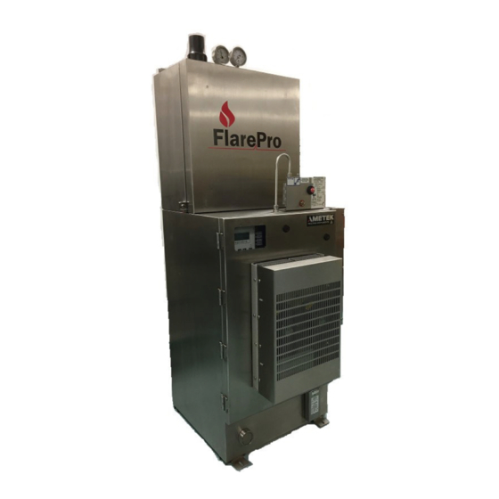
OVERVIEW The FlarePro is a process quadrupole mass spectrometer that provides continuous multi-point monitoring in a stainless steel, gasketed enclosure. The system is cooled and heated by a thermoelectric cooler (TEC), and allows operation at ambient temperatures ranging from -10 °C to +35 °C (single-TEC) or -20 °C to +50 °C (dual-TEC). -
Page 12: Mass Spectrometer Theory
The Sample System serves as a connection between the outside sample environment and the vacuum environment that the mass spectrometer requires. The FlarePro can be equipped with a variety of inlet systems. All of these systems are configured to bring the required number of... -
Page 13: Ei Ionization
Figure 1-1. Ionizer components. As a cloud of electrons accelerates towards the Ionizer Body, the electrons collide with the sample in the center of the ion volume and create ions. Once the ions are formed, they are extracted from the ion region and focused toward the quadrupole Mass Filter by a difference in potential. -
Page 14: Separation
Exit Detector Lens Quadrupole Focus Lens Ionization Chamber - dc + dc Figure 1-2. Mass Filter. 1-4 | FlarePro Process Mass Spectrometer... -
Page 15: Detection
Detection The simplest detection setup consists of a Faraday cup detector. An Electron Multiplier is used for amplified sensitivity. A Faraday cup detector is a closed structure except for an opening that allows the ions to enter. As the ions exit the quadrupole Mass Filter, they strike the detector, creating a current. -
Page 16: Flarepro Overview
FlarePro Overview The FlarePro consists of the following subsystems: • Weatherproof Stainless Steel, Purged Enclosure • Mass Spectrometer • Heated Sample Inlet System • Electrical and Controls System • Vacuum Pumping System • Cooling System • I/O Data Acquisition Option Installation Clearance Requirements •... -
Page 17: Flarepro, 16-Valve Manifold Block (With Single Tec)
FlarePro, 16-Valve Manifold Block (with Single TEC) Overview | 1-7... -
Page 18: Flarepro, 16-Valve Manifold Block (With Dual Tec)
FlarePro, 16-Valve Manifold Block (with Dual TEC) 1-8 | FlarePro Process Mass Spectrometer... -
Page 19: Flarepro, 24-Valve Manifold Block
FlarePro, 24-Valve Manifold Block Overview | 1-9... -
Page 20: Electronics Unit
Faraday cup or Faraday cup / Electron Multiplier detector. Sample System The FlarePro sample system is typically offered with either 16 or 24 valves. One channel (both configurations) is reserved for the process (flare) measurement, and the rest are used with calibration/verification gases. - Page 21 Standard features of both sample systems include: • A heated enclosure, sample selection valves, optional aspirator (for sampling from low pressure processes), and capillary. • A vacuum system containing the analyzer, which is pumped by a Turbo Pump backed with an oil vane pump (Roughing Pump). Overview | 1-11...
-
Page 22: Electrical And Controls
• Power supplies • Relay • Terminal Blocks • Temperature controllers • I/O Racks • Line Filter • Thermal Cut-Off for Inlet Heater Figure 1-4. Power and Signal Distribution panel. 1-12 | FlarePro Process Mass Spectrometer... -
Page 23: Temperature Controllers
This prevents possibly hazardous gases or vapors from entering the enclosure. The FlarePro’s pressurized / purge control system includes a dry contact (2 conductors), which is wired to the on-board computer. This contact closes once proper purge pressure is sensed and opens upon loss of pressurization. -
Page 24: Pressurized / Purge System Components
Pressure and purge flow measurement Contact closure upon loss of pressurization Wiring Conduit for Purge Gas Inlet (1/4" NPTF) Loss-Of- Pressurization Signal Pressurization Visual Indicator Purge Gas Flow Adjustment Valve Figure 1-5. Purge Controller. 1-14 | FlarePro Process Mass Spectrometer... - Page 25 Figure 1-6. Purge Relief Valve (left) and Purge Vent (right) on lower-front of FlarePro. • Calibrated Outlet Orifice The spark-arrested outlet orifice (Figure 1-6) is located at the bottom of the enclosure. It is positioned to ensure cross-flow of pressurization gas.
-
Page 26: Connections
A clean, dry supply of instrument-quality compressed air or other inert gas (e.g., nitrogen is required for operation). A dedicated local pressure regulator is suggested. • Pressure: 65–100 PSIG (550–690 kPa) • Flow: 8 SCFM Max. (227 L/m Max.) 1-16 | FlarePro Process Mass Spectrometer... -
Page 27: Pumps
Both pumps will turn off if they are overheated because of leaks, system failure or mechanical failure. The FlarePro uses a Turbo Pump that is connected directly to the inlet manifold. The Turbo Pump is backed by a Roughing Pump (Figure 1-8). Pump Mounting Vacuum Chamber Clamp &... -
Page 28: Cooling System
The system must function correctly to ensure proper and safe operation of the unit, as well as to generate valid data. The FlarePro heating/cooling system is a modular unit that can be replaced in the field. It is a thermoelectric-type unit (TEC). -
Page 29: Communication
Communication Ethernet Ethernet communications is the required standard interface from the On- Board PC to the remote access PC. The remote access PC uses Remote Desktop software to access information on the on-board computer. Additional Communication Options Modbus Modbus can use Ethernet, RS-232, or RS-485 communication to send data from the On-Board PC. -
Page 30: I/O Data Acquisition System (Optional)
Open or Closed, etc. • Analog input and analog output modules sense or control signals whose value changes within a range, such as temperature, flow, or voltage. OPTO SYSTEM Figure 1-11. Optional I/O Data Acquisition System. 1-20 | FlarePro Process Mass Spectrometer... -
Page 31: Aftermarket Excellence And Long-Term Commitment To Safety And Quality
Aftermarket Excellence and Long-Term Commitment to Safety and Quality Safety is a core value at AMETEK Process Instruments and is our primary consideration in every decision. We believe all accidents, injuries, and occupational illnesses are preventable. We adhere to the highest design and... - Page 32 This page intentionally left blank. 1-22 | FlarePro Process Mass Spectrometer...
-
Page 33: Chapter 2 Specifications
SPECIFICATIONS FlarePro Sensor Celanese Source. Options: Electron Multiplier, 100 AMU or 200 AMU. Performance Mass Position: 0.1 AMU Peak Height: ±2 % per 12 hours Sensitivity: 1 PPM Specifications are valid after a 60-minute warm-up. Mass Range 1–100 AMU and 1–200 AMU Resolution Adjustable to constant peak width (0.5 AMU at 10 % height) - Page 34 110–127 VAC or 220–240 VAC; 50/60 Hz; 20 Amps max. Compressed Gas Clean, dry compressed air or nitrogen Flow: 11 SCFM (156 L/m) maximum (with aspirator) Pressure: 65–100 PSIG (4.5–6.8 BARG) Fitting: 1/4" NPTF Dewpoint:: -40 °C 2-2 | FlarePro Process Mass Spectrometer...
- Page 35 Sample Inlet The FlarePro is designed to accept one heated sample bundle; a boot is provided on the analyzer. The valve manifold inside the oven enclosure includes a 1/8" compression fitting to connect the sample line.
- Page 36 FlarePro Communications Required Remote Access PC: Ethernet Optional Modbus Ethernet, RS-232, or RS-485 Ethernet only Software Mass Spectrometer: Standard Process 2000 Software 2-4 | FlarePro Process Mass Spectrometer...
-
Page 37: Chapter 3 Installation
Sampling Setup and Communication Setup Please refer to the drawing and information provided in Chapter 1 for an overview of the FlarePro (Dimensions, utilities, etc.). Do not open the enclosure unless the area is known to be free of flammable materials, or unless all devices within have been de- energized for at least 30 minutes. -
Page 38: Electronics Installation And In-Line Connections
Electronics Installation and In-line Connections The electronics are shipped in a separate package along with the FlarePro. The electronics will be factory-configured with the I/O board installed and the appropriate cables ready to be installed in the FlarePro enclosure. Connecting the Electronics to Quadrupole Head Power must be off. -
Page 39: Connecting The Electronics To The Dc Line Power
Attach the communications cable to the RS-232 port on the back of the electronics. Set the RS-232 / RS-485 switch on the back of the electronics to RS-232. Make sure that the power cable connection on the back of the electronics is secure and plugged into the power panel. -
Page 40: Leds
Battery-backed RAM has been cleared. Check battery. GREEN Normal operation. COMM LED Indicates the status of communications between the electronics and PC: Flashing GREEN Receiving data from the PC. Electronics unit is inactive. Communications error. 3-4 | FlarePro Process Mass Spectrometer... -
Page 41: Turbopump Control Unit (Dcu)
RF LED Indicates the status of the RF circuit: GREEN The RF amplifier is operating properly. There is a RF failure. YELLOW Automatic RF tune in progress. If you are having a problem in this area, please contact your service engineer. Filament LED Indicates the status of the Filament: GREEN... -
Page 42: Wiring
8 SCFM (227 L/m) maximum at 65–100 PSIG (5.4 to 6.8 BARG). Fitting is 1/4" NPTF. This supplies gas to the purge / pressurization system as well as supplying gas to control the pneumatic valve inlets. 3-6 | FlarePro Process Mass Spectrometer... -
Page 43: Sample System
Sample System The FlarePro sample system consists of a heated inlet enclosure with a sample selection valve manifold assembly. Inlet Enclosure The inlet apparatus is enclosed in a stainless steel housing mounted on the top of the main mass spectrometer enclosure. The housing is insulated and heated. -
Page 44: Calibration Gases
GREEN for the entire time. If the indicator does not remain GREEN, check for purge air leaks (main door not closed properly, enclosure leak insufficient air pressure, etc.). • Apply power to the FlarePro. 3-8 | FlarePro Process Mass Spectrometer... -
Page 45: Chapter 4 Maintenance And Troubleshooting
Roughing / Backing Pump – Oil When the FlarePro is in continuous use, you must change the oil in the rotary vane pump periodically. Type of oil and replacement instructions can be found in the pump manufacturer’s documentation supplied with your analyzer. -
Page 46: Roughing / Backing Pump - Diaphragm
Check the purge relief valve and the purge exhaust spark arrestors and remove any debris or corrosion, or replace the device. These devices are located on the lower front side of the FlarePro enclosure. Two-Year Maintenance At least every two years, check the following items to make sure the analyzer is suitable for the hazardous location: •... -
Page 47: Electronics Unit Maintenance And Troubleshooting
Before connecting the 24 VDC power to the electronics, ensure that the electronics are connected to the sensor. Otherwise, damage to the electronics may occur. Always remove 24 VDC power from the AMETEK electronics before removing the electronics from the sensor. Maintenance and Troubleshooting | 4-3... -
Page 48: Analyzer Head Maintenance
(Filament LED is YELLOW). • If the analyzer is vented to air repeatedly while the Filament is on, the Filament can burn out and yttrium oxide and iridium debris will cover the Source components. FlarePro Process Mass Spectrometer... -
Page 49: Equipment Required To Replace A Filament
Removing the Electronics from the Analyzer Head Always remove 24 VDC power from the AMETEK electronics before removing the electronics from the sensor. • After powering down the electronics unit, carefully use the tightening knobs on the sides of the unit to unlock the electronics from the analyzer head. -
Page 50: How To Remove The Sensor For Service
2. After the system has cooled enough to allow you to work safely, and the pump has stopped rotating, remove the Inlet Box Enclosure cover. 3. Remove the yellow insulation from the bottom of the Inlet Box, taking extreme care to avoid breaking the glass capillary. FlarePro Process Mass Spectrometer... - Page 51 4. Open the Main Enclosure door and disconnect all cables from the process electronics. Loosen the three thumbscrews of the process electronics and carefully lower the electronics away from the sensor. Remove the electronics and set it aside in a safe location. 5.
- Page 52 From the Inlet Box loosen and remove the inlet flange retaining nut. 8. From the Main Enclosure lift and remove the Turbo/Vacuum Chamber assembly, taking extreme care to avoid breaking the glass capillary. 9. Remove the heating jacket from the Vacuum Chamber. FlarePro Process Mass Spectrometer...
- Page 53 10. Remove the nut and graphite ferrule from where the glass capillary enters the Vacuum Chamber. 11. Remove the six bolts/nuts that secure the Sensor to the Vacuum Chamber. Maintenance and Troubleshooting | 4-9...
- Page 54 Sensor or breaking the glass capillary. You can now service the sensor, as described in “Disassembling the Source” and “Replacing the Filament” following this section. Use a 5/64" Allen wrench to remove the ion volume and filament. 4-10 FlarePro Process Mass Spectrometer...
-
Page 55: Sensor Part Numbers
Sensor Part Numbers 9000-277-VE Enclosed Sensor, FlarePro, Faraday 9000-278-VE Enclosed Sensor, FlarePro, Multiplier 7001-948-TE FlarePro Capillary Kit, Includes 20” glass capillary and 3x graphite ferrules. 73328LE FlarePro Ion Volume Repeller 7001-942-KE 1/16” Modified Fitting for FlarePro Closed Source 73174SE Closed Iridium Filament Set... -
Page 56: Replacing The Filament
Barrel Connectors that secure these rods in place, and slide the rods out of the analyzer. Be sure to remove all residual pieces of the old Filament. 4-12 FlarePro Process Mass Spectrometer... - Page 57 Install the new Filament: 1. Install the new Filament being careful not to bend or break the delicate Filament wires. Handle only the shorting tabs on the Filament plate. 2. Tighten the set screws that secure the new Filament in place. 3.
-
Page 58: Disassembling The Closed Source
2. Loosen and remove the three (3) screws that hold the lens together in sandwich form. Be careful not to lose the small ceramic or metal washers from the source; each serves to hold the source in precise alignment. Figure 4-2. Closed/enclosed analyzer head. 4-14 FlarePro Process Mass Spectrometer... -
Page 59: Cleaning The Closed Source
Resource” in this chapter for instructions on cleaning the Source. However, it is often more advantageous to replace the source with a new one. Contact AMETEK to order a new source. The source cannot be disassembled without damaging the filament. -
Page 60: Cleaning The Source
3. Once the head has been checked, replace the ion volume by setting it back on the head (Figure 4-3) and secure it with the set screw. Insert the head into the vacuum chamber and secure it with the six bolts removed earlier. 4-16 FlarePro Process Mass Spectrometer... -
Page 61: Electron Multiplier/V-Stack Detector
Contact AMETEK Process Instruments or your local representative to arrange for factory service to replace the Multiplier. Because of the complexity of the detector flange assembly, AMETEK recommends that the Multiplier be replaced at the factory. Figure 4-3. Breakdown of enclosed ion source. -
Page 62: Troubleshooting The Electronics Unit
Make sure all cables are connected properly to the electronics unit. Make sure that the electronics unit is fully pushed onto the feedthrough contacts. Reset the electronics unit by unplugging the power cable from the unit and plugging it back in. 4-18 | FlarePro Process Mass Spectrometer... - Page 63 Figure 4-5. Analyzer Head pinout, view of flange (atmosphere side). Check the continuity between the Filament feedthroughs. Although protected, the yttria coated iridium Filament will eventually wear out. The best way to determine if this is the case is to check the Filament continuity. −...
-
Page 64: Electronics Unit Communications And Leds
Indicates the status of the Filament: GREEN The Filament is on and is working properly. The Filament is off due to an overpressure, open, or short condition. YELLOW Half of the Filament has failed. 4-20 | FlarePro Process Mass Spectrometer... -
Page 65: Filament Trip/Overpressure And Leds
LED details. Make sure the Filament is turned on by checking the “Light Bulb” icon on the toolbar in the AMETEK System 2000 Software to make sure it is YELLOW (On). Check the Filament status and emission current by accessing the Edit menu on the toolbar and selecting Add Display. - Page 66 This page intentionally left blank. 4-22 | FlarePro Process Mass Spectrometer...
-
Page 67: Chapter 5 Board Replacement
BOARD REPLACEMENT The electronics unit contains six boards (Figure 5-1) that can be replaced in the field if they become damaged or faulty. These boards can be replaced using only a #1 Phillips screwdriver and a 1/4" nut driver. The boards are: •... -
Page 68: Replacing The I/O Board
3. Gently slide out the board disengaging the inside connectors. It may be necessary to gently wiggle the board so that it comes loose. You do not need to remove the cover from the board. 5-2 | FlarePro Process Mass Spectrometer... - Page 69 To replace the I/O board: Gently slide the I/O board into the slot in the back of the electronics unit making sure that you engage the connector on the board with the electronics unit itself. Insert the screws at the top and bottom of the I/O Board Cover, securing it to the electronics unit.
-
Page 70: Replacing The Master Board
3/16" screw for the left side. Using the information that you recorded from your old board, set the RS-485 and RS-232/RS-485 dipswitch settings. Plug in the cables as required. Replace the I/O board. 5-4 | FlarePro Process Mass Spectrometer... -
Page 71: Replacing The Control Board
Replacing the Control Board The Control board is located behind the front heat sink and LED panel on the left side (see Figure 5-1). It is the shorter of the two boards attached to the LED panel. To remove the Control board: Remove the I/O board. - Page 72 Replace the I/O board. There are adhesive gap pads on the back side of the front heat sink and the LED panel to ensure that all fixtures are secure and in place. 5-6 | FlarePro Process Mass Spectrometer...
-
Page 73: Replacing The Scan Board
Replacing the Scan Board The Scan board is located across from the Control board and to its right, behind the LED panel and the front heat sink. It is the longer of the two boards attached to the LED panel. See Figure 5-1. To remove the Scan board: Remove the I/O board. -
Page 74: Replacing The Amp Board
Amp Board Cover RF Board RF board Conductor conductor Guide guide Amp Board Amp Board Shield RF Board Amp board Board Amp Board Cover Front Heat Sink Figure 5-4. Amp board and RF board replacement. 5-8 | FlarePro Process Mass Spectrometer... - Page 75 To replace the Amp board: Secure the Amp board onto the Amp Board Shield using the four (4) 1/4" screws. Attach the Amp Board Cover to the Amp board using the two (2) 1/4" self-tapping sheet metal screws. Insert the RF Assembly into the unit casing and secure using the four (4) 1/4"...
-
Page 76: Replacing The Rf Board
If it is not replaced, the unit will not work. 10. Separate the RF board from the conductor guide. It is very important to remember to retain the conductor guide as it is not part of the replacement board. 5-10 | FlarePro Process Mass Spectrometer... - Page 77 To replace the RF board: Using the 1/4" nut driver, loosely attach the conductor guide to the RF board using the 5/8" standoffs. Plug the analyzer head onto the loosely assembled guide conductor and RF board. Tighten the standoffs using the 1/4" nut driver. Failure to secure the assembly to the analyzer head at this point can result in failure of the unit through cracking of the feedthrough.
- Page 78 This page intentionally left blank. 5-12 | FlarePro Process Mass Spectrometer...
-
Page 79: Chapter 6 Opto 22 Snap Data Acquisitions System
OPTO 22 SNAP Data Acquisition System These instructions describe the steps necessary to set-up the SNAP I/O Data Acquisition System to work with the ProMaxion. Complete information on how to use the modules is provided in the Opto 22 SNAP user manual that you received with the product. -
Page 80: Installation
The B3000-B has the same functionality as the B3000, except that it does not support the Optomux protocol. Customers replacing the B3000 with the B3000-B are required to update to the Process 2000 software AMETEK part number 88175P Process 2000. - Page 81 Opto Brain B3000-B Opto Rack with I/O Modules Opto I/O Modules Input / Output Modules Opto Snap I/O Data Acquisition System | 6-3...
-
Page 82: Configuring The B3000-B Opto Brain
Baud rate switch set to A for 38400 bps baud rate. Termination switches set to “ON” position for 4 wire end of link termination. Upper address set to 8 and lower address set to 3 for a base address of 128. 6-4 | FlarePro Process Mass Spectrometer... - Page 83 Opto Snap I/O Data Acquisition System | 6-5...
- Page 84 6-6 | FlarePro Process Mass Spectrometer...
-
Page 85: Initial Setup Instructions For Opto 22 I/O System
Initial Setup Instructions for Opto 22 I/O System For more information on connecting the Opto 22 brain module to the signal disconnect box, see the signal disconnect wiring diagrams in Chapter 6. Opto Snap I/O Data Acquisition System | 6-7... -
Page 86: Typical Relay Connection Instructions
Not Used Not Used Not Used Not Used Not Used Not Used Not Used Connections and modules used will vary based on your application setup. See the appendix of this manual for your specific configuration. 6-8 | FlarePro Process Mass Spectrometer... -
Page 87: Rs-232 To Rs-485 Converter Cable
RS-232 to RS-485 Converter Cable Figure 6-1. RS-232 to RS-485 converter cable. Power can be applied once the I/O system is connected properly. Opto Snap I/O Data Acquisition System | 6-9... - Page 88 Modules 0, 1, 2, 3 Digital Output Address 129 Modules 12, 13, 14, 15 Analog Input Address 130 Modules 2, 3, 4, 5, 6, 7 Analog Output Address 130 Modules 8, 9, 10, 11, 12, 13 6-10 | FlarePro Process Mass Spectrometer...
-
Page 89: Setting The Device Properties For Digital Input Modules
Setting the Device Properties for Digital Input Modules From the 2000 Software, click the Edit menu and select Device Properties (Figure 6-2). Select your Opto 22 SNAP I/O System device from Select a device to edit. Click OK. The Device Properties dialog box (Figure 6-3) appears. -
Page 90: Add Display For Digital Module
1. To create displays so that you can view the data being monitored, go to the mode display where you want your information viewed (see example in Figure 6-5). To do this, right-click one of the display screens. Figure 6-5. Mode display example. 6-12 | FlarePro Process Mass Spectrometer... - Page 91 a. From the Scan tab (Figure 6-6), click Device and select your digital device. Figure 6-6. Scan tab, Device Properties screen. b. Click the Display tab (Figure 6-7) to configure the parameters for the display. c. Click OK for it to become part of the mode display you have chosen. Figure 6-7.
-
Page 92: Setting Device Properties For Analog Input Modules
For example, if a single analog output module is installed in the first SNAP rack position, the Process 2000 will refer to it as Modules 0 and 1. See B3000 I/O Mapping and Example in this chapter. 6-14 | FlarePro Process Mass Spectrometer... - Page 93 Click the I/O Setup tab for each module position and enter the Type and Name (see example in Figure 6-9). Figure 6-9. I/O Setup tab, Device Properties screen. Continue with “Add Display for Analog Module” to create displays where you can view data. Add Display for Analog Module To create displays so that you can view the data being monitored: 1.
-
Page 94: Digital And Analog Outputs
Digital and Analog Outputs • Refer to Chapter 8 in the 2000 software manual for setting up the Digital Outputs. • Refer to Chapter 9 in the 2000 software manual for setting up the Analog Outputs. 6-16 | FlarePro Process Mass Spectrometer... -
Page 95: Appendix A - Dcu Parameters Settings
Appendix A – DCU Parameters Settings DCU Parameters for High Vacuum System with an Oil Vane Pump and the std normally open vent valve. No Turbo sealing gas valve. 794 Parameter Set 0 Lock Out 1 Open Select 1 allows Parameter Changes 010 Pumping System 0 Off (Default) 1 ON Select 1... - Page 96 This page intentionally left blank. A-2 | FlarePro Process Mass Spectrometer...
- Page 97 Appendix B – OEM Operating Instructions The FlarePro Process Mass Spectrometer is equipped with essential equipment that is not discussed in-depth in this manual. For complete details on operations and maintenance on these components, refer to the manual for the specific...
- Page 98 This page intentionally left blank. B-2 | FlarePro Process Mass Spectrometer...
Need help?
Do you have a question about the FlarePro and is the answer not in the manual?
Questions and answers