
Related Manuals for Ametek TAYLOR HOBSON FORM TALYSURF i PRO Series


Summary of Contents for Ametek TAYLOR HOBSON FORM TALYSURF i PRO Series
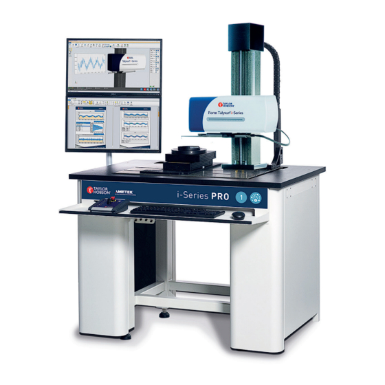
- Page 1 OPER ATOR GUIDE FORM TALYSURF ® FORM TALYSURF ® i-SERIES PRO Range www.taylor-hobson.com © Taylor Hobson Ltd. 2023.
- Page 2 FORM TALYSURF ® i-SERIES PRO Range Introductory operator guide This is Taylor Hobson’s introductory operator guide for the Form Talysurf i-Series PRO, Form Talysurf ® ® WRi PRO & Talysurf PRO. All the specifications in this document are correct at time of production and are subject to change.
-
Page 3: Table Of Contents
Contents Introduction ................. 4 Start up procedure ..............5 Metrology 4.0 software ............. 6 User interface .......................7 Selecting the stylus ..................16 Calibration ..................18 Ball calibration ....................18 Ball calibration procedure - good and bad results .......20 Step height calibration .................21 Calibration artefacts - add, edit or remove ........23 Measurement ................24 2D measurement ....................24 3D measurement ....................26... -
Page 4: Introduction
Introduction The i-Series PRO Range instruments are modular, high precision instruments for the measurement of surface texture, form, radius and contour. They offer the right balance of capability and capacity for virtually every application and budget. All instruments use Taylor Hobson’s renowned Inductive Gauge. All instruments are designed primarily for the measurement of surface texture and form and other recognised metrology functions as determined by Taylor Hobson. -
Page 5: Start Up Procedure
Start up procedure Note Please follow the optimised start up procedure to ensure quick and easy start up of the i-Series PRO and Metrology 4.0: 1. Switch on the i-Series PRO mains supply via switches located on the rear and side of the instrument. 2. -
Page 6: Metrology 4.0 Software
Metrology 4.0 software Metrology 4.0 incorporates all features that are crucial in measurement and analysis. The software has the added ability of having its own fully automated 3D instrument view which allows a true visualisation of the measurement platform on a computer screen. The software platform is split up into 3 distinct sections: Instrument, Analysis and Production Interface This operator guide will focus on all of the main features that make up... -
Page 7: User Interface
User interface Instrument ribbon Control - all instrument Contact - move stylus axes and stages into contact with part Part co-ordinate system Clear all PCS (PCS) Gauge settings - set Gauge calibration options for the gauge Show measurement Show TV view (real time chart display) Scale the view to fit the... - Page 8 Instrument control - move types Moving the axes to arrive at different positons around the measurement platform can be done with the use of the ‘Control’ option. ‘Move to position’, ‘Move by distance’ and ‘Continuous move’ options are available to be selected from the control window. The instrument control dialog box can be displayed by selecting the Control icon in the Positioning section of the Instrument tab.
- Page 9 Move to position in Move by distance in Y-axis Y-axis Rotary - Rotate anti- Rotary - Rotate clockwise continuously clockwise continuously move to ove by Rotary - Rotary - m position distance Tilt - continuous negative Tilt - continuous positive move move Tilt - move to position...
- Page 10 Instrument control - vectored move It is possible to move more than one axes at one time. This can be achieved using a ‘vectored move’. A ‘vectored move’ takes the inputs of all absolute values for the available axes and moves to them inside one routine. The axes will all move with the associated set speeds.
- Page 11 Programming editor Metrology 4.0 software has the built in functionality to create, load and run bespoke measurement and analysis programs to automate the measurement process. Programs can also include variables to further enhance the functionality of routines. Open an existing Create new program program Edit the program...
- Page 12 1. New - To start a new program, click the ‘New’ icon. A blank program tab will appear each time the ‘New’ icon is selected. 2. Open - To load an existing program, tclick the ‘Open’ icon. Browse to the correct ‘.thprog’...
- Page 13 Click the ‘Run program to step’ icon to run the program to a certain position within the program. Click on the desired step to run to and then click the icon. 9. Stop - To stop a program whilst it is running, then click the ‘Stop’ icon. 10.
- Page 14 Configuration ribbon Lock/Unlock Log out Change password User admin User roles Instrument configuration Corrections Configure licence Select language Instrument configuration menu Instrument/system Configure the system’s configurator device performances Add, edit or remove Add or remove stylus calibration artefacts Configure the upper and Center of rotation lower system end stops Configure axis park...
- Page 15 Further icons Stop the current Park instrument instrument operation Exclamation - no Tick corrections/calibration applied Apply saved workspace - Load a workspace from up to 6 layouts available file Save the current Clear workspace and workspace/layout close all windows Save profile Load profile Export settings Import settings...
-
Page 16: Selecting The Stylus
Selecting the stylus To select a stylus, acces the configuration dialog box. 1. Navigate to the ‘Gauge’ section of the instrument ribbon and click on the ‘Settings’ icon. 2. This then brings up a dialog box containing a stylus drop-down list, which is populated with the options available. - Page 17 Removing a stylus To remove a stylus from Metrology 4.0, acces the ‘Gauge’ tab in the ‘Instrument Configuration’ section. 1. Select the ‘Add or remove stylus’ icon. 2. Click ‘Delete’, then confrim the deletion by selecting ‘Yes’. 3. Click ‘OK’ to close the dialog box. The stylus has now been removed from Metrology 4.0.
-
Page 18: Calibration
Calibration Ball calibration (Form Talysurf i-Series PRO / WRi PRO) ® A calibration is required on the gauge to ensure the acurate motion of the stylus has been corrected. This ensures that the measurement is accurate and reliable. Automated calibration procedure steps are below: 1. - Page 19 4. When the calibration routine is complete, the results will appear in the analysis section of Metrology 4.0. 1. Calibration artefact - The artefact in use can be selected using the drop- down list, with information displayed to the right of the list. 2.
-
Page 20: Ball Calibration Procedure - Good And Bad Results
Ball calibration procedure - good and bad results Illustrations below show the differences between good, bad and acceptqable calibration profiles. Bad calibrations can be caused by dirt on calibration artefacts, damaged styli and/or damaged gauge. 1. Good calibration 2. Bad calibration - curves up at edge 3. -
Page 21: Step Height Calibration
Step height calibration (Talysurf PRO) A calibration is required on the gauge to ensure the gain of the gauge has been corrected. This ensures that the measurement is accurate and reliable. Automated calibration procedure steps are below: 1. Navigate to the ‘Gauge’ section of the instrument ribbon and click on the ‘Calibration’... - Page 22 4. When the calibration routine is complete, the results will appear in the analysis section of Metrology 4.0. 1. Calibration artefact - The artefact in use can be selected using the drop- down list, with information displayed to the right of the list. 2.
-
Page 23: Calibration Artefacts - Add, Edit Or Remove
Calibration artefacts - add, edit or remove Adding a new calibration artefact To add a new calibration artfact to Metrology 4.0, acces the ‘Gauge’ tab in the ‘Instrument Configuration’ section. 1. Select the ‘Calibration artefact’ icon. 2. Click ‘New’, and select the type of calibration artefact required from the list. -
Page 24: Measurement
Measurement Making a 2D measurement 2D measurements are used to measure single profiles in the X direction. The measurement procedure steps are below: 1. Navigate to the ‘Measurement toolbar’ and click on the ‘2D X Measurement’ icon. 2. The measurement dialog box will then be displayed. Complete the relevant options and click ‘OK’... - Page 25 1. Measurement name - This is used to distinguish between measurements. The idea is to give the measurement a clear name which can be easily identified later. There is an option to auto-increment from a certain value which can improve the ability to distinguish between measurements and prevent overwrites.
-
Page 26: Measurement
Making a 3D measurement 3D measurements use multiple profiles to generate surfaces. 3D measurements are a result of multiple scans, over a surface using both the X and Y-stages. 1. Navigate to the ‘Measurement toolbar’ and click on the ‘3D Measurement’ icon. 2. - Page 27 1. Measurement name - This is used to distinguish between measurements. The idea is to give the measurement a clear name which can be easily identified later. There is an option to auto-increment from a certain value which can improve the ability to distinguish between measurements and prevent overwrites.
- Page 28 T HE ME T R O L O GY E X P E R T S Taylor Hobson UK Taylor Hobson China Tel: +44 (0)116 276 3771 taylor-hobson-china.sales@ametek.com taylor-hobson.sales@ametek.com Shanghai Office Tel: +86 21 5868 5111-110 Taylor Hobson France Beijing Office...
Need help?
Do you have a question about the TAYLOR HOBSON FORM TALYSURF i PRO Series and is the answer not in the manual?
Questions and answers