Table of Contents
Advertisement
Advertisement
Table of Contents

Related Manuals for Ametek PARSTAT 4000


Summary of Contents for Ametek PARSTAT 4000
- Page 1 PARSTAT 4000 Hardware Manual P/N 224187...
-
Page 2: Table Of Contents
PARSTAT 4000 Hardware Manual Contents Safety Instructions and Symbols ........................4 Cleaning Instructions ............................. 4 Allow the instrument to dry before reconnecting the power cord. 1. INTRODUCTION ........ 4 1.1. General .............................. 5 1.2. Hardware Circuitry ..........................6 1.2.1. Potentiostatic mode ........................6 1.2.2. - Page 3 4.5. Cell Cable Pinouts ........................... 28 5. AVAILABLE OPTIONS ..........................29 5.1 Advanced Auxiliary Interface Option ....................29 5.2 Power Booster Options ........................29 5.3 VersaSTAT LC ultra Low Current Option ..................30 Appendix 1..............................32 PARSTAT 4000 External Current Booster Connections ................ 32...
-
Page 4: Safety Instructions And Symbols
PARSTAT 4000 Hardware Manual Safety Instructions and Symbols This manual contains up to three levels of safety instructions that must be observed in order to avoid personal injury and/or damage to equipment or other property. These are: DANGER Indicates a hazard that could result in death or serious bodily harm if the safety instruction is not observed. -
Page 5: General
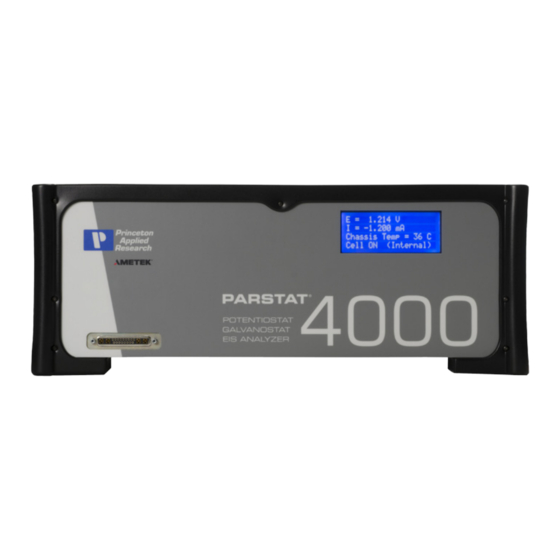
PARSTAT 4000 Hardware Manual 1. INTRODUCTION The PARSTAT 4000 (Figure 1), teamed with the VersaStudio software package, comprises a simple-to-use, flexible, and extremely powerful system for performing a wide range of electrochemical testing. The PARSTAT 4000 is a potentiostat/galvanostat with frequency response analyzer (FRA) contained in a single unit. -
Page 6: Hardware Circuitry
1.2.1. Potentiostatic mode In this mode, the PARSTAT 4000 controls the potential at the working-sense electrode with respect to the reference electrode (see Figure 2). The counter electrode is driven to the potential required (consistent with the + 48 V compliance of the control amplifier) to establish the desired working potential. -
Page 7: Galvanostatic Mode
Figure 2. Potentiostat-Mode Block Diagram 1.2.2. Galvanostatic mode In galvanostatic operation, the PARSTAT 4000 controls the current between the counter and working electrodes at the specified fraction of the selected current range (up to the maximum of the current range; see Figure 2). The counter electrode is driven to the potential required (consistent with the + 48 V compliance of the control amplifier) to establish the desired cell current. -
Page 8: Software
PARSTAT 4000 Hardware Manual Figure 3. Galvanostat-Mode Block Diagram 1.3. Software The PARSTAT 4000 is fully compatible with the VersaStudio software only. PARSTAT 4000 will not operate with any other software other than that specified in this manual most recent... -
Page 9: Maintenance, Service, And Support
PARSTAT 4000 Hardware Manual As soon as you receive your new PARSTAT 4000, inspect it for shipping damage. If any damage is noted, immediately notify Princeton Applied Research and file a claim with the carrier. Save the shipping container for possible inspection by the carrier. -
Page 10: Safety And Component Placement
RF interference and transient sensitivity. 2.1. Safety Considerations 2.1.1. Line Voltage Settings and Fuses The PARSTAT 4000 has a Corcom™ Power Entry Module on the left side of the rear panel. The Corcom module (pictured below) contains the power connector and two line fuses. -
Page 11: Defects And Abnormal Stresses
Do not operate damaged equipment! Tag it to indicate to a potential user that it is unsafe to operate. The PARSTAT 4000’s ground protection is likely to be impaired if, for example, the instrument shows visible damage ... -
Page 12: Ventilation
C) or any of the onboard ventilation fans stops working. 2.2.2. Radio Frequency Interference In a typical application, it is unlikely that the PARSTAT 4000 will act as a source of noticeable RF interference. However, when operated near particularly sensitive equipment, interference from the PARSTAT 4000 could be a problem. -
Page 13: Transient Sensitivity
PARSTAT 4000 Hardware Manual Once the instrument is completely surrounded by the shield (taking care not to unduly restrict ventilation), the only additional requirement is to install low-pass filters where lines pass through the shield (all openings through the shield should be as small as possible). - Page 14 PARSTAT 4000 Hardware Manual Such transients almost always enter the instrument via the line cord. Possible sources include heavy-duty electric motors, RF equipment, diathermy machines, arc welder, spark chambers, and others. Lightning Transients caused by lightning almost always enter the instrument via the line cord.
-
Page 15: Installation
3.1. Enabling the USB port on your PC Some PC manufacturers ship their PCs with the USB port disabled. Check for this before trying to use the PARSTAT 4000. If the port is disabled, follow the manufacturer’s instructions for enabling it. - Page 16 ±2V corresponding to +/- full scale current range, 50Ω output impedance. NOTE: If the PARSTAT 4000 is operating in “float” mode, then all connections to the rear panel must be floating (isolated from ground) as well. If a grounded connection is made to any rear panel connectors (any non-...
-
Page 17: Front Panel
Front Panel Display 3.3. Connecting to the PC and Cell This section gives instructions on connecting the PARSTAT 4000 to the host PC and to electrochemical cell and other equipment. WARNING: For operator and equipment safety, power to all instruments should be off when connecting or disconnecting cables. -
Page 18: Connecting The Cell
Files\Princeton Applied Research\VersaStudio\ folder. 3.3.2. Connecting the Cell To connect the cell cable (part no. 223945) to the PARSTAT 4000: 1. Make sure the POWER switch is off. 2. Match and attach the D connector side of the Cell cable to the front of the PARSTAT 4000, and secure the screws on either side. - Page 19 PARSTAT 4000 Hardware Manual ground point to a Faraday shield for the experimental cell, and is used in some open circuit experiments to form a zero-resistance ammeter (ZRA). PARSTAT 4000 Hardware Manual...
- Page 20 PARSTAT 4000 Hardware Manual 5. The following descriptions and figures explain how to connect a two-, three-, or four-terminal electrochemical cell to the terminals of the PARSTAT 4000 cell cable. a) Batteries, capacitors, resistors, fuel cells, and some sensors are generally connected using a two-terminal connection (Figure 6).
- Page 21 This is necessary to establish the correct polarity relationship at the working electrode versus the reference electrode. 7. After all other connections to the PARSTAT 4000 are complete, experiments can be set up and performed. PARSTAT 4000 Hardware Manual...
-
Page 22: Connecting The External Dummy Cell
PARSTAT 4000 Hardware Manual 3.3.3. Connecting the External Dummy Cell The external dummy cell for the PARSTAT 4000 (part number 3680-1300-06S, pictured below) consists of a 10ohm resistor in series with a 100ohm || 100uF time constant. This dummy cell is utilized in ASTM G106 (Verification of Algorithm and Equipment for Electrochemical Impedance Measurements), and can be used for DC tests as well as EIS testing. - Page 23 PARSTAT 4000 Hardware Manual The sense (gray) and working (green) leads are connected to the working and sense terminals, while the reference (white) and counter (red) leads are connected to the reference and counter terminals. The picture blow demonstrates the connection to the...
- Page 24 PARSTAT 4000 Hardware Manual terminate at those same impedances on Zre and have a diameter of 100ohm, with a maximum Zim of close to 50 ohm (top of semicircle). PARSTAT 4000 Hardware Manual...
- Page 25 PARSTAT 4000 Hardware Manual 4. SPECIFICATIONS AND PINOUTS 4.1. Electronic Specifications 4.1.1 System Performance Minimum Time Base: 1 μs Minimum Potential Step: 1 μV Minimum Current Range 2nA (hardware) Minimum Current Range 40 pA with 50X gain ...
- Page 26 PARSTAT 4000 Hardware Manual 4.1.6. Voltage Measurement Voltage Range + 10 V Minimum Voltage Resolution 1.5 µV (2.5 V range, X50 gain applied) Voltage Accuracy + 0.2% reading, + 2 mV 4.1.7. Current Measurement Current Ranges 13 decades, 20A to 40pA...
- Page 27 PARSTAT 4000 Hardware Manual 4.2. Physical and Power Specifications Computer Interface Universal Serial Bus (USB) Weight 23 kg (50 lbs) Dimensions 51.5 cm W x 49 cm D x 19.5 cm H (20.25 in x 19.25 in x 7.75 in ) Power Requirements ...
-
Page 28: Auxiliary Interface Pinouts
Using the VersaStudio software, an experiment can be held, waiting on this TTL trigger input signal to be read. DISPENSE When using the PARSTAT 4000 with a Model 303 or 303A Static Mercury Drop Electrode (SMDE) via a Model 507... -
Page 29: Available Options
Each current booster includes an external power supply interfaced to additional internal circuitry of the PARSTAT 4000 system via the rear panel. Once connected, the system can be operated in either boosted mode or normal mode depending on a switch setting at the rear panel, as well as some cell cable changes. -
Page 30: Versastat Lc Ultra Low Current Option
PARSTAT 4000 Hardware Manual Note: In boosted mode, the system is required to stay on a single current range, and is limited in this mode to current measurements at a resolution of 16 bits for the boosted range. This option has components that are built into the base unit, so it must be purchased at the same time along with the base unit, or at a later time by returning the base unit to a qualified Princeton Applied Research Service Center for installation and calibration. - Page 31 PARSTAT 4000 Hardware Manual Advanced Measurement Technology, Inc. a/k/a Princeton Applied Research, a subsidiary of AMETEK®, Inc. WARRANTY Princeton Applied Research* warrants each instrument of its own manufacture to be free of defects in material and workmanship. Obligations under this Warranty shall be limited to replacing, repairing or giving credit for the purchase price, at our...
-
Page 32: Appendix 1
No correction factor is required as with some other power booster options. The PARSTAT 4000 functions on a fixed current range of 2mA when operating in “Booster Mode” with the KEPCO power supply. The interface board scales the current signals from the KEPCO to allow current measurements to ±... - Page 33 The PARSTAT 4000 and KEPCO connect to the cell (electrochemical cell, battery, etc.) by two marked cables, 223873 for the KEPCO and 223859 for the PARSTAT 4000 (replacing the normal cell cable used for “Normal” mode). All the interconnections for the PARSTAT 4000 and KEPCO are shown below.
- Page 34 PARSTAT 4000 Hardware Manual KEPCO Front-Panel Setup The MODE switch on the front panel of the KEPCO should be set to Voltage mode (left position). The Voltage CONTROL switch (red toggle on left side) should be in the OFF (down) position.
- Page 35 5 watts. Dummy Cell Connections 1. Ensure the power is off on both the PARSTAT 4000 and KEPCO. 2. Connect dummy cell (resistor) as shown above with Counter/Reference connected to one side of the resistor, and Working/Sense connected to the opposite side.
Need help?
Do you have a question about the PARSTAT 4000 and is the answer not in the manual?
Questions and answers