Table of Contents
Advertisement
Advertisement
Table of Contents

Related Manuals for Ametek Solartron Analytical ModuLab XM ECS


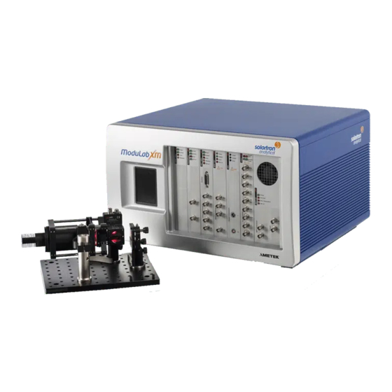
Summary of Contents for Ametek Solartron Analytical ModuLab XM ECS
- Page 1 Electrochemical System INSTALLATION GUIDE...
- Page 3 Solartron Analytical Ltd 5 Ashville Way, Molly Millars Lane, Wokingham, Berkshire, RG41 2PL, UK Tel +44 (0) 1252 556 800 DECLARATION OF CONFORMITY The directives covered by this declaration 73/23/EEC Low Voltage Equipment Directive, amended by 93/68/EEC 89/336/EEC Electromagnetic Compatibility Directive, amended by 92/31/EEC & 93/68/EEC Product(s) ®...
- Page 5 GENERAL SAFETY PRECAUTIONS The equipment described in this manual has been designed in accordance with EN61010 "Safety requirements for electrical equipment for measurement, control and laboratory use", and has been supplied in a safe condition. To avoid injury to an operator or service technician the safety precautions given below, and throughout the manual, must be strictly adhered to, whenever the equipment is operated, serviced or repaired.
- Page 6 General Safety Precautions (continued from previous page) Symbol Meaning Safety hazard involving heavy weights. A numerical value for the amount of weight may appear alongside this symbol. Take care when handling and carrying. Follow the manufacturer’s instructions, and ask for assistance if necessary. NOTES, CAUTIONS AND WARNINGS For the guidance and protection of the user, Notes, Cautions and Warnings appear throughout the manual.
- Page 7 DISPOSAL AND RECYCLING OF EQUIPMENT IN THE EUROPEAN UNION Solartron Analytical is an environmentally friendly company, committed to the disposal and recycling of electrical and electronic waste according to procedures that have the least possible impact on health and the environment. The company supports the disposal of equipment according to the EU directive on Waste Electrical and Electronic Equipment (WEEE).
- Page 8 Text Conventions ® The following text conventions are used in the ModuLab XM documentation: • Bold text is used for headings. • Blue text is used for names and titles of features of the ModuLab XM hardware and software, when it is required that the user, at this point, should find these features on the system.
-
Page 9: Table Of Contents
ModuLab XM ECS Electrochemical System: Installation Guide Contents ® INTRODUCING MODULAB XM ECS ............1-1 ® THE MODULAB XM ECS DOCUMENTATION ........ 1-1 SYSTEM OVERVIEW ................ 1-1 MODULAB XM CHASSIS ..............1-2 EXTERNAL POWER BOOSTERS ............. 1-4 MODULE SUMMARY ................ 1-7 1.5.1 Module Identifiers ................ - Page 10 Contents ModuLab XM ECS Electrochemical System: Installation Guide CHECKING THE SYSTEM COMMUNICATIONS ......2-14 MANUAL ADDITION OF EQUIPMENT ..........2-20 ADVANCED SETUP ................ 2-22 2.9.1 Connection to a Corporate Network ..........2-22 2.9.2 Hardware IP Addressing ..............2-26 2.10 REBOOTING THE SYSTEM ............2-33 INSTALLATION TESTS................
- Page 11 Contents ModuLab XM ECS Electrochemical System: Installation Guide POTENTIOSTAT / FRA ACCURACY ..........5-3 5.3.1 Core Potentiostat Accuracy ............... 5-3 5.3.2 FRA Accuracy ................... 5-3 CHASSIS SPECIFICATION ............... 5-3 TYPICAL PC CONFIGURATION ............5-4 HARDWARE ORDERING INFORMATION ........5-4 SOFTWARE ORDERING INFORMATION ........5-4 EXTERNAL BOOSTERS ..............
- Page 12 Contents ModuLab XM ECS Electrochemical System: Installation Guide Figure 2-8 PC connected to ModuLab XM Chassis through network ....2-23 Figure 2-9 Multiple PCs connected to ModuLab XM Chasses through network 2-24 Figure 2-10 Multiple PCs assigned to potentiostat groups in a chassis ... 2-24 Figure 2-11 PC connected to ModuLab XM and network using two network cards 2-25...
-
Page 13: Introducing Modulab Xm Ecs
ModuLab XM ECS Electrochemical System: Installation Guide ® 1. Introducing ModuLab XM ECS ® THE MODULAB XM ECS DOCUMENTATION ® When you receive delivery of your ModuLab XM ECS system, you will need to work through the manuals in the following order: •... -
Page 14: Modulab Xm Chassis
Introducing ModuLab XM ECS ModuLab XM ECS Electrochemical System: Installation Guide The modules are mounted in slots in the chassis and can be removed and replaced, so that you can design and modify the system according to your requirements (although it is normally supplied with the modules assembled and configured for a specific purpose). - Page 15 Introducing ModuLab XM ECS ModuLab XM ECS Electrochemical System: Installation Guide Figure 1-1 ModuLab XM front view Figure 1-2 ModuLab XM front view with cover and modules removed 21006002_AD 11/06/14...
-
Page 16: External Power Boosters
Introducing ModuLab XM ECS ModuLab XM ECS Electrochemical System: Installation Guide Figure 1-3 ModuLab XM rear view EXTERNAL POWER BOOSTERS External power boosters are available for applications where the current exceeds the 2A maximum capacity of the internal booster. Four models of the external booster are available, identified by their front panel labels which indicate their capacity as follows: •... - Page 17 Introducing ModuLab XM ECS ModuLab XM ECS Electrochemical System: Installation Guide All four versions have the same design, and the front and rear panels are shown in Figures 1-4 and 1-5. Figure 1-4 External booster front panel 21006002_AD 11/06/14...
- Page 18 Introducing ModuLab XM ECS ModuLab XM ECS Electrochemical System: Installation Guide Figure 1-5 External booster rear panel 21006002_AD 11/06/14...
-
Page 19: Module Summary
Introducing ModuLab XM ECS ModuLab XM ECS Electrochemical System: Installation Guide MODULE SUMMARY The modules which can be fitted to the chassis are as follows: • The potentiostat is the basic component of the ModuLab XM system that, on its own, is able to perform DC electrochemical experiments on a wide range of batteries, fuel cells and electrochemical cells. -
Page 20: Module Identifiers
Introducing ModuLab XM ECS ModuLab XM ECS Electrochemical System: Installation Guide The external booster is used as an alternative to the internal booster, not an addition. It is possible to have both of them installed in the same potentiostat group, but they cannot both be used at the same time. ... -
Page 21: Cables
Introducing ModuLab XM ECS ModuLab XM ECS Electrochemical System: Installation Guide 1.5.2 Cables The cables for connecting the ModuLab XM system to the cell are shown in Table 1-2. Table 1-2 Cables Module / Part Number Description Channel 20870301 RE cable from Pstat/HV to cell Pstat/HV 20870323 CE / WE cable from Pstat/HV to cell (except when... -
Page 22: Potentiostat Groups And Communication
Introducing ModuLab XM ECS ModuLab XM ECS Electrochemical System: Installation Guide 1.5.3 Potentiostat Groups and Communication The modules are fitted to slots in the chassis so that they are arranged in groups. Each group has a potentiostat as the core module, and is known as a potentiostat group. -
Page 23: Measurements On Floating And Grounded Cells
Introducing ModuLab XM ECS ModuLab XM ECS Electrochemical System: Installation Guide 1.5.5 Measurements on Floating and Grounded Cells The group common reference point LO can be set to internal or external grounding, using a switch that is controlled from the ModuLab XM Software. ... - Page 24 Introducing ModuLab XM ECS ModuLab XM ECS Electrochemical System: Installation Guide PSTAT Figure 1-7 External grounding (LO and WE floating, cell grounded) If external grounding is used, LO and WE can have voltages up to100V depending on the modules fitted. ...
-
Page 25: Module Functions
Introducing ModuLab XM ECS ModuLab XM ECS Electrochemical System: Installation Guide MODULE FUNCTIONS 1.6.1 XM Potentiostat Module The potentiostat performs experiments on a test specimen, normally a battery, fuel cell, or other electrochemical cell. When used on its own in the absence of other modules, it can run DC experiments, but when combined with an FRA it can also measure impedance. -
Page 26: Xm Frequency Response Analyzer Module
Introducing ModuLab XM ECS ModuLab XM ECS Electrochemical System: Installation Guide Error (Red) Indicates an error state under the following conditions: • The system has been overloaded or has exceeded the safety limit. • A firmware upgrade has been successfully completed, but the system needs to be rebooted. - Page 27 Introducing ModuLab XM ECS ModuLab XM ECS Electrochemical System: Installation Guide In both versions, the front panel connectors are as follows: Provides monitoring of the generated output signal, identical to the signal that is passed to the potentiostat. However, it is bigger than the signal applied to the cell because the potentiostat attenuates the signal by 10 or 100, depending on the programmed signal amplitude.
-
Page 28: Xm High Voltage Modules
Introducing ModuLab XM ECS ModuLab XM ECS Electrochemical System: Installation Guide 1.6.3 XM High Voltage Modules The potentiostat has a voltage span of ±8V, which may not be enough for some applications, for example measurements of a battery or fuel cell stack. In this case, high voltage modules may be added to the system, to raise the voltage to suitable levels. -
Page 29: Xm Femto Ammeter Module
Introducing ModuLab XM ECS ModuLab XM ECS Electrochemical System: Installation Guide Comms (Green) Indicates that a link has been established between the HV module and the potentiostat. Error (Red) Indicates a current overload. This LED comes on briefly when the system is switched on, then goes off when it has booted up. -
Page 30: Xm Internal Booster Module
Introducing ModuLab XM ECS ModuLab XM ECS Electrochemical System: Installation Guide The femto ammeter has the following front panel connectors: Connects to the working electrode of the cell to measure the current. This connector is used instead of the corresponding WE socket on the potentiostat. A common reference point for modules in a potentiostat group. - Page 31 Introducing ModuLab XM ECS ModuLab XM ECS Electrochemical System: Installation Guide The booster has the following front panel connectors: • For connection to the potentiostat: Working electrode A common reference point for modules in a potentiostat group. Section 1.5.4, Group Common Reference Voltage.
-
Page 32: External Power Boosters
Introducing ModuLab XM ECS ModuLab XM ECS Electrochemical System: Installation Guide Over Temperature (Red) Indicates that the booster has overheated. When this condition occurs, the experiment will stop running, under control of the ModuLab XM software, and can to be restarted from the software when the fault has been rectified, but only after the booster has cooled down. - Page 33 Introducing ModuLab XM ECS ModuLab XM ECS Electrochemical System: Installation Guide The booster front panel is shown in Figure 1-8: STOP STOP Figure 1-8 External booster front panel The connectors are as follows: • For connection to the potentiostat: Counter electrode Working electrode A common reference point for modules in a potentiostat group.
- Page 34 Introducing ModuLab XM ECS ModuLab XM ECS Electrochemical System: Installation Guide The booster status is indicated by the front panel LEDs as follows: Power (Green) Indicates that the booster is powered up. Overload (Red) Indicates that the booster has operated beyond its normal capacity.
- Page 35 Introducing ModuLab XM ECS ModuLab XM ECS Electrochemical System: Installation Guide WARNING It is important to ensure that the experiment has paused from the ModuLab XM software, otherwise when the Stop button is pressed in Step 4 of this sequence, the feedback paths will be re- established causing a power surge.
-
Page 37: Assembling The System
ModuLab XM ECS Electrochemical System: Installation Guide 2. Assembling the System THE APPROACH TO SYSTEM ASSEMBLY This chapter describes how to assemble a ModuLab XM ECS System so that it is capable of running experiments and is ready for the installation tests. The system comprises a range of modules mounted in a 4-slot or 8-slot chassis and is controlled via Ethernet from a suitable PC running the ModuLab XM ECS software. -
Page 38: Pc System Requirements
Assembling the System ModuLab XM ECS Electrochemical System: Installation Guide 2.1.1 PC System Requirements The system requirements for the installation of the ModuLab XM software on a PC are given in Table 2-1 below: Table 2-1 PC System Requirements Hardware / Software Requirement Pentium IV or equivalent 2GB RAM... - Page 39 Assembling the System ModuLab XM ECS Electrochemical System: Installation Guide 220-240V mains supply - T5A H 250V (5 A time lag, high breaking capacity, 250 V rated) 100-120V mains supply – T10A H 250V (10 A time lag, high breaking capacity, 250 V rated) Figure 2-1 Mains power input connector...
-
Page 40: Configuring The Pc Ethernet Interface
Assembling the System ModuLab XM ECS Electrochemical System: Installation Guide 6. The modules are identified by their front-panel labels and will have been installed by Solartron, according to your specification. If any of the modules need to be changed, switch off the system and unplug it from the mains, then proceed with the module installation. -
Page 41: Configuring Ethernet For Windows Xp
Assembling the System ModuLab XM ECS Electrochemical System: Installation Guide 2.3.1 Configuring Ethernet for Windows XP To configure the PC Ethernet interface for Windows XP Professional with the Control Panel set to Category view, proceed as follows: 1. At the PC, click to display the Control Panel. - Page 42 Assembling the System ModuLab XM ECS Electrochemical System: Installation Guide This will display the dialog box entitled Local Area Connections Properties. 5. Select the Internet Protocol (TCP/IP) service and click on Properties, to display the dialog box entitled Internet Protocol (TCP/IP) Properties.
-
Page 43: Installing The Modulab Xm Ecs Software
Assembling the System ModuLab XM ECS Electrochemical System: Installation Guide 6. Normally the system will work correctly with automatic IP addressing, but if there are problems, select Use the following IP address, then enter the following values: • An IP address in the range 169.254.254.120 to 169.254.254.254. •... -
Page 44: Microsoft .Net Framework
Assembling the System ModuLab XM ECS Electrochemical System: Installation Guide 2.4.1 Microsoft .Net Framework The ModuLab XM application is built on a software development platform called .Net Framework, which must be installed on your computer to enable ModuLab XM to be installed. The required components are: Microsoft .Net Framework Version 4 Other versions of .Net Framework may already be installed for use with other applications, but these are irrelevant to ModuLab XM, and the component listed... -
Page 45: Installing The Modules In The Chassis
Assembling the System ModuLab XM ECS Electrochemical System: Installation Guide INSTALLING THE MODULES IN THE CHASSIS The ModuLab XM system is normally supplied with all the modules installed, according to the customer’s requirements, so that it is only necessary to check that the modules are present and in the correct order, then connect the PC to the ModuLab XM using the Ethernet. - Page 46 Assembling the System ModuLab XM ECS Electrochemical System: Installation Guide 2. Undo the bolts (4) in each corner at the back of the case and remove the front cover (3). 3. To remove a module, undo the upper and lower screws next to the ejectors (5), then push the ejectors (the top one upwards and the bottom one downwards) so that the module is pulled out slightly and disengages from the socket in the backplane.
-
Page 47: Assembling The Modules In The Correct Order
Assembling the System ModuLab XM ECS Electrochemical System: Installation Guide 2.5.1 Assembling the Modules in the Correct Order Where potentiostats alone are used, they may be inserted into adjacent slots in any order. However, when installing other modules so that they operate as a potentiostat group, it is important to observe the following rules: •... -
Page 48: Unused Modules
Assembling the System ModuLab XM ECS Electrochemical System: Installation Guide In these examples, the modules are arranged from left to right as follows: • Group 1. A frequency response analyzer alongside a potentiostat to perform DC and AC measurements. • Group 2. A frequency response analyzer alongside a potentiostat, followed by an HV 100 module, femto ammeter and 2A internal booster, for DC and AC measurements at high voltage, and either at high impedance or high power. - Page 49 Assembling the System ModuLab XM ECS Electrochemical System: Installation Guide 2. Connect the chassis to the AC supply and switch it on, if it is not already running, making sure the mains voltage and fuses are correct. The Solartron logo will appear on the ModuLab XM front panel LCD. The power LEDs (green) on the potentiostats and FRAs will flash during a self-test, and will then come on continuously when the test is successfully completed.
-
Page 50: Checking The System Communications
Assembling the System ModuLab XM ECS Electrochemical System: Installation Guide CHECKING THE SYSTEM COMMUNICATIONS To check the system communications, proceed as follows: 1. Make sure the ModuLab XM and PC are switched on and connected to each other through the Ethernet. ... - Page 51 Assembling the System ModuLab XM ECS Electrochemical System: Installation Guide This is followed by the opening screen as follows: This screen has a left-hand navigation panel containing a structure of items representing the most recently opened project. The Getting Started project appears by default when ModuLab XM is first installed and run.
- Page 52 Assembling the System ModuLab XM ECS Electrochemical System: Installation Guide checking the system communications, but it will be convenient to open the Getting Started project because it will be needed for the Installation Tests. Chapter 3, Installation Tests Details of how to open projects are in the User Guide.
- Page 53 Assembling the System ModuLab XM ECS Electrochemical System: Installation Guide 6. Click the Search button, and the system will identify all the items of equipment as follows: • Search button will disappear and will be replaced with a tabulated list of equipment.
- Page 54 Assembling the System ModuLab XM ECS Electrochemical System: Installation Guide do not have Ethernet interfaces, and communicate with the PC through the potentiostat, using a link in the backplane. If there are multiple chasses, the system will initially be unable to determine the correct location of all the potentiostat groups and will place them under the first chassis in the navigation panel.
- Page 55 Assembling the System ModuLab XM ECS Electrochemical System: Installation Guide • Advanced. This feature enables you to change the address of the chassis display panel hardware, and should normally only be used if there is a conflict of addresses within the system. ...
-
Page 56: Manual Addition Of Equipment
Assembling the System ModuLab XM ECS Electrochemical System: Installation Guide If the test is successful, a list of modules in the group, followed by details of the potentiostat, will appear as follows: A list of modules will also appear on the chassis front panel display, and will be updated to reflect any changes since the last time the button was pressed. - Page 57 Assembling the System ModuLab XM ECS Electrochemical System: Installation Guide 2. Click on the System tab. 3. Click on the Equipment library, in the left-hand navigation panel, and expand it to display the sub-items. 4. Right-click on the parent of the item that needs to be added, and a drop-down menu will appear.
-
Page 58: Advanced Setup
Assembling the System ModuLab XM ECS Electrochemical System: Installation Guide ADVANCED SETUP This chapter has so far described the installation process on the basis that a PC is available alongside a single ModuLab XM chassis for direct connection through a dedicated Ethernet socket as follows: Network Uplink... - Page 59 Assembling the System ModuLab XM ECS Electrochemical System: Installation Guide 2.9.1.1 Single Chassis, Single Local PC Control, ModuLab XM Network Access In the following configuration, a ModuLab XM chassis is controlled directly from the PC, but the upper socket of the chassis is connected to the network. Network Network Uplink...
- Page 60 Assembling the System ModuLab XM ECS Electrochemical System: Installation Guide 2.9.1.3 Multiple Chasses, Multiple PCs, Network Control If the network has sufficient data capacity, it can be connected to multiple ModuLab XM chasses and they can be controlled from any PC on the network, provided that each potentiostat group is under the control of a single PC at any given time.
- Page 61 Assembling the System ModuLab XM ECS Electrochemical System: Installation Guide NOTE: In cases where multiple PCs can access a ModuLab XM system through a network, control is established from any given PC, through the ModuLab XM software, on a first-come first-served basis. To relinquish control and make the equipment available to another PC, you have to close the project.
-
Page 62: Hardware Ip Addressing
Assembling the System ModuLab XM ECS Electrochemical System: Installation Guide 2.9.2 Hardware IP Addressing The ModuLab XM system is supplied with the IP addresses of the chassis display panel and modules set at their default values. Table 2-2, Section 2.3, Default IP Addresses for ModuLab XM. The default addresses will be adequate for most purposes but may need to be changed in certain circumstances, for example: •... - Page 63 Assembling the System ModuLab XM ECS Electrochemical System: Installation Guide the chassis where a module may be fitted. Only the display panel, potentiostats and FRAs need to be given IP addresses. The other module types do not have Ethernet interfaces. The procedures for changing hardware addresses are slightly different for the chassis display panel and modules.
- Page 64 Assembling the System ModuLab XM ECS Electrochemical System: Installation Guide 2.9.2.2 Changing the Module Addresses The potentiostats and FRAs are each programmed with HTML code so that details of the modules can be displayed and modified from your Web browser. The module addresses can be changed as follows: 1.
- Page 65 Assembling the System ModuLab XM ECS Electrochemical System: Installation Guide 5. Close the ModuLab XM ECS software, but leave the Web page open. 6. Click on the Ethernet button to display the Ethernet Configuration page as follows: NOTE: Reset button restores the fields to their current values, cancelling whatever has been typed.
- Page 66 Assembling the System ModuLab XM ECS Electrochemical System: Installation Guide A dialogue box will appear, asking for a user name and password as follows: NOTE: The warning about the insecure transmission of the username and password appears as a security feature in some versions of Internet Explorer, but is of no consequence in this application.
- Page 67 Assembling the System ModuLab XM ECS Electrochemical System: Installation Guide 1. Display the appropriate Instrument Web Page from the Potentiostat Group Setup (as in Changing the Module Addresses). 2. Click on the Passwords button to display the following page: Network Password section is for changing the module address, and the Firmware Upgrade section is for upgrading the module firmware (by clicking...
- Page 68 Assembling the System ModuLab XM ECS Electrochemical System: Installation Guide 3. In the appropriate section, type the old password, then the new password, then confirm the new password and click Submit. A prompt will appear, asking for a user name and password as follows: 4.
-
Page 69: Rebooting The System
Assembling the System ModuLab XM ECS Electrochemical System: Installation Guide 2.10 REBOOTING THE SYSTEM If, for any reason, the ModuLab XM system needs to be rebooted (for example after a firmware upgrade, or after a network cable has been temporarily disconnected), proceed as follows: 1. -
Page 71: Installation Tests
ModuLab XM ECS Electrochemical System: Installation Guide 3. Installation Tests When the installation has been completed and the PC is communicating with the modules, the system needs to be tested by connecting the modules to an appropriate test cell, in which a simple electrical circuit represents an electrochemical cell. -
Page 72: The Test Cells
Installation Tests ModuLab XM ECS Electrochemical System: Installation Guide NOTE The FRA, if fitted, does not connect to the test cell. Instead it communicates with the potentiostat internally, providing the alternating signal for AC measurements. THE TEST CELLS There are two test cells for use with the ModuLab XM system, and they are used to test particular modules in the system: •... - Page 73 Installation Tests ModuLab XM ECS Electrochemical System: Installation Guide Figure 3-2 ModuLab 0.1 ohm Cell 21006002_AD 11/06/14...
-
Page 74: Dc Responses To Test Cells
Installation Tests ModuLab XM ECS Electrochemical System: Installation Guide 3.2.1 Time Domain/DC Responses to Test Cells The ModuLab Test Cell has a circuit made up of resistors and capacitors, and the circuit diagram is printed on the cover (Figure 3-1). This circuit is effectively a series of resistors when a DC voltage is applied, with a total resistance of 11.6kΩ. - Page 75 Installation Tests ModuLab XM ECS Electrochemical System: Installation Guide A typical Bode plot is shown in Figure 3-4: Figure 3-4 Test cell response to AC input (Bode plot) A typical complex plane plot is shown in Figure 3-5. Figure 3-5 Test cell response to AC input (complex plane plot) The real and imaginary components of impedance give a locus of points which vary with the frequency (f).
-
Page 76: Potentiostat Test
Installation Tests ModuLab XM ECS Electrochemical System: Installation Guide POTENTIOSTAT TEST In this example, a potentiostat is connected to the ModuLab Test Cell as shown in Figure 3-6. The potentiostat stimulates the cell by applying a DC voltage to the counter electrode, and measures the current through the working electrode. - Page 77 Installation Tests ModuLab XM ECS Electrochemical System: Installation Guide 2. Make sure the Project tab is selected at the bottom of the left-hand navigation panel, and click on the plus (+) symbol alongside the Getting Started project to expand it, then expand the sub-elements to reveal the structure as follows: Underneath the Getting Started project there is an experiment called...
- Page 78 Installation Tests ModuLab XM ECS Electrochemical System: Installation Guide Each row in the tabulated list of potentiostat groups contains a potentiostat and a number of optional modules. The tabulated list will depend on the groups installed in your system, and all groups that are coloured green will be suitable for use with the experiment.
- Page 79 Installation Tests ModuLab XM ECS Electrochemical System: Installation Guide 6. Click on the drop down list box and select the potentiostat group that you wish to use for this experiment, as follows: 7. Click on Linear Sweep Voltammetry. This represents a DC step within the experiment, which defines how measurements are to be taken over a given period of time.
- Page 80 Installation Tests ModuLab XM ECS Electrochemical System: Installation Guide The two graphs on the right are for illustration and setup purposes only, as follows: • The upper graph is a representation of the waveform, and explains the meaning of the parameters in the setup. •...
- Page 81 Installation Tests ModuLab XM ECS Electrochemical System: Installation Guide A structure of data items will appear in the left-hand navigation panel, with Pstat Group 1 item automatically selected, and the results will be displayed as follows: This screen displays a graph of current density (A/cm ) against voltage, representing the current produced at the working electrode in response to the applied voltage at the counter electrode.
- Page 82 Installation Tests ModuLab XM ECS Electrochemical System: Installation Guide 11. The number and type of graphs will depend on how they have been set up in the User Preferences, but you can change them, and you can display tabulated data, from the Axes sub-screen.
-
Page 83: Auxiliary Channel Dc Test
Installation Tests ModuLab XM ECS Electrochemical System: Installation Guide 3.3.1 Auxiliary Channel DC Test This test can be performed only if auxiliary channels are available on the potentiostat. To test the auxiliary channels, proceed as follows: 1. Click on the Potentiostat Test, in the left-hand navigation panel, to display the Start Experiment... - Page 84 Installation Tests ModuLab XM ECS Electrochemical System: Installation Guide 2. Click on the Setup item, under Potentiostat Test, and make sure the correct potentiostat group is selected in the Hardware Requirements sub-screen, as follows: 3. Expand the Potentiostat Experiment Setup sub-screen, and under Enable Auxiliary Voltage...
- Page 85 Installation Tests ModuLab XM ECS Electrochemical System: Installation Guide 4. Click on Potentiostat Test, in the left-hand navigation panel, to return to the Start Experiment screen and you will see that the auxiliary channels have become a requirement for the experiment, indicated by a tick in the AuxV column of the Experiment Hardware...
- Page 86 Installation Tests ModuLab XM ECS Electrochemical System: Installation Guide 6. Run the experiment, same as for the Potentiostat Test, and observe the results. If the graphics have already been set up to display auxiliary channels, they will appear as separate traces on the graphs, each with their own legend. If this does not occur, it will be necessary to edit the Axes sub-screen.
- Page 87 Installation Tests ModuLab XM ECS Electrochemical System: Installation Guide 7. Under Channels, check the boxes for the auxiliary channels that are to display data, as follows: 8. Click the Refresh button in the Axes sub-screen, to display the auxiliary channel results as additional traces on the graph, as follows: In this example there are five traces altogether, although some of them are similar enough to be superimposed on each other.
-
Page 88: Xm Fra Test
Installation Tests ModuLab XM ECS Electrochemical System: Installation Guide 9. When finished, unless you want to continue using the auxiliary channels for further experiments, disconnect the cables and disable the channels by clearing the check boxes in the Potentiostat Experiment Setup sub-screen (Step 3). - Page 89 Installation Tests ModuLab XM ECS Electrochemical System: Installation Guide 2. Click on Setup, under Test, to display the experiment setup screen as follows: 3-19 21006002_AD 11/06/14...
- Page 90 Installation Tests ModuLab XM ECS Electrochemical System: Installation Guide 3. In the Hardware Requirements sub-screen, click the Advanced check box to display the additional fields as follows: This has been set up with the Potentiostat Group to use field set to Custom, so that the experiment does not depend on any specific hardware, and the FRA model has been set to 300kHz.
- Page 91 Installation Tests ModuLab XM ECS Electrochemical System: Installation Guide 4. In the Potentiostat Group to use field, select the group that you wish to use for this experiment. The fields representing the optional modules will become greyed out, because the only modules available are the ones that were installed for this potentiostat group, within the Equipment library, when checking the system communications, so the screen becomes as follows: ...
- Page 92 Installation Tests ModuLab XM ECS Electrochemical System: Installation Guide 5. Click on the step called Potentiostatic Impedance in the left-hand navigation panel. This will display a set of windows, similar to those already displayed for the Potentiostat Test, except that there will be an additional panel in the central column called Impedance Setup, and the screen will be as follows:...
- Page 93 Installation Tests ModuLab XM ECS Electrochemical System: Installation Guide 7. Make sure all the connections are in place, according to the cell connections diagram, then run the experiment as described for the Potentiostat Test. The results will appear as the experiment proceeds, and on completion it will be as follows: The results are displayed as a Bode plot of impedance and phase angle against frequency, because this is the default graphic display for a potentiostatic...
- Page 94 Installation Tests ModuLab XM ECS Electrochemical System: Installation Guide 8. Change the Graph 1 field in the Axes sub-screen to Complex (Z), then press Refresh button, to redisplay the results as follows: This is a complex plane plot of the real and imaginary components of impedance.
-
Page 95: Auxiliary Channel Ac Test
Installation Tests ModuLab XM ECS Electrochemical System: Installation Guide 3.4.1 Auxiliary Channel AC Test This test requires an FRA to be present, and auxiliary channels must be fitted to the potentiostat. To perform this test, proceed as follows: 1. In the left-hand navigation panel, click on the Setup item, under Test, to... - Page 96 Installation Tests ModuLab XM ECS Electrochemical System: Installation Guide 3. For each box that has been checked, connect the auxiliary channel on the potentiostat to the appropriate point on the test cell, according to the cell connections diagram. NOTE Do not connect the auxiliary channel sockets on the FRA to the cell.
- Page 97 Installation Tests ModuLab XM ECS Electrochemical System: Installation Guide 6. Run the experiment and observe the results. If the graphics have been set up to display auxiliary channels, the results will appear as separate traces on the graphs, each with their own legend, as follows: 7.
-
Page 98: Xm High Voltage Module Test
Installation Tests ModuLab XM ECS Electrochemical System: Installation Guide XM HIGH VOLTAGE MODULE TEST A wide range of cells, including multi-cell batteries, fuel cells and organic cells often require high voltage stimulus. The standard potentiostat on its own has a limited voltage span, but may be combined with other modules to increase the voltage. - Page 99 Installation Tests ModuLab XM ECS Electrochemical System: Installation Guide • The Hardware Requirements sub-screen, in the experiment setup screen, has Custom option initially specified as the Potentiostat Group to use. The field has to be changed in the usual way, to a potentiostat group that includes an HV module.
-
Page 100: Xm Femto Ammeter Module Test
Installation Tests ModuLab XM ECS Electrochemical System: Installation Guide XM FEMTO AMMETER MODULE TEST The potentiostat group shown in Figure 3-8 is able to make accurate measurements of very high resistances and impedances, in excess of 10 ohms. The ModuLab Test Cell is used in this example, and the current that passes through it is returned to the femto ammeter, which passes a scaled-up voltage, proportional to the current, to the potentiostat. - Page 101 Installation Tests ModuLab XM ECS Electrochemical System: Installation Guide • The choice of an experiment that uses the femto ammeter will cause the module to appear as a tick in the column in the Experiment Hardware Requirements, in the Start Experiment screen as follows: •...
-
Page 102: Xm Power Booster Module Test
Installation Tests ModuLab XM ECS Electrochemical System: Installation Guide XM POWER BOOSTER MODULE TEST Some heavy-duty cells need to be driven at high power, and to achieve this, the potentiostat group requires a booster module (Figure 3-9). The ModuLab XM 0.1 ohm Cell is used as the test cell in this example, and the circuit consisting of the counter electrode and working electrode passes through a 2A internal booster. - Page 103 Installation Tests ModuLab XM ECS Electrochemical System: Installation Guide • The choice of an experiment that uses the 2A booster will cause the booster to appear as a tick in the column in the Experiment Hardware Requirements, in the Start Experiment screen as follows: •...
-
Page 104: External Power Booster Test
Installation Tests ModuLab XM ECS Electrochemical System: Installation Guide EXTERNAL POWER BOOSTER TEST Some heavy-duty cells need to be driven at a power capacity that exceeds the capability of the 2A internal booster, and to achieve this, an external power booster is required. - Page 105 Installation Tests ModuLab XM ECS Electrochemical System: Installation Guide • The Hardware Requirements sub-screen, in the experiment setup screen, has Custom option initially specified as the Potentiostat Group to use. The field has to be changed in the usual way, to a potentiostat group that includes an external booster.
- Page 106 Installation Tests ModuLab XM ECS Electrochemical System: Installation Guide Section 4.2, External Device Control. This test uses the ModuLab XM 0.1 ohm Cell, same as the Power Booster Module Test, and will produce the same results, except that a higher power output is available, depending on the booster model, represented by the available ranges on the voltage and current axes.
-
Page 107: Expanding The Modulab Xm System
ModuLab XM ECS Electrochemical System: Installation Guide 4. Expanding the ModuLab XM System The ModuLab XM system will need to be expanded in the following circumstances: Multiple chasses (Section 4.1) will be required if the range of modules that you want to use cannot be accommodated within a single chassis. -
Page 108: Chasses Connected In Series
Expanding the ModuLab XM System ModuLab XM ECS Electrochemical System: Installation Guide 4.1.1 Chasses connected in series Multiple chasses can be chained together in series, through their internal Ethernet hubs, by connecting the Expansion port on one chassis to the Network Uplink port on the next chassis. -
Page 109: Chasses Connected Through A Switch
Expanding the ModuLab XM System ModuLab XM ECS Electrochemical System: Installation Guide 4.1.2 Chasses connected through a switch Multiple chasses can be connected together through a switch, using their Network Uplink ports as shown in Figure 4-2. This has the advantage of obtaining better data transfer rates, and avoiding the bottleneck that may occur if large volumes of data are passed between chasses connected in series. -
Page 110: Assigning The Module Addresses
Expanding the ModuLab XM System ModuLab XM ECS Electrochemical System: Installation Guide 4.1.3 Assigning the Module Addresses In both of the examples already described, with chasses connected in parallel or through a switch, the modules which have Ethernet interfaces (potentiostats and FRAs) have to be given unique addresses. -
Page 111: Communication Test For Multiple Chasses
Expanding the ModuLab XM System ModuLab XM ECS Electrochemical System: Installation Guide 4.1.4 Communication Test for Multiple Chasses On a system with multiple chasses, each chassis has to be identified by a unique name, for example Chassis 1, Chassis 2, etc., and then they have to be individually tested as follows: 1. - Page 112 Expanding the ModuLab XM System ModuLab XM ECS Electrochemical System: Installation Guide 6. Click on Chassis 1 in the left-hand navigation panel to display the General Settings Chassis Display sub-screens as follows: 7. In the General Settings sub-screen, specify a name for the chassis, if you want something different from Chassis 1, then click the cursor in any other field to...
- Page 113 Expanding the ModuLab XM System ModuLab XM ECS Electrochemical System: Installation Guide 11. Now that the chasses have been identified, the potentiostat groups can be moved to their correct locations in the navigation panel, according to their IP addresses. Drag and drop each potentiostat group to the correct chassis, as in the following example: 12.
-
Page 114: External Device Control
Expanding the ModuLab XM System ModuLab XM ECS Electrochemical System: Installation Guide EXTERNAL DEVICE CONTROL The ModuLab XM ECS system is capable of controlling external devices such as mercury drop electrodes, heaters, stirrers, flow controllers and fans, by switching them on and off during an experiment. Each potentiostat fitted to the system has three control outputs, so that an 8-slot system with a potentiostat in each slot is capable of controlling a total of 24 devices altogether. - Page 115 Expanding the ModuLab XM System ModuLab XM ECS Electrochemical System: Installation Guide Table 4-2 Control output pin numbers Control Outputs Slot The ModuLab XM system carries out experiments by dividing them into steps, where different types of stimulus can be applied and measurements are taken. During each step, the three control outputs on the potentiostat can be set to ON or OFF, so that switching of external devices can occur during the transition from one step to another.
-
Page 117: System Specification
ModuLab XM ECS Electrochemical System: Installation Guide 5. System Specification XM PSTAT 1MS/S, XM HV 100 / HV 30, XM BOOSTER 2A, XM FEMTO AMMETER MODULES Specification Core Internal Options General XM PSTAT 1MS/s XM HV100 / HV30 XM BOOSTER 2A XM FEMTO Core Module High Voltage... -
Page 118: Frequency Response Analyzer (Fra)
System Specification ModuLab XM ECS Electrochemical System: Installation Guide Working Electrode XM PSTAT 1MS/s XM HV100 / HV30 XM BOOSTER 2A XM FEMTO (WE) AMMETER Maximum current ±300mA ±200mA ±2A ±300mA Ranges 300mA to 30nA 300mA to 30nA 3A to 30nA 300mA to 3pA Accuracy (reading % + 0.1%+0.05%+30fA... -
Page 119: Potentiostat / Fra Accuracy
System Specification ModuLab XM ECS Electrochemical System: Installation Guide POTENTIOSTAT / FRA ACCURACY 5.3.1 Core Potentiostat Accuracy This is the accuracy specification for the core potentiostat without the HV, femto ammeter and 2A options. The following conditions apply: • 10mV AC stimulus •... -
Page 120: Typical Pc Configuration
System Specification ModuLab XM ECS Electrochemical System: Installation Guide TYPICAL PC CONFIGURATION Hardware / Software Requirement Pentium IV or equivalent, 2GB RAM Operating system Windows Professional XP, 7 or 8 Storage media Writable CD, USB memory stick, SSD HARDWARE ORDERING INFORMATION Module Description XM PSTAT 1MS/s... -
Page 121: Index
ModuLab XM ECS Electrochemical System: Installation Guide 6. Index address. See Ethernet address check, 2-14 auxiliary channel, 1-7, 1-13, 1-15, 1-16 PC and ModuLab, 2-4, 2-13, 2-14 daughter card, 1-13 complex plane diagram, 3-5 backplane, 1-2, 1-10, 1-14, 2-10, 4-1 counter electrode, 1-10, 1-13, 1-14, 1-16, battery, 1-7, 1-13, 1-16, 3-28 1-17, 1-19, 1-20, 1-21, 1-22... - Page 122 Index ModuLab XM ECS Electrochemical System: Installation Guide communication, 1-10 over temp LED, 1-20, 1-22 front panel connectors, 1-16 potentiostat, 1-7, 1-8, 1-13, 1-16 HV 100, 1-8, 1-16 communication, 1-10 HV 30, 1-8, 1-16 core module of group, 1-1, 1-10, 2-12 status, 1-17 experiment setup, 3-14, 3-25, 3-29 test, 3-28...
- Page 124 Solartron Analytical Ltd 5 Ashville Way, Molly Millars Lane, Wokingham, Berkshire, RG41 2PL, UK Tel +44 (0) 1252 556 800 Email: parsolsr.support@ametek.com Web: http://www.ameteksi.com For details of worldwide distributors and representatives please visit the website or contact the UK office.
Need help?
Do you have a question about the Solartron Analytical ModuLab XM ECS and is the answer not in the manual?
Questions and answers