
Related Manuals for Ametek TAYLOR HOBSON TALYROND 500 PRO


Summary of Contents for Ametek TAYLOR HOBSON TALYROND 500 PRO
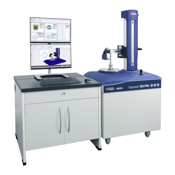
- Page 1 OPER ATOR GUIDE TALYROND ® TALYROND ® 500 H 500 HS 500 PRO 500 T 595 UHPR www.taylor-hobson.com © Taylor Hobson Ltd. 2023.
- Page 2 500 PRO TALYROND ® Introductory operator guide This is Taylor Hobson’s introductory operator guide for the Talyrond 500 PRO instrument range. ® All the specifications in this document are correct at time of production and are subject to change. Please contact Taylor Hobson for further information. Instruments covered: Talyrond 565H PRO...
-
Page 3: Table Of Contents
Contents Introduction ................. 4 Start up procedure ..............4 Metrology 4.0 software ............. 6 User interface .......................7 Selecting the stylus ..................19 Calibration ..................21 Calibrate to scale and crutch angle ............21 Flick standard .....................22 Slip blocks ......................24 Ball calibration (for contour measurement) ........26 3-line standard ....................28 Calibration procedure (Ball) - good and bad results ....31 Calibration artefacts ..................32... -
Page 4: Introduction
Introduction The Talyrond 500 PRO is a range of fully automated roundness/ ® cylindricity instruments that are unsurpassed in accuracy and reliability. The instruments has been designed for stability and accuracy and consists of a frictionless air bearing spindle mounted within a cast iron base and a precision machined column. - Page 5 5. Load Metrology 4.0 software by double-clicking on the shortcut icon located on the PC desktop - DO NOT log on at this point. 6. Press the power button located next to the joystick. 7. Enter login details and click ‘Logon’ to load Metrology 4.0. Then follow the on-screen instructions.
-
Page 6: Metrology 4.0 Software
Metrology 4.0 software Metrology 4.0 incorporates all features that are crucial for measurement and analysis. The software has the added ability of having its own fully automated 3D instrument view which allows a true visualisation of the measurement platform. The software platform is split up into 3 distinct sections: Instrument, Analysis and Production Interface. -
Page 7: User Interface
User interface Instrument ribbon Vertical attitude - Horizontal attitude - set attitude and contact set attitude, contact direction direction and orientation Contact - move stylus Part configurator into contact with part Part Co-ordinate System Clear all PCS (PCS) Instrument control - all instrument axes and Calibration stages... - Page 8 Attitude and orientation • Horizontal Attitude - The Horizontal Attitude icon can be found under the instrument tab in the Positioning section. To move the stylus horizontally, press the “Horizontal Attitude” button and select the orientation. Click the Horizontal Attitude icon and the following window will open.
- Page 9 Instrument control - move types Moving the axes to arrive at different positons around the measurement platform can be done with the use of the ‘Control’ option. ‘Move to position’, ‘Move by distance’ and ‘Continuous move’ options are available to be selected from the control window. The instrument control dialog box can be displayed by selecting the Control icon in the Positioning section of the Instrument tab.
- Page 10 Rotary - Rotate anti- Rotary - Rotate clockwise continuously clockwise continuously move to ove by Rotary - Rotary - m position distance Stop Stop with brake Instrument control - secondary stages • Vacuum chuck - The vacuum chuck mounts on top of the spindle.
- Page 11 Instrument control - inputs • Speed - The speeds for each axes can be set independently. Look through the drop-down list for available speeds or type in a value (as long as it is within the minimum and maximum limits of the system). The units for the value are shown to the right of the box.
- Page 12 TV view and measurement chart Both the TV view and measurement chart show the measurement in real time through the on-screen profile. This is most beneficial if any dirt, marks or obscurities are seen, as the measurement can be stopped at any point, without any loss of data.
- Page 13 Save as Verify program Program properties Run program Run program Pause program continuously Run program ‘n’ times Step through program Run program from step Stop program Record program Tortoise mode 1. New - To start a new program, click the ‘New’ icon. A blank program tab will appear each time the ‘New’...
- Page 14 6. Save/Save as - Save the program by clicking the ‘Save as’ icon. A Windows explorer menu will appear where a location to save the file can be defined. Once the program has been saved once, the ‘Save’ icon can then be clicked save the program.
- Page 15 Measurement toolbar The measurement toolbar is used for all types of measurement. The available measurements will vary depending on the configured instrument. Roundness measurement Flatness measurement 2D Z-axis measurement 2D X-axis measurement 2D Z Auto 2D X Auto measurement measurement Crest measurement Radial crest analysis Crest analysis using...
- Page 16 Configuration ribbon Lock/Unlock Log out Change password User admin User roles Instrument configuration Corrections Configure licence Select language Service report...
- Page 17 Instrument configuration menu Instrument/system Configure the system’s configurator device performances Add, edit or remove Add or remove stylus calibration artefacts Configure axis park Configure the upper and settings lower system end stops Set and calibrate axis Set and calibrate axis reference positions reference positions Set axis datum...
- Page 18 Further icons Stop the current Park instrument instrument operation Exclamation - no Tick - gauge or axes are corrections/calibration calibrated applied Apply saved workspace - Load a workspace from up to 6 layouts available file Save the current Clear workspace and workspace/layout close all windows Save profile...
-
Page 19: Selecting The Stylus
Selecting the stylus To select a stylus, acces the configuration dialog box. 1. Navigate to the ‘Gauge’ section of the instrument ribbon and click on the ‘Settings’ icon. 2. This then brings up a dialog box containing a stylus drop-down list, which is populated with the options available. - Page 20 Note If the selected stylus has previously been calibrated then it is possible to restore that last calibration. Please note it is best-practise metrology to re-calibrate after replacing the stylus to ensure the more accurate results. Adding a new stylus To add a new stylus to Metrology 4.0, access the ‘Gauge’...
-
Page 21: Calibration
Calibration Calibrate to scale and crutch angle 1. Navigate to the ‘Gauge’ section of the instrument ribbon and click on the ‘Calibration to scale’ icon. 2. The calibration dialog box will then be displayed. Complete the relevant options (Explained on Page 30) and click ‘Next’. 3. -
Page 22: Flick Standard
Flick standard The gauge can be calibrated by taking a roundness measurement over a flick standard. The flick standard artefact is defined in the Instrument Configuration (Gauge > Artefacts). Calibration procedure steps are below: 1. Navigate to the ‘Gauge’ section of the instrument ribbon and click on the ‘Calibration’... - Page 23 4. When the calibration routine is complete, the results will appear in the analysis section of Metrology 4.0.
-
Page 24: Slip Blocks
Slip blocks The gauge can be calibrated by taking measurements over a set of slip blocks. The slip blocks artefact is defined in the Instrument Configuration (Gauge > Artefacts). Calibration procedure steps are below: 1. Navigate to the ‘Gauge’ section of the instrument ribbon and click on the ‘Calibration’... - Page 25 4. When the calibration routine is complete, the results will appear in the analysis section of Metrology 4.0.
-
Page 26: Ball Calibration (For Contour Measurement)
Ball calibration (for contour measurement) A calibration is required on the gauge to ensure the acurate motion of the stylus has been corrected. This ensures that the measurement is accurate and reliable. Automated calibration procedure steps are below: 1. Navigate to the ‘Gauge’ section of the instrument ribbon and click on the ‘Calibration’... - Page 27 4. When the calibration routine is complete, the results will appear in the analysis section of Metrology 4.0.
-
Page 28: 3-Line Standard
3-line standard The gauge can be calibrated by taking a measurement over a 3-line standard. The 3-line standard artefact is defined in the Instrument Configuration (Gauge > Artefacts). Calibration procedure steps are below: 1. Navigate to the ‘Gauge’ section of the instrument ribbon and click on the ‘Calibration’... - Page 29 4. When the calibration routine is complete, the results will appear in the analysis section of Metrology 4.0.
- Page 30 1. Gauge range(s) - The desired gauge range over which the calibration is completed can be selected by manually typing the value into this box. Values which have previously been entered can be selected using the drop-down box function. Calibrate to Scale - Select the gauge ranges that are to be calibrated. A separate calibration is stored for each selected range.
-
Page 31: Calibration Procedure (Ball) - Good And Bad Results
Calibration procedure (Ball Calibration only) - good and bad results Illustrations below show the differences between good, bad and acceptqable calibration profiles. Bad calibrations can be caused by dirt on calibration artefacts, damaged styli and/or damaged gauge. 1. Good calibration 2. -
Page 32: Calibration Artefacts
Calibration artefacts Maintenance of calibration artefacts can be conducted by navigating to the ‘Gauge’ section of the ‘Instrument calibration’ menu. There is the option to add, edit or remove a range of different calibration artefacts including: Flick standard Slip blocks Ball standard 3-line standard... - Page 33 Adding a new calibration artefact To add a new calibration artfact in Metrology 4.0, acces the ‘Gauge’ tab in the ‘Instrument Configuration’ section. 1. Select the ‘Calibration artefact’ icon. 2. Click ‘New’, and select the type of calibration artefact required from the list. 3.
-
Page 34: Measurement
Measurement Making a Roundness measurement Roundness measurements are taken by using the spindle to rotate the part. Measurements can be made with the stylus in the X orientation (between 120° and 240° or between 0° and 300°). The measurement procedure steps are below: 1. -
Page 35: Making A 2D Z / 2D X Measurement
Making a 2D Z / 2D X measurement 2D measurements are used to measure single profiles in the Z or X direction.The measurement procedure steps are below: 1. Navigate to the ‘Measurement toolbar’ and click on the ‘2D Z Measurement’ or ‘2D X Measurement’ icon. 2. -
Page 36: Making A Cylinder Map Measurement
Making a Cylinder Map measurement A Cylinder Map measurement is used to measure the surface area of a cylindrical part. A set of vertical measurements are taken around the part and joined together into a surface map.The measurement procedure steps are below: 1. -
Page 37: Making An Ultra High Precision Roundness (Uhpr) Measurement
Making an Ultra High Precision Roundness (UHPR) measurement Ultra High Precision Roundness (UHPR) measurement requires a Talyrond 595 UHPR PRO Roundness ® measurement system using a specially designed rotary stage to achieve roundness accuracies down to ± 5 nm. The measurement procedure steps are below: 1. -
Page 39: Measurement Settings
Measurement settings 1. Measurement name - This is used to distinguish between measurements. The idea is to give the measurement a clear name which can be easily identified later. There is an option to auto-increment from a certain value which can improve the ability to distinguish between measurements and prevent overwrites. - Page 40 Follow mode - Select to allow the X axis to track the surface and keep the gauge within range. Used when measuring parts with large forms, such as cams. 10. Contact before measurement - An automatic contact can be selected before the measurement takes place, this ensures that the correct gauge reading is active before starting.
- Page 41 22. C2 (Rotary Stage) - See descriptions below. Speed / Direction - The speed at which the measurement will take place is set here. The direction at which the measurement will take place. Increment - Rotary stage movement in degrees after each HPR measurement.
- Page 42 T HE ME T R O L O GY E X P E R T S Taylor Hobson UK Taylor Hobson China Tel: +44 (0)116 276 3771 taylor-hobson-china.sales@ametek.com taylor-hobson.sales@ametek.com Shanghai Office Tel: +86 21 5868 5111-110 Taylor Hobson France Beijing Office...
Need help?
Do you have a question about the TAYLOR HOBSON TALYROND 500 PRO and is the answer not in the manual?
Questions and answers