Table of Contents
Advertisement
Quick Links
Transition Networks
SMxxTAT4Xx Web User Guide
SMxxTAT4Xx Family
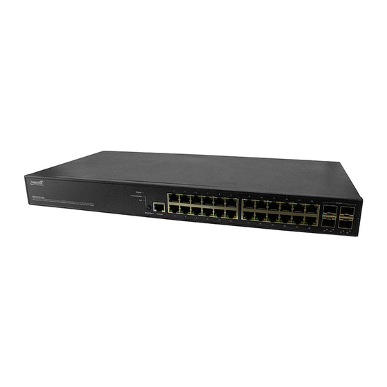
SM48TAT4XA-RP
Managed Gigabit Ethernet PoE+ Switch
(48) 10/100/1000Base-T Ports + (4) 1G/10GBase-X SFP+ Ports
SM24TAT4XB
Managed Gigabit Ethernet PoE+ Switch
(24) 10/100/1000Base-T Ports + (4) 1G/10GBase-X SFP+ Ports
Web User Guide
33786 Rev. A
33786 Rev. A
https://www.transition.com
Page 1 of 340
Advertisement
Table of Contents
Troubleshooting

Related Manuals for Transition Networks SM TAT4X Series


Summary of Contents for Transition Networks SM TAT4X Series
- Page 1 Transition Networks SMxxTAT4Xx Web User Guide SMxxTAT4Xx Family SM48TAT4XA-RP Managed Gigabit Ethernet PoE+ Switch (48) 10/100/1000Base-T Ports + (4) 1G/10GBase-X SFP+ Ports SM24TAT4XB Managed Gigabit Ethernet PoE+ Switch (24) 10/100/1000Base-T Ports + (4) 1G/10GBase-X SFP+ Ports Web User Guide 33786 Rev. A 33786 Rev. A https://www.transition.com Page 1 of 340...
- Page 2 Transition Networks SMxxTAT4Xx Web User Guide Safety Warnings and Cautions These products are not intended for use in life support products where failure of a product could reasonably be expected to result in death or personal injury. Anyone using this product in such an application without express written consent of an officer of Transition Networks does so at their own risk, and agrees to fully indemnify Transition Networks for any damages that may result from such use or sale. Attention: this product, like all electronic products, uses semiconductors that can be damaged by ESD (electrostatic discharge). Always observe appropriate precautions when handling. NOTE: Emphasizes important information or calls your attention to related features or instructions. WARNING: Alerts you to a potential hazard that could cause personal injury. CAUTION: Alerts you to a potential hazard that could cause loss of data, or damage the system or equipment. SMxxTAT4Xx Family (SM48TAT4XA‐RP and SM48TAT4XB) Web User Guide, 33786 Rev. A Record of Revisions Rev Date Description of Changes Initial release of SM48TAT4XA‐RP at FW v8.40.1252, PoE FW v 012‐001, and Bootloader v 1_5‐c480e96r. A 8/6/19 Initial release of SM48TAT4XB at FW v8.40.1252, PoE FW v 208‐211, and HW v1.02. Trademark notice: All trademarks and registered trademarks are the property of their respective owners. All other products or service names used in this publication are for identification purposes only, and may be trademarks or registered trademarks of their respective companies. All other trademarks or registered trademarks mentioned herein are the property of their respective holders. Copyright restrictions: © 2019 Transition Networks, Inc. All rights reserved. No part of this work may be reproduced or used in any form or by any means (graphic, electronic, or mechanical) without written permission from Transition Networks. Address comments on this product or manual to: Transition Networks Inc. 10900 Red Circle Drive, Minnetonka, MN 55343 tel: +1.952.941.7600 | toll free: 1.800.526.9267 | fax: 952.941.2322 ...
-
Page 3: Table Of Contents
Transition Networks SMxxTAT4Xx Web User Guide Contents Safety Warnings and Cautions ........................... 2 Overview ................................ 8 Ordering Information ............................... 8 Related Information .............................. 8 Web User Interface (UI) ............................. 9 Web UI Menu System .............................. 9 Web UI Navigation Tools ............................ 9 Switch > System > System Information ........................10 Switch > System > Power Information ........................12 Switch > System > IP Address > Settings ........................13 Switch > System > IP Address > Advanced Settings ....................15 Switch > System > IP Address > Status ........................19 Switch > System > System Time ..........................20 Switch > System > LLDP > LLDP Configuration .......................23 Switch > System > LLDP > LLDP‐MED Configuration ....................26 Switch > System > LLDP > LLDP Neighbor ......................32 Switch > System > LLDP > LLDP‐MED Neighbor .....................34 Switch > System > LLDP > LLDP Neighbor PoE .......................37 Switch > System > LLDP > LLDP Neighbor EEE .......................38 Switch > System > LLDP > LLDP Statistics .......................40 Switch > System > UPnP ... - Page 4 Transition Networks SMxxTAT4Xx Web User Guide Switch > VLAN Management > Protocol‐based VLAN > Group to VLAN ...............81 Switch > VLAN Management > IP Subnet‐based VLAN ..................82 Switch > VLAN Management > GVRP ........................83 Switch > VLAN Management > Private VLAN ......................85 Switch > VLAN Management > Port Isolation ......................86 Switch > VLAN Management > Voice VLAN > Configuration .................87 Switch > VLAN Management > Voice VLAN > OUI ....................89 Switch > QoS .............................. 90 Switch > QoS > Port Classification ..........................90 Switch > QoS > Port Policers ..........................92 Switch > QoS > Port Shapers ..........................93 Switch > QoS > Storm Control ..........................95 Switch > QoS > Port Schedulers ..........................97 Switch > QoS > Port PCP Remarking ........................98 QoS > DSCP > Port DSCP ............................ 100 QoS > DSCP > DSCP Translation .......................... 101 QoS > DSCP > DSCP Classification ........................ 102 QoS > DSCP > DSCP‐Based QoS ........................... 103 QoS > QoS Control List > Configuration ...................... 104 QoS > QoS Control List > Status .......................... 108 QoS > QoS Control List > Status .......................... 110 QoS > WRED ................................ 111 Spanning Tree > STP Configuration ........................ 113 Spanning Tree > MSTI Configuration ........................ 115 ...
- Page 5 Transition Networks SMxxTAT4Xx Web User Guide DHCP > Relay > Statistics ............................. 161 DHCP > Server > Configuration ........................... 163 DHCP > Server > Status ............................ 164 Security > Management > Account ........................ 165 Security > Management > Privilege Levels ...................... 168 Security > Management > Auth Method ...................... 169 Security > Management > Access Method ...................... 171 Security > Management > HTTPS ........................ 172 Security > 802.1X > Configuration ........................ 174 Security > 802.1X > Configuration ........................ 181 Security > IP Source Guard > Configuration ...................... 182 Security > IP Source Guard > Static Table ...................... 183 Security > IP Source Guard > Dynamic Table ...................... 184 Security > ARP Inspection > Configuration ...................... 185 Security > ARP Inspection > VLAN Configuration .................... 187 Security > ARP Inspection > Static Table ...................... 188 Security > ARP Inspection > Dynamic Table ...................... 189 Security > Port Security > Configuration ...................... 190 Security > Port Security > Configuration ...................... 193 Security > RADIUS > Configuration ........................ 196 ...
- Page 6 Transition Networks SMxxTAT4Xx Web User Guide PTP Clock's Configuration and Status page ..................... 265 PTP Clock's Port Data Set Configuration ...................... 269 PTP > Status ................................. 271 Event Notification > SNMP Trap.......................... 273 Event Notification > eMail .......................... 276 Event Notification > Log > Syslog ........................ 277 Event Notification > Log > View Log ........................ 278 Event Notification > Event Configuration ...................... 279 Diagnostics .............................. 280 Diagnostics > Ping ............................... 280 Diagnostics > Traceroute ............................. 281 Diagnostics > Cable Diagnostics .......................... 282 Diagnostics > Mirroring ............................ 284 Diagnostics > sFlow > Configuration ........................ 286 Diagnostics > sFlow > Statistics ........................... 288 Maintenance .............................. 290 Configuration .............................. 290 Maintenance > Configuration > Save Startup‐config .................. 290 Maintenance > Configuration > Backup ...................... 291 Maintenance > Configuration > Restore ...................... 292 Maintenance > Configuration > Activate ...................... 293 Maintenance > Configuration > Delete ...
- Page 7 Transition Networks SMxxTAT4Xx Web User Guide Contact Us .............................. 334 Warranty ............................... 334 Appendix A – DHCP Per Port Configuration .................... 336 33786 Rev. A https://www.transition.com Page 7 of 340...
-
Page 8: Overview
Transition Networks SMxxTAT4Xx Web User Guide Overview The SMxxTAT4Xx L2+ managed GbE PoE+ switches are next‐generation Ethernet switches offering a full suite of L2 features, additional 10GbE uplink connections, better PoE functionality and usability, including advanced L3 features such as Static Route. In addition to the extensive management features, the SMxxTAT4Xx also provide carrier Ethernet features such as ERPS/EPS/PTPv2, of which make them suitable for Carrier Ethernet applications. The SMxxTAT4Xx deliver 24 or 48 (10M/100M/1G) RJ45 with 48 PoE+ (support 802.3at/af, and total up to 740W) ports, 4 10GbE SFP+ ports and RJ45 Console port. The SMxxTAT4Xx provides high hardware performance and environment flexibility for SMBs and enterprises. The SM48TAT4XA‐RP supports redundant power with a secondary power supply installed. The embedded Device Management System (DMS) features provide the benefits of easy to use, configure, install, and troubleshoot in video surveillance, wireless access, and other SMB and Enterprise applications. The SMxxTAT4Xx is ideal to deliver management simplicity, better user experience, and lowest total cost of ownership. Ordering Information Model Description 48‐port Gigabit PoE+ with (4) 1G/10G SFP+, 820 Watts PoE budget. Supports redundant SM48TAT4XA‐RP power with secondary power supply installed. SM24TAT4XB 24‐port Gigabit PoE+ with (4) 1G/10G SFP+, 370 Watts PoE budget. Secondary power supply for redundant power support (920 Watts). Optional; sold PS‐AC‐920 separately. SFPs See Transition Networks SFP webpage (option; order separately) Related Information A printed Quick Start Guide is shipped with each switch. For Transition Networks Drivers, Firmware, etc. go to the Product Support webpage (logon required). For Transition Networks Manuals, Brochures, Data Sheets, etc. go to the Support Library (no logon required). For SFP manuals see Transition Networks SFP webpage. Related manuals are listed below. ... -
Page 9: Web User Interface (Ui)
Transition Networks SMxxTAT4Xx Web User Guide Web User Interface (UI) This section describes the web user interface of the SM48TAT4XA‐RP and the SM24TAT4XB. The models are very similar except for port count and power supply differences, which are indicated where they occur. Web UI Menu System The left‐hand menu contains two tabs: Switch and DMS. Each tab has sub‐tabs, and many of the sub‐tabs have another level of sub‐tabs. The switch startup menu is shown right: Web UI Navigation Tools : Hide/Display the left pane menus. : Switch icon:: Click on a port to display its status. Click on the Transition Networks logo to display the startup page (the menu path of Switch > System > System Information). : Save changes on this page to the startup‐config file. Help: to be provided. Log out: click to log out of the Web UI. The Login page displays again. : Menu path for the currently‐displayed page. 33786 Rev. A https://www.transition.com Page 9 of 340... -
Page 10: Switch > System > System Information
Transition Networks SMxxTAT4Xx Web User Guide Switch > System > System Information The switch system information is provided here. This page displays at initial startup and after a reboot. The Location and Contact fields are configurable; the remaining fields are read only. Parameter descriptions: Model Name: Displays the factory defined model name for identification purpose (e.g., SM48TAT4XA‐RP or SM24TAT4XB). System Description: Displays the system description (e.g., Managed PoE+ Switch, 48‐port 10/100/1000Base‐T PoE Plus + (4) 1G/10G SFP+ slots). Location: Enter a location description for this switch. Contact: Enter contact information for this switch. System Name: Displays the system name for this switch (e.g., SM48TAT4XA‐RP or SM24TAT4XB). System Date: The current (GMT) system time and date. The system time is obtained from the Timing server running on the switch, if any. The default is 2016‐01‐03T21:13:11+00:00. System Uptime: The period of time the device has been operational in the format 2d 21:38:21. 33786 Rev. A https://www.transition.com Page 10 of 340... - Page 11 Transition Networks SMxxTAT4Xx Web User Guide Bootloader Version: Displays the current boot loader version number (e.g., 1_5‐c480e96). Firmware Version: Displays the current firmware version number and date (e.g., v8.40.1252 2019‐07‐13). PoE Firmware Version: The version of PoE MCU firmware (e.g., 012‐001). Hardware Version: Displays the hardware version of the device (e.g., v1.02). Mechanical Version: Displays the mechanical version of the device (e.g., v1.01). Serial Number: Displays the unique serial number that assigned to the device (e.g., A156119BR1900001). MAC Address: The MAC Address of this switch in the format d0‐c0‐f2‐49‐3b‐1e. Fan Speed: Displays the information about fan speed [rpm] (e.g., 3805(rpm)/3773(rpm)). Temperature 1: Displays the temperature 1 of the system (e.g., 36(C)). Temperature 2: Displays the temperature 2 of the system (e.g., 35(C)). CPU Load (100ms, 1s, 10s): Displays the cpu loading (100ms, 1s, 10s) of the system (e.g., 0%, 4%, 10%). Buttons Auto‐refresh: Check this box to refresh the page automatically every 3 seconds. Refresh: Click to refresh the page immediately. Apply: Click to save changes. Reset: Click to undo any changes made locally and revert to previously saved values. 33786 Rev. A https://www.transition.com Page 11 of 340...
-
Page 12: Switch > System > Power Information
Transition Networks SMxxTAT4Xx Web User Guide Switch > System > Power Information The switch power information is provided here (SM48TAT4XA‐RP only). Parameter descriptions: Detected PSU: Displays SPSU‐820 if the power supply unit present, otherwise displays None. Power Good: Displays the status of power supply unit (Good or Fail). FAN Speed (RPM): The fan speed of power supply unit. Temperature (Degree C): The temperature of power supply unit. Operating Mode: At the dropdown select the operating mode of power supply unit: Redundant: Only provide Primary Power Supply up to 820W when two power supply modules are installed. If one power supply crashes, it can still provide enough power for system operation and also PD’s operation. This is the default. Boost: Provide Primary Power Supply up to 1640W when two power supply modules are installed. When the application total PDs’ power use is over 820W, if one power supply crashes, system will be automatically rebooted due to power loading influence. After the switch finishes rebooting, it will only provide 820W to PDs. Buttons Apply: Click to save changes. Reset: Click to undo any changes made locally and revert to previously saved values. Refresh: Click to refresh the page immediately. Auto‐refresh: Check to refresh the page automatically every 3 seconds. 33786 Rev. A https://www.transition.com Page 12 of 340... -
Page 13: Switch > System > Ip Address > Settings
Transition Networks SMxxTAT4Xx Web User Guide Switch > System > IP Address > Settings This page lets you configure IP basic settings, control IP interfaces, and IP routes. Parameter descriptions: IPv4 DHCP Client Enable: Enable the DHCPv4 client by checking this box. If this option is enabled, the system will configure the IPv4 address and mask of the interface using the DHCPv4 protocol. The DHCPv4 client will announce the configured System Name as hostname to provide DNS lookup. IPv4 Address: The IPv4 address of the interface in dotted decimal notation. If DHCP is enabled, this field configures the fallback address. The field may be left blank if IPv4 operation on the interface is not desired ‐ or no DHCP fallback address is desired. The default is 192.168.1.77. Subnet Mask: The IPv4 network mask, in number of bits (prefix length). Valid values are 0 ‐ 30 bits for an IPv4 address. If DHCP is enabled, this field configures the fallback address network mask. The field may be left blank if IPv4 operation on the interface is not desired, or, if no DHCP fallback address is desired. The default is 255.255.255.0. Gateway: The IP address of the IP gateway. Valid format is dotted decimal notation or a valid IPv6 notation. Gateway and Network must be of the same type. The default is 192.168.1.254. DNS Server: This setting controls the DNS name resolution done by the switch. There are four servers available for configuration, and the index of the server presents the preference (less index has higher priority) in doing DNS name resolution. These modes are supported: No DNS server: No DNS server will be used (the default). Configured IPv4: Explicitly provide the valid IPv4 unicast address of the DNS Server in dotted decimal notation. Make sure the configured DNS server is reachable (e.g. via Ping) for activating DNS service. Configured IPv6: Explicitly provide the valid IPv6 unicast (except linklocal) address of the DNS Server. Make sure the configured DNS server can be reached (e.g. via Ping6) for activating DNS service. From any DHCPv4 interfaces: The first DNS server offered from a DHCPv4 lease to a DHCPv4‐enabled interface will be used. 33786 Rev. A https://www.transition.com Page 13 of 340... - Page 14 Transition Networks SMxxTAT4Xx Web User Guide From this DHCPv4 interface: Specify from which DHCPv4‐enabled interface a provided DNS server should be preferred. From any DHCPv6 interfaces: The first DNS server offered from a DHCPv6 lease to a DHCPv6‐enabled interface will be used. From this DHCPv6 interface: Specify from which DHCPv6‐enabled interface a provided DNS server should be preferred. Buttons Apply: Click to save changes. 33786 Rev. A https://www.transition.com Page 14 of 340...
-
Page 15: Switch > System > Ip Address > Advanced Settings
Transition Networks SMxxTAT4Xx Web User Guide Switch > System > IP Address > Advanced Settings This page lets you configure IP basic settings and set IP interfaces and IP routes. The maximum number of interfaces supported is 128 and the maximum number of routes is 128. Parameter descriptions: Basic Settings Mode: Configure whether the IP stack should act as a Host or a Router. In Host mode, IP traffic between interfaces will not be routed. In Router mode traffic is routed between all interfaces. DNS Server: This setting controls the DNS name resolution done by the switch. There are four servers available for configuration, and the index of the server presents the preference (less index has higher priority) in doing DNS name resolution. These modes are supported: No DNS server: No DNS server will be used. Configured IPv4: Explicitly provide the valid IPv4 unicast address of the DNS Server in dotted decimal notation. Make sure the configured DNS server could be reachable (e.g. via PING) for activating DNS service. Configured IPv6: Explicitly provide the valid IPv6 unicast (except linklocal) address of the DNS Server. Make sure the configured DNS server could be reachable (e.g. via PING6) for activating DNS service. From any DHCPv4 interfaces: The first DNS server offered from a DHCPv4 lease to a DHCPv4‐enabled interface will be used. 33786 Rev. A https://www.transition.com Page 15 of 340... - Page 16 Transition Networks SMxxTAT4Xx Web User Guide From this DHCPv4 interface: Specify from which DHCPv4‐enabled interface a provided DNS server should be preferred. From any DHCPv6 interfaces: The first DNS server offered from a DHCPv6 lease to a DHCPv6‐enabled interface will be used. From this DHCPv6 interface: Specify from which DHCPv6‐enabled interface a provided DNS server should be preferred. DNS Proxy: When DNS proxy is enabled, system will relay DNS requests to the currently configured DNS server, and reply as a DNS resolver to the client devices on the network. Note: Only IPv4 DNS proxy is currently supported. IP Interfaces DHCP Per Port Mode: Enable/Disable DHCP per port. DHCP Per Port IP: Define the IP range for DHCP per port. The DHCP Per Port IP range must equal the switch TP port number (24 for the SM24TAT4XB or 48 for the SM48TAT4XA‐RP). Delete: Select this option to delete an existing IP interface. VLAN: The VLAN associated with the IP interface. Only ports in this VLAN will be able to access the IP interface. This field is only available for input when creating a new interface. IPv4 DHCP Enabled: Enable the DHCPv4 client by checking this box. If this option is enabled, the system will configure the IPv4 address and mask of the interface using the DHCPv4 protocol. IPv4 DHCP Clinet Identifier Type: The DHCP Client identifier per IETF RFC 4361. IPv4 DHCP Clinet Identifier IfMac: The interface name of DHCP client identifier. When DHCPv4 client is enabled and the client identifier type is 'ifmac', the configured interface's hardware MAC address will be used in the DHCP option 61 field. IPv4 DHCP Clinet Identifier ASCII: The ASCII string of DHCP client identifier. When DHCPv4 client is enabled and the client identifier type is 'ascii', the ASCII string will be used in the DHCP option 61 field. IPv4 DHCP Clinet Identifier HEX: The hexadecimal string of DHCP client identifier. When DHCPv4 client is enabled and the client identifier type 'hex', the hexadecimal value will be used in the DHCP option 61 field. IPv4 DHCP Hostname: The hostname of DHCP client. If DHCPv4 client is enabled, the configured hostname will be used in the DHCP option 12 field. When this value is empty string, the field uses the configured system name plus the latest three bytes of system MAC addresses as the hostname. IPv4 DHCP Fallback Timeout: The number of seconds for trying to obtain a DHCP lease. After this period expires, a configured IPv4 address will be used as IPv4 interface address. A value of zero disables the fallback mechanism, such that DHCP will keep retrying until a valid lease is obtained. Legal values are 0 to 4294967295 seconds. IPv4 DHCP Current Lease: For DHCP interfaces with an active lease, this column show the current interface address, as provided by the DHCP server. IPv4 Address: The IPv4 address of the interface in dotted decimal notation. If DHCP is enabled, this field configures the fallback address. The field may be left blank if IPv4 operation on the interface is not desired ‐ or no ...
- Page 17 Transition Networks SMxxTAT4Xx Web User Guide DHCPv6 Enable: Enable the DHCPv6 client by checking this box. If this option is enabled, the system will configure the IPv6 address of the interface using the DHCPv6 protocol. DHCPv6 Rapid Commit: Enable the DHCPv6 Rapid‐Commit option by checking this box. If this option is enabled, the DHCPv6 client terminates the waiting process as soon as a Reply message with a Rapid Commit option is received. This option is only manageable when DHCPv6 client is enabled. DHCPv6 Current Lease: For DHCPv6 interface with an active lease, this column shows the interface address provided by the DHCPv6 server. IPv6 Address: The IPv6 address of the interface. An IPv6 address is in 128‐bit records represented as eight fields of up to four hexadecimal digits with a colon separating each field (:). For example, fe80::215:c5ff:fe03:4dc7. The symbol :: is a special syntax that can be used as a shorthand way of representing multiple 16‐bit groups of contiguous zeros; but it can appear only once. The system accepts the valid IPv6 unicast address only, except IPv4‐Compatible address and IPv4‐Mapped address. This field may be left blank if IPv6 operation on the interface is not desired. IPv6 Mask: The IPv6 network mask, in number of bits (prefix length). Valid values are 1 ‐ 128 bits for an IPv6 address. This field may be left blank if IPv6 operation on the interface is not desired. Resolving IPv6 DAD: The link‐local address is formed from an interface identifier based on the hardware address which is supposed to be uniquely assigned. Once the DAD (Duplicate Address Detection) detects the address duplication, the operation on the interface SHOULD be disabled. Currently, manual intervention is required to resolve the address duplication. For example, check whether the loop occurs in the VLAN or there is indeed other device occupying the same hardware address as the device in the VLAN. After making sure the specific link‐local address is unique on the IPv6 link in use, delete and then add the specific IPv6 interface to restart the IPv6 operations on this interface. Link‐Local Address binding interface: Configure Link‐Local IP address to a different VLAN interface. The first IP interface entry is the default value. IP Routes Delete: Select this option to delete an existing IP route. Network: The destination IP network or host address of this route. Valid format is dotted decimal notation or a valid IPv6 notation. A default route can use the value 0.0.0.0or IPv6 :: notation. Mask Length: The destination IP network or host mask, in number of bits (prefix length). It defines how much of a network address that must match, in order to qualify for this route. Valid values are 0 ‐ 32 bits respectively 128 for IPv6 routes. Only a default route will have a mask length of 0 (as it will match anything). Gateway: The IP address of the IP gateway. Valid format is dotted decimal notation or a valid IPv6 notation. Gateway and Network must be of the same type. Distance (Only for IPv4): The distance value of route entry is used to provide the priority information of the routing protocols to routers. When there are two or more different routing protocols are involved and have the same destination, the distance value can be used to select the best path. ...
- Page 18 Transition Networks SMxxTAT4Xx Web User Guide Add Interface: Click to add a new IP interface. A maximum of 128 interfaces is supported. Add Route: Click to add a new IP route. A maximum of 128 routes is supported. Apply: Click to save changes. When the message “Update success!” displays, click OK to clear the message. Reset: Click to undo any changes made locally and revert to previously saved values. Messages : DHCP Per Port IP range (192.168.1.1 ‐ 192.168.1.30) is not equal to switch TP port number (24) DHCP Per Port IP range (192.168.1.1 ‐ 192.168.1.52) is not equal to switch TP port number (48) No any valid network address/netmask input. Please enable DHCP or give a valid IPv4 or IPv6 network address and netmask 33786 Rev. A https://www.transition.com Page 18 of 340...
-
Page 19: Switch > System > Ip Address > Status
Transition Networks SMxxTAT4Xx Web User Guide Switch > System > IP Address > Status This page displays the status of the IP protocol layer. The status displayed includes IP interfaces, IP routes and neighbour cache (ARP cache) status. Parameter descriptions: IP Interfaces Interface: The name of the interface. Type: The address type of the entry. This may be LINK or IPv4. Address: The current address of the interface (of the given type). Status: The status flags of the interface (and/or address). IP Routes Network: The destination IP network or host address of this route. Gateway: The gateway address of this route. Status: The status flags of the route. Neighbour cache IP Address: The IP address of the entry. Link Address: The Link (MAC) address for which a binding to the IP address given exist. Buttons Auto‐refresh: Check this box to refresh the page automatically every 3 seconds. Refresh: Click to refresh the page immediately. 33786 Rev. A https://www.transition.com Page 19 of 340... -
Page 20: Switch > System > System Time
Transition Networks SMxxTAT4Xx Web User Guide Switch > System > System Time This page lets you configure clock time, time zone, and Daylight Saving Time parameters. Parameter descriptions: Time Configuration Clock Source: There are two modes for configuring how the Clock Source from. Select "Use Local Settings" for Clock Source from Local Time. Select "Use NTP Server" for Clock Source from an NTP Server. System Date: Show the current date and time of the system in the format yyyy‐mm‐dd hh:mm:ss. The year of system date (yyyy) can be 2011 ‐ 2037. 33786 Rev. A https://www.transition.com Page 20 of 340... - Page 21 Transition Networks SMxxTAT4Xx Web User Guide Time Zone Configuration Time Zone: Lists various Time Zones worldwide. Select appropriate Time Zone from the drop down and click Apply to set. Acronym: User can set the acronym of the time zone. This is a User configurable acronym to identify the time zone (up to 16 characters ). Daylight Saving Time Configuration Daylight Saving Time: This is used to set the clock forward or backward according to the configurations set below for a defined Daylight Saving Time duration. Select 'Disable' to disable the Daylight Saving Time configuration. Select 'Recurring' and configure the Daylight Saving Time duration to repeat the configuration every year. Select 'Non‐Recurring' and configure the Daylight Saving Time duration for single time configuration. The default is Disabled ) Recurring Configurations Start time settings Week ‐ Select the starting week number. Day ‐ Select the starting day. Month ‐ Select the starting month. Hours ‐ Select the starting hour. Minutes ‐ Select the starting minute. End time settings Week ‐ Select the ending week number. Day ‐ Select the ending day. Month ‐ Select the ending month. Hours ‐ Select the ending hour. Minutes ‐ Select the ending minute. Offset settings Offset ‐ Enter the number of minutes to add during Daylight Saving Time (1 ‐ 1440 minutes). Non Recurring Configurations Start time settings Month ‐ Select the starting month. Date ‐ Select the starting date. Year ‐ Select the starting year. Hours ‐ Select the starting hour. Minutes ‐ Select the starting minute. End time settings ...
- Page 22 Transition Networks SMxxTAT4Xx Web User Guide Offset settings Offset ‐ Enter the number of minutes to add during Daylight Saving Time (1 ‐ 1440 minutes) Buttons Apply: Click to save changes. Reset: Click to undo any changes made locally and revert to previously saved values. Configure NTP Server: Click the button to display the NTP Configuration page as shown and described below. NTP Configuration page Parameter descriptions: NTP Time‐Sync Interval: The switch is periodically transmitting NTP frames to its servers for having the network time information up‐to‐date. The interval between each NTP frame is determined by the NTP Time‐Sync Interval value. Valid values are 5, 10, 15, 30, 60, or 120 minutes. Server #: Provide the IPv4 or IPv6 address of a NTP server. IPv6 address is in 128‐bit records represented as eight fields of up to four hexadecimal digits with a colon separating each field (:). For example, 'fe80::215:c5ff:fe03:4dc7'. The symbol '::' is a special syntax that can be used as a shorthand way of representing multiple 16‐bit groups of contiguous zeros; but it can appear only once. It can also represent a legally valid IPv4 address. For example, '::192.1.2.34'. In addition, it can also accept a domain name address. Buttons Apply: Click to save changes. Reset: Click to undo any changes made locally and revert to previously saved values. 33786 Rev. A https://www.transition.com Page 22 of 340...
-
Page 23: Switch > System > Lldp > Lldp Configuration
Transition Networks SMxxTAT4Xx Web User Guide Switch > System > LLDP > LLDP Configuration This page lets you view and configure the current LLDP interface parameters. The Link Layer Discovery Protocol (LLDP) is an IEEE 802.1ab standard protocol. The protocol specified allows stations attached to an IEEE 802 LAN to advertise, to other stations attached to the same IEEE 802 LAN, the major capabilities provided by the system incorporating that station, the management address or addresses of the entity or entities that provide management of those capabilities, and the identification of the stations point of attachment to the IEEE 802 LAN required by those management entity or entities. The information distributed via this protocol is stored by its recipients in a standard Management Information Base (MIB), making it possible for the information to be accessed by a Network Management System (NMS) using a management protocol such as the Simple Network Management Protocol (SNMP). Parameter descriptions: LLDP Parameters Tx Interval: The switch periodically transmits LLDP frames to its neighbors for having the network discovery information up‐to‐date. The interval between each LLDP frame is determined by the Tx Interval value. Valid values are 5 ‐ 32768 seconds. Tx Hold: Each LLDP frame contains information about how long time the information in the LLDP frame will be considered valid. The LLDP information valid period is set to Tx Hold multiplied by Tx Interval seconds. Valid values are 2 ‐ 10 times. 33786 Rev. A https://www.transition.com Page 23 of 340... - Page 24 Transition Networks SMxxTAT4Xx Web User Guide Tx Delay: If some configuration is changed (e.g. the IP address) a new LLDP frame is transmitted, but the time between the LLDP frames will always be at least the value of Tx Delay seconds. Tx Delay cannot be larger than 1/4 of the Tx Interval value. Valid values are restricted to 1 ‐ 8192 seconds. Tx Reinit: When an interface is disabled, LLDP is disabled or the switch is rebooted, a LLDP shutdown frame is transmitted to the neighboring units, signaling that the LLDP information isn't valid anymore. Tx Reinit controls the amount of seconds between the shutdown frame and a new LLDP initialization. Valid values are restricted to 1 ‐ 10 seconds. LLDP Port Configuration Port: The switch port of the logical LLDP interface. Mode: Select the LLDP mode: Rx only: The switch will not send out LLDP information, but LLDP information from neighbor units is analyzed. Tx only: The switch will drop LLDP information received from neighbors, but will send out LLDP information. Disabled: The switch will not send out LLDP information, and will drop LLDP information received from neighbors. Enabled: The switch will send out LLDP information, and will analyze LLDP information received from neighbors. CDP aware: Select Cisco Discovery Protocol awareness. The CDP operation is restricted to decoding incoming CDP frames (The switch doesn't transmit CDP frames). CDP frames are only decoded if LLDP on the interface is enabled. Only CDP TLVs that can be mapped to a corresponding field in the LLDP neighbors' table are decoded. All other TLVs are discarded (Unrecognized CDP TLVs and discarded CDP frames are not shown in the LLDP statistics.). CDP TLVs are mapped onto LLDP neighbors' table as shown below. CDP TLV "Device ID" is mapped to the LLDP "Chassis ID" field. CDP TLV "Address" is mapped to the LLDP "Management Address" field. The CDP address TLV can contain multiple addresses, but only the first address is shown in the LLDP neighbors table. CDP TLV "Port ID" is mapped to the LLDP "Port ID" field. CDP TLV "Version and Platform" is mapped to the LLDP "System Description" field. Both the CDP and LLDP support "system capabilities", but the CDP capabilities cover capabilities that are not part of the LLDP. These capabilities are shown as "others" in the LLDP neighbors' table. If all interfaces have CDP awareness disabled the switch forwards CDP frames received from neighbor devices. If at least one interface has CDP awareness enabled all CDP frames are terminated by the switch. ...
- Page 25 Transition Networks SMxxTAT4Xx Web User Guide Buttons Apply: Click to save changes. Reset: Click to undo any changes made locally and revert to previously saved values. 33786 Rev. A https://www.transition.com Page 25 of 340...
-
Page 26: Switch > System > Lldp > Lldp-Med Configuration
Transition Networks SMxxTAT4Xx Web User Guide Switch > System > LLDP > LLDP‐MED Configuration This page lets you configure the LLDP‐MED. This function applies to VoIP devices which support LLDP‐MED. Parameter descriptions: Fast start repeat count Fast start repeat count: Rapid startup and Emergency Call Service Location Identification Discovery of endpoints is a critically important aspect of VoIP systems in general. In addition, it is best to advertise only those pieces of information which are specifically relevant to particular endpoint types (for example only advertise the voice network policy to permitted voice‐capable devices), both in order to conserve the limited LLDPU space and to reduce security and system integrity issues that can come with inappropriate knowledge of the network policy. With this in mind LLDP‐MED defines an LLDP‐MED Fast Start interaction between the protocol and the application layers on top of the protocol, in order to achieve these related properties. Initially, a Network Connectivity Device will only transmit LLDP TLVs in an LLDPDU. Only after an LLDP‐MED Endpoint Device is detected, will an LLDP‐MED capable Network Connectivity Device start to advertise LLDP‐MED TLVs in outgoing LLDPDUs on the 33786 Rev. A https://www.transition.com Page 26 of 340... - Page 27 Transition Networks SMxxTAT4Xx Web User Guide associated interface. The LLDP‐MED application will temporarily speed up the transmission of the LLDPDU to start within a second, when a new LLDP‐MED neighbor has been detected in order share LLDP‐MED information as fast as possible to new neighbors. Because there is a risk of an LLDP frame being lost during transmission between neighbors, it is recommended to repeat the fast start transmission multiple times to increase the possibility of the neighbors receiving the LLDP frame. With Fast start repeat count it is possible to specify the number of times the fast start transmission would be repeated. The recommended value is 4 times, given that 4 LLDP frames with a 1 second interval will be transmitted, when an LLDP frame with new information is received. Note that LLDP‐MED and the LLDP‐MED Fast Start mechanism is only intended to run on links between LLDP‐MED Network Connectivity Devices and Endpoint Devices, and as such does not apply to links between LAN infrastructure elements, including Network Connectivity Devices, or other types of links. Transmit TLVs: It is possible to select which LLDP‐MED information that shall be transmitted to the neighbors. When the checkbox is checked the information is included in the frame transmitted to the neighbor. Port: The interface name to which the configuration applies. Transmit TLVs – Capabilities: When checked the switch's capabilities is included in LLDP‐MED information transmitted. Transmit TLVs – Policies: When checked the configured policies for the interface is included in LLDP‐MED information transmitted. Transmit TLVs – Location: When checked the configured location information for the switch is included in LLDP‐MED information transmitted. Transmit TLVs – PoE: When checked the configured PoE (Power Over Ethernet) information for the interface is included in LLDP‐MED information transmitted. Device Type: Any LLDP‐MED Device is operating as a specific type of LLDP‐MED Device, which may be either a Network Connectivity Device or a specific Class of Endpoint Device, as defined below. A Network Connectivity Device is a LLDP‐MED Device that provides access to the IEEE 802 based LAN infrastructure for LLDP‐MED Endpoint Devices An LLDP‐MED Network Connectivity Device is a LAN access device based on any of the following technologies : 1. LAN Switch/Router 2. IEEE 802.1 Bridge 3. IEEE 802.3 Repeater (included for historical reasons) 4. IEEE 802.11 Wireless Access Point 5. Any device that supports the IEEE 802.1AB and MED extensions that can relay IEEE 802 frames via any method. An Endpoint Device is an LLDP‐MED Device that sits at the network edge and provides some aspect of IP communications service, based on IEEE 802 LAN technology. The main difference between a Network Connectivity Device and an Endpoint Device is that only an Endpoint Device can start the LLDP‐MED information exchange. Even though a switch always should be a Network Connectivity Device, it is possible to configure it to act as an ...
- Page 28 Transition Networks SMxxTAT4Xx Web User Guide Coordinates Location Latitude: Latitude SHOULD be normalized to within 0‐90 degrees with a maximum of 4 digits. It is possible to specify the direction to either North of the equator or South of the equator. Longitude: Longitude SHOULD be normalized to within 0‐180 degrees with a maximum of 4 digits. It is possible to specify the direction to either East of the prime meridian or West of the prime meridian. Altitude: Altitude SHOULD be normalized to within ‐2097151.9 to 2097151.9 with a maximum of 1 digit. It is possible to select between two altitude types (floors or meters): Meters: Representing meters of Altitude defined by the vertical datum specified. Floors: Representing altitude in a form more relevant in buildings which have different floor‐to‐floor dimensions. An altitude = 0.0 is meaningful even outside a building, and represents ground level at the given latitude and longitude. Inside a building, 0.0 represents the floor level associated with ground level at the main entrance. Map Datum: The Map Datum is used for the coordinates given in these options: WGS84: (Geographical 3D) ‐ World Geodesic System 1984, CRS Code 4327, Prime Meridian Name: Greenwich. NAD83/NAVD88: North American Datum 1983, CRS Code 4269, Prime Meridian Name: Greenwich; The associated vertical datum is the North American Vertical Datum of 1988 (NAVD88). This datum pair is to be used when referencing locations on land, not near tidal water (which would use Datum = NAD83/MLLW). NAD83/MLLW: North American Datum 1983, CRS Code 4269, Prime Meridian Name: Greenwich; The associated vertical datum is Mean Lower Low Water (MLLW). This datum pair is to be used when referencing locations on water/sea/ocean. Civic Address Location: IETF Geopriv Civic Address based Location Configuration Information (Civic Address LCI). The total number of characters for the combined civic address information must not exceed 250 characters. A couple of notes to the limitation of 250 characters. 1) If more than one civic address location is used, each of the additional civic address locations will use 2 extra characters in addition to the civic address location text. 2) The 2 letter country code is not part of the 250 characters limitation. Country code: The two‐letter ISO 3166 country code in capital ASCII letters ‐ Example: DK, DE or US. State: National subdivisions (state, canton, region, province, prefecture). County: County, parish, gun (Japan), district. City: City, township, shi (Japan) ‐ Example: Copenhagen. City district: City division, borough, city district, ward, chou (Japan). Block (Neighborhood): Neighborhood, block. Street: Street ‐ Example: Poppelvej. Leading street direction: Leading street direction ‐ Example: N. Trailing street suffix: Trailing street suffix ‐ Example: SW. Street suffix: Street suffix ‐ Example: Ave, Platz. ...
- Page 29 Transition Networks SMxxTAT4Xx Web User Guide Landmark: Landmark or vanity address ‐ Example: Columbia University. Additional location info: Additional location info ‐ Example: South Wing. Name: Name (residence and office occupant) ‐ Example: Flemming Jahn. Zip code: Postal/zip code ‐ Example: 2791. Building: Building (structure) ‐ Example: Low Library. Apartment: Unit (Apartment, suite) ‐ Example: Apt 42. Floor: Floor ‐ Example: 4. Room no.: Room number ‐ Example: 450F. Place type: Place type ‐ Example: Office. Postal community name: Postal community name ‐ Example: Leonia. P.O. Box: Post office box (P.O. BOX) ‐ Example: 12345. Additional code: Additional code ‐ Example: 1320300003. Emergency Call Service: Emergency Call Service (e.g. E911 and others), such as defined by TIA or NENA. Emergency Call Service: Emergency Call Service ELIN identifier data format is defined to carry the ELIN identifier as used during emergency call setup to a traditional CAMA or ISDN trunk‐based PSAP. This format consists of a numerical digit string, corresponding to the ELIN to be used for emergency calling. Policies: Network Policy Discovery enables the efficient discovery and diagnosis of mismatch issues with the VLAN configuration, along with the associated Layer 2 and Layer 3 attributes, which apply for a set of specific protocol applications on that port. Improper network policy configurations are a very significant issue in VoIP environments that frequently result in voice quality degradation or loss of service. Policies are only intended for use with applications that have specific 'real‐time' network policy requirements, such as interactive voice and/or video services. The network policy attributes advertised are: 1. Layer 2 VLAN ID (IEEE 802.1Q‐2003) 2. Layer 2 priority value (IEEE 802.1D‐2004) 3. Layer 3 Diffserv code point (DSCP) value (IETF RFC 2474) This network policy is potentially advertised and associated with multiple sets of application types supported on a given port. The application types specifically addressed are: 1. Voice 2. Guest Voice 3. Softphone Voice 4. Video Conferencing 5. Streaming Video 6. Control / Signalling (conditionally support a separate network policy for the media types above) A large network may support multiple VoIP policies across the entire organization, and different policies per application type. LLDP‐MED allows multiple policies to be advertised per port, each corresponding to a different application type. Different ports on the same Network Connectivity Device may advertise different sets of policies, based on the authenticated user identity or port configuration. ...
- Page 30 Transition Networks SMxxTAT4Xx Web User Guide Note that LLDP‐MED is not intended to run on links other than between Network Connectivity Devices and Endpoints, and therefore does not need to advertise the multitude of network policies that frequently run on an aggregated link interior to the LAN. Delete: Check to delete the policy. It will be deleted during the next save. Policy ID: ID for the policy. This is auto generated and shall be used when selecting the policies that shall be mapped to the specific interfaces. Application Type: Intended use of the application types: Voice ‐ for use by dedicated IP Telephony handsets and other similar appliances supporting interactive voice services. These devices are typically deployed on a separate VLAN for ease of deployment and enhanced security by isolation from data applications. Voice Signalling (conditional) ‐ for use in network topologies that require a different policy for the voice signalling than for the voice media. This application type should not be advertised if all the same network policies apply as those advertised in the Voice application policy. Guest Voice ‐ support a separate 'limited feature‐set' voice service for guest users and visitors with their own IP Telephony handsets and other similar appliances supporting interactive voice services. Guest Voice Signalling (conditional) ‐ for use in network topologies that require a different policy for the guest voice signalling than for the guest voice media. This application type should not be advertised if all the same network policies apply as those advertised in the Guest Voice application policy. Softphone Voice ‐ for use by softphone applications on typical data centric devices, such as PCs or laptops. This class of endpoints frequently does not support multiple VLANs, if at all, and are typically configured to use an 'untagged' VLAN or a single 'tagged' data specific VLAN. When a network policy is defined for use with an 'untagged' VLAN (see Tagged flag below), then the L2 priority field is ignored and only the DSCP value has relevance. Video Conferencing ‐ for use by dedicated Video Conferencing equipment and other similar appliances supporting real‐time interactive video/audio services. Streaming Video ‐ for use by broadcast or multicast based video content distribution and other similar applications supporting streaming video services that require specific network policy treatment. Video applications relying on TCP with buffering would not be an intended use of this application type. Video Signalling (conditional) ‐ for use in network topologies that require a separate policy for the video signalling than for the video media. This application type should not be advertised if all the same network policies apply as those advertised in the Video Conferencing application policy. Tag: Tag indicating whether the specified application type is using a 'tagged' or an 'untagged' VLAN. Untagged indicates that the device is using an untagged frame format and as such does not include a tag header as defined by IEEE 802.1Q‐2003. In this case, both the VLAN ID and the Layer 2 priority fields are ignored and only the DSCP value has relevance. Tagged indicates that the device is using the IEEE 802.1Q tagged frame format, and that both the VLAN ID and the Layer 2 priority values are being used, as well as the DSCP value. The tagged format includes an additional field, known as the tag header. The tagged frame format also includes priority tagged ...
- Page 31 Transition Networks SMxxTAT4Xx Web User Guide DSCP: DSCP value to be used to provide Diffserv node behavior for the specified application type as defined in IETF RFC 2474. DSCP may contain one of 64 code point values (0 through 63). A value of 0 represents use of the default DSCP value as defined in RFC 2475. Adding a new policy Click the Add New Policy button to add a new policy. Specify the Application type, Tag, VLAN ID, L2 Priority and DSCP for the new policy. Click "Save". The number of policies supported is 32. Policies Interface Configuration: Every interface may advertise a unique set of network policies or different attributes for the same network policies, based on the authenticated user identity or interface configuration. Interface: The interface name to which the configuration applies. Policy Id: The set of policies that shall apply to a given interface. The set of policies is selected by checking the checkboxes that corresponds to the policies. Buttons Apply: Click to save changes. Reset: Click to undo any changes made locally and revert to previously saved values. 33786 Rev. A https://www.transition.com Page 31 of 340...
-
Page 32: Switch > System > Lldp > Lldp Neighbor
Transition Networks SMxxTAT4Xx Web User Guide Switch > System > LLDP > LLDP Neighbor This page provides a status overview for all LLDP neighbors. The displayed table contains a row for each interface on which an LLDP neighbor is detected. Parameter descriptions: Local Port: The interface on which the LLDP frame was received (e.g., GigabitEthernet 1/5). Chassis ID: The identification of the neighbor's LLDP frames (e.g., AC‐CC‐8E‐AD‐F8‐2A). Port ID: The identification of the neighbor port’s Port # or MAC address. Port Description: the port description advertised by the neighbor device (e.g., eth0). System Name: The name advertised by the neighbor unit. System Capabilities: Describes the neighbor unit's capabilities. The possible capabilities are: 1. Other 2. Repeater 3. Bridge 4. WLAN Access Point 5. Router 6. Telephone 7. DOCSIS cable device 8. Station only 9. Reserved When a capability is enabled, the capability is followed by (+). If the capability is disabled, the capability is followed by (‐). System Description: The model # of the neighbor device. Management Address: The neighbor unit's address that is used for higher layer entities to assist discovery by the network management. This could for instance hold the neighbor's IP address. Click the linked text to connect to the neighbor device (see below). 33786 Rev. A https://www.transition.com Page 32 of 340... - Page 33 Transition Networks SMxxTAT4Xx Web User Guide Buttons Auto‐refresh: Check this box to refresh the page automatically every 3 seconds. Refresh: Click to refresh the page immediately. Linked Neighbor Device Examples 33786 Rev. A https://www.transition.com Page 33 of 340...
-
Page 34: Switch > System > Lldp > Lldp-Med Neighbor
Transition Networks SMxxTAT4Xx Web User Guide Switch > System > LLDP > LLDP‐MED Neighbor This page provides a status overview of all LLDP‐MED neighbors. The displayed table contains a row for each interface on which an LLDP neighbor is detected. This function applies to VoIP devices which support LLDP‐MED. Parameter descriptions: Port: The interface on which the LLDP frame was received. Device Type: LLDP‐MED Devices are comprised of two primary Device Types: Network Connectivity Devices and Endpoint Devices. LLDP‐MED Network Connectivity Device definition: LLDP‐MED Network Connectivity Devices, as defined in TIA‐1057, provide access to the IEEE 802 based LAN infrastructure for LLDP‐MED Endpoint Devices. An LLDP‐MED Network Connectivity Device is a LAN access device based on any of these technologies: 1. LAN Switch/Router 2. IEEE 802.1 Bridge 3. IEEE 802.3 Repeater (included for historical reasons) 4. IEEE 802.11 Wireless Access Point 5. Any device that supports the IEEE 802.1AB and MED extensions defined by TIA‐1057 and can relay IEEE 802 frames via any method. LLDP‐MED Endpoint Device definition: LLDP‐MED Endpoint Devices, as defined in TIA‐1057, are located at the IEEE 802 LAN network edge, and participate in IP communication service using the LLDP‐MED framework. Within the LLDP‐MED Endpoint Device category, the LLDP‐MED scheme is broken into further Endpoint Device Classes, as defined in the following. Each LLDP‐MED Endpoint Device Class is defined to build on the capabilities defined for the previous Endpoint Device Class. For‐example will any LLDP‐MED Endpoint Device claiming compliance as a Media Endpoint (Class II) also support all aspects of TIA‐1057 applicable to Generic Endpoints (Class I), and any LLDP‐MED Endpoint Device claiming compliance as a Communication Device (Class III) will also support all aspects of TIA‐1057 applicable to both Media Endpoints (Class II) and Generic Endpoints (Class I). LLDP‐MED Generic Endpoint (Class I): The LLDP‐MED Generic Endpoint (Class I) definition is applicable to all endpoint products that require the base LLDP discovery services defined in TIA‐1057, however do not support IP media or act as an end‐user communication appliance. Such devices may include (but are not limited to) IP Communication Controllers, other communication related servers, or any device requiring basic services as defined in TIA‐1057. Discovery services defined in this class include LAN configuration, device location, network policy, power management, and inventory management. 33786 Rev. A https://www.transition.com Page 34 of 340... - Page 35 Transition Networks SMxxTAT4Xx Web User Guide LLDP‐MED Media Endpoint (Class II): The LLDP‐MED Media Endpoint (Class II) definition is applicable to all endpoint products that have IP media capabilities however may or may not be associated with a particular end user. Capabilities include all of the capabilities defined for the previous Generic Endpoint Class (Class I), and are extended to include aspects related to media streaming. Example product categories expected to adhere to this class include (but are not limited to) Voice / Media Gateways, Conference Bridges, Media Servers, and similar. Discovery services defined in this class include media‐type‐specific network layer policy discovery. LLDP‐MED Communication Endpoint (Class III): The LLDP‐MED Communication Endpoint (Class III) definition is applicable to all endpoint products that act as end user communication appliances supporting IP media. Capabilities include all of the capabilities defined for the previous Generic Endpoint (Class I) and Media Endpoint (Class II) classes, and are extended to include aspects related to end user devices. Example product categories expected to adhere to this class include (but are not limited to) end user communication appliances, such as IP Phones, PC‐based softphones, or other communication appliances that directly support the end user. Discovery services defined in this class include provision of location identifier (including ECS / E911 information), embedded L2 switch support, and inventory management. LLDP‐MED Capabilities: LLDP‐MED Capabilities describes the neighbor unit's LLDP‐MED capabilities. The possible capabilities are: 1. LLDP‐MED capabilities 2. Network Policy 3. Location Identification 4. Extended Power via MDI ‐ PSE 5. Extended Power via MDI ‐ PD 6. Inventory 7. Reserved Application Type: Indicates the primary function of the application(s) defined for this network policy, advertised by an Endpoint or Network Connectivity Device. The possible application types are shown below: 1. Voice ‐ for use by dedicated IP Telephony handsets and other similar appliances supporting interactive voice services. These devices are typically deployed on a separate VLAN for ease of deployment and enhanced security by isolation from data applications. 2. Voice Signalling ‐ for use in network topologies that require a different policy for the voice signalling than for the voice media. 3. Guest Voice ‐ to support a separate limited feature‐set voice service for guest users and visitors with their own IP Telephony handsets and other similar appliances supporting interactive voice services. 4. Guest Voice Signalling ‐ for use in network topologies that require a different policy for the guest voice signalling than for the guest voice media. 5. Softphone Voice ‐ for use by softphone applications on typical data centric devices, such as PCs or laptops. 6. Video Conferencing ‐ for use by dedicated Video Conferencing equipment and other similar appliances supporting real‐time interactive video/audio services. 7. Streaming Video ‐ for use by broadcast or multicast based video content distribution and other similar ...
- Page 36 Transition Networks SMxxTAT4Xx Web User Guide Policy: Indicates that an Endpoint Device wants to explicitly advertise that the policy is required by the device. Can be either Defined or Unknown: Unknown: The network policy for the specified application type is currently unknown. Defined: The network policy is defined (known). TAG: Indicates whether the specified application type is using a Tagged or an Untagged VLAN: Untagged: The device is using an untagged frame format and as such does not include a tag header as defined by IEEE 802.1Q‐2003. Tagged: The device is using the IEEE 802.1Q tagged frame format. VLAN ID: The VLAN identifier (VID) for the interface as defined in IEEE 802.1Q‐2003. A value of 1 ‐ 4094 is used to define a valid VLAN ID. A value of 0 (Priority Tagged) is used if the device is using priority tagged frames as defined by IEEE 802.1Q‐2003, meaning that only the IEEE 802.1D priority level is significant and the default PVID of the ingress interface is used instead. Priority: The Layer 2 priority to be used for the specified application type. One of the eight priority levels (0 ‐ 7). DSCP: The DSCP value to be used to provide Diffserv node behavior for the specified application type as defined in IETF RFC 2474. Contain one of 64 code point values (0 ‐ 63). Auto‐negotiation: Identifies if MAC/PHY auto‐negotiation is supported by the link partner. Auto‐negotiation status: Identifies if auto‐negotiation is currently enabled at the link partner. If Auto‐negotiation is supported and Auto‐negotiation status is disabled, the IEEE 802.3 PMD operating mode will be determined the operational MAU type field value rather than by auto‐negotiation. Auto‐negotiation Capabilities: Shows the link partners MAC/PHY capabilities. Buttons Auto‐refresh: Check this box to refresh the page automatically every 3 seconds. Refresh: Click to refresh the page immediately. 33786 Rev. A https://www.transition.com Page 36 of 340...
-
Page 37: Switch > System > Lldp > Lldp Neighbor Poe
Transition Networks SMxxTAT4Xx Web User Guide Switch > System > LLDP > LLDP Neighbor PoE This page provides a status overview for all LLDP PoE neighbors. The displayed table contains a row for each interface on which an LLDP PoE neighbor is detected. Parameter descriptions: Local Port: The interface for this switch on which the LLDP frame was received. Power Type: Represents whether the device is a Power Sourcing Entity (PSE) or Power Device (PD). If the Power Type is unknown it is represented as "Reserved". Power Source: Represents the power source being utilized by a PSE or PD device. If the device is a PSE device it can either run on its Primary Power Source or its Backup Power Source. If it is unknown whether the PSE device is using its Primary Power Source or its Backup Power Source it is indicated as "Unknown". If the device is a PD device it can either run on its local power supply or it can use the PSE as power source. It can also use both its local power supply and the PSE. If it is unknown what power supply the PD device is using it is indicated as "Unknown". Power Priority: Represents the priority of the PD device, or the power priority associated with the PSE type device's interface that is sourcing the power. There are three levels of power priority. The three levels are: Critical, High and Low. If the power priority is unknown it is indicated as "Unknown". Maximum Power: Contains a numerical value that indicates the maximum power in watts required by a PD device from a PSE device, or the minimum power a PSE device is capable of sourcing over a maximum length cable based on its current configuration. The maximum allowed value is 102.3 W. If the device indicates a value higher than 102.3 W, it displays as "reserved". Buttons Auto‐refresh: Check this box to refresh the page automatically every 3 seconds. Refresh: Click to refresh the page immediately. 33786 Rev. A https://www.transition.com Page 37 of 340... -
Page 38: Switch > System > Lldp > Lldp Neighbor Eee
Transition Networks SMxxTAT4Xx Web User Guide Switch > System > LLDP > LLDP Neighbor EEE This page provides an overview of EEE information exchanged by LLDP. Using EEE power savings can be achieved at the expense of traffic latency. This latency occurs due to the circuits EEE turns off to save power and time needed to boot up before sending traffic over the link. This time is called "wakeup time". To achieve minimal latency, devices can use LLDP to exchange information about their respective tx and rx "wakeup time ", as a way to agree on the minimum wakeup time they need. Parameter descriptions: LLDP Neighbors EEE Information: The displayed table contains a row for each interface. If the interface does not support EEE, then it displays as "EEE not supported for this interface". If EEE is not enabled on particular interface, then it displays as "EEE not enabled for this interface". If the link partner does not support EEE, then it displays as "Link partner is not EEE capable”. Local Port: The interface at which LLDP frames are received or transmitted (e.g., GigabitEthernet 1/8). Tx Tw: The link partner's maximum time that transmit path can hold‐off sending data after deassertion of LPI (Low Power Idle). Rx Tw: The link partner's time that receiver would like the transmitter to hold‐off to allow time for the receiver to wake from sleep. Fallback Receive Tw: The link partner's fallback receive Tw. A receiving link partner may inform the transmitter of an alternate desired Tw_sys_tx. Since a receiving link partner is likely to have discrete levels for savings, this provides the transmitter with additional information that it may use for a more efficient allocation. Systems that do not implement this option default the value to be the same as that of the Receive Tw_sys_tx. Echo Tx Tw: The link partner's Echo Tx Tw value. The respective echo values shall be defined as the local link partners reflection (echo) of the remote link partners respective values. When a local link partner receives its echoed values from the remote link partner it can determine whether or not the remote link partner has received, registered and processed its most recent values. For example, if the local link partner receives echoed parameters that do not match the values in its local MIB, then the local link partner infers that the remote link partners request was based on stale information. 33786 Rev. A https://www.transition.com Page 38 of 340... - Page 39 Transition Networks SMxxTAT4Xx Web User Guide Echo Rx Tw: The link partner's Echo Rx Tw value. Resolved Tx Tw: The resolved Tx Tw for this link. Note : Not the link partner. The resolved value that is the actual "tx wakeup time " used for this link (based on EEE information exchanged via LLDP). Resolved Rx Tw: The resolved Rx Tw for this link. Note : Not the link partner. The resolved value that is the actual "tx wakeup time " used for this link (based on EEE information exchanged via LLDP). EEE in Sync: Shows whether the switch and the link partner have agreed on wake times. Red ‐ Switch and link partner have not agreed on wakeup times. Green ‐ Switch and link partner have agreed on wakeup times. Buttons Auto‐refresh: Check this box to refresh the page automatically every 3 seconds. Refresh: Click to refresh the page immediately. 33786 Rev. A https://www.transition.com Page 39 of 340...
-
Page 40: Switch > System > Lldp > Lldp Statistics
Transition Networks SMxxTAT4Xx Web User Guide Switch > System > LLDP > LLDP Statistics This page provides an overview of all LLDP traffic. Two types of counters are shown. Global counters are counters that refer to the whole switch, while Local counters refer to per interface counters for the currently selected switch. Parameter descriptions: Global Counters Neighbor entries were last changed: Shows the time when the last entry was last deleted or added. It also shows the time elapsed since the last change was detected. Total Neighbors Entries Added: Shows the number of new entries added since switch reboot. Total Neighbors Entries Deleted: Shows the number of new entries deleted since switch reboot. Total Neighbors Entries Dropped: Shows the number of LLDP frames dropped due to the entry table being full. Total Neighbors Entries Aged Out: Shows the number of entries deleted due to Time‐To‐Live expiring. Statistics Local Counters: The displayed table contains a row for each interface. Local Port: The interface on which LLDP frames are received or transmitted. Tx Frames: The number of LLDP frames transmitted on the interface. Rx Frames: The number of LLDP frames received on the interface. 33786 Rev. A https://www.transition.com Page 40 of 340... - Page 41 Transition Networks SMxxTAT4Xx Web User Guide Rx Errors: The number of received LLDP frames containing some kind of error. Frames Discarded: If a LLDP frame is received on an interface, and the switch's internal table has run full, the LLDP frame is counted and discarded. This situation is known as "Too Many Neighbors" in the LLDP standard. LLDP frames require a new entry in the table when the Chassis ID or Remote Port ID is not already contained within the table. Entries are removed from the table when a given interface's link is down, an LLDP shutdown frame is received, or when the entry ages out. TLVs Discarded: Each LLDP frame can contain multiple pieces of information, known as TLVs (TLV is short for "Type Length Value"). If a TLV is malformed, it is counted and discarded. TLVs Unrecognized: The number of well‐formed TLVs, but with an unknown type value. Org. Discarded: If LLDP frame is received with an organizationally TLV, but the TLV is not supported the TLV is discarded and counted. Age‐Outs: Each LLDP frame contains information about how long time the LLDP information is valid (age‐out time). If no new LLDP frame is received within the age out time, the LLDP information is removed, and the Age‐Out counter is incremented. Buttons Auto‐refresh: Check this box to refresh the page automatically every 3 seconds. Refresh: Click to refresh the page immediately. Clear: Clears the counters which have the corresponding checkbox checked. 33786 Rev. A https://www.transition.com Page 41 of 340...
-
Page 42: Switch > System > Upnp
Transition Networks SMxxTAT4Xx Web User Guide Switch > System > UPnP Configure UPnP on this page. The goals of UPnP (Universal Plug and Play) are to allow devices to connect seamlessly and to simplify the implementation of networks in the home (data sharing, communications, and entertainment) and in corporate environments for simplified installation of computer components. Parameter descriptions: Mode: Indicates the UPnP operation mode. Possible modes are: Enabled: Enable UPnP mode operation. Disabled: Disable UPnP mode operation. When the mode is enabled, two ACEs are added automatically to trap UPNP related packets to the CPU. The ACEs are automatically removed when the mode is Disabled. TTL: The TTL value is used by UPnP to send SSDP advertisement messages. Currently read‐only. Advertising Duration: The duration, carried in SSDP packets, is used to inform a control point or control points how often it or they should receive an SSDP advertisement message from this switch. If a control point does not receive any message within the duration, it will think that the switch no longer exists. Due to the unreliable nature of UDP, in the standard it is recommended that such refreshing of advertisements be done at less than one‐half of the advertising duration. In the implementation, the switch sends SSDP messages periodically at the interval one‐half of the advertising duration minus 30 seconds. Valid values are 66 – 86400 seconds. IP Addressing Mode: IP addressing mode provides two ways to determine IP address assignment: Dynamic: Default selection for UPnP. UPnP module helps users choosing the IP address of the switch device. It finds the first available system IP address. Static: User specifies the IP interface VLAN for choosing the IP address of the switch device. Static VLAN Interface ID: The index of the specific IP VLAN interface. It will only be applied when IP Addressing Mode is ‘Static’. Valid values are 1 ‐ 4095. The default is VID 1. Buttons Apply: Click to save changes immediately. Reset: Click to undo any changes made locally and revert to previously saved values. 33786 Rev. A https://www.transition.com Page 42 of 340... -
Page 43: Switch > Port Management > Port Configuration
Transition Networks SMxxTAT4Xx Web User Guide Switch > Port Management > Port Configuration This page lets you view and configure switch port parameters such as speed, mode, flow control, MTU, etc. Parameter descriptions: Port: This is the logical port number for this row. Description: Enter up to 16 characters to be descriptive name for identifies this port. Link: The current link state is displayed graphically. A green dot means the link is up. A red dot means the link is down. An orange dot means 100fdx. Current Link Speed Status: Provides the current link speed of the port (e.g., 1Gfdx, down, etc.). Configured Link Speed Mode: Selects any available link speed for the given switch port. Only speeds supported by the specific port are shown. Possible speeds are: Disabled ‐ Disables the switch port operation. Auto ‐ Port auto negotiating speed with the link partner and selects the highest speed that is compatible with the link partner. 10Mbps HDX ‐ Forces the copper port in 10Mbps half duplex mode. 10Mbps FDX ‐ Forces the copper port in 10Mbps full duplex mode. 100Mbps HDX ‐ Forces the copper port in 100Mbps half duplex mode. 100Mbps FDX ‐ Forces the copper port in 100Mbps full duplex mode. 1Gbps FDX ‐ Forces the port in 1Gbps full duplex mode. 33786 Rev. A https://www.transition.com Page 43 of 340... - Page 44 Transition Networks SMxxTAT4Xx Web User Guide Flow Control: When Auto Speed is selected on a port, this section indicates the flow control capability that is advertised to the link partner. When a fixed‐speed setting is selected, that is what is used. The Current Rx column indicates whether pause frames on the port are obeyed, and the Current Tx column indicates whether pause frames on the port are transmitted. The Rx and Tx settings are determined by the result of the last Auto Negotiation. Flow Control Mode: Check the box to use flow control. This setting is related to the setting for Configured Link Speed. Note: The 100FX standard doesn't support Auto Negotiation, so when in 100FX mode flow control capability will always be shown as "disabled". Maximum Frame Size: Enter the maximum frame size allowed for the switch port, including FCS. The range is 1518‐10240 bytes. The default is 10,240 bytes. Buttons Apply: Click to save changes. Reset: Click to undo any changes made locally and revert to previously saved values. Refresh: Click to refresh the page immediately. Any changes made locally will be undone. 33786 Rev. A https://www.transition.com Page 44 of 340...
-
Page 45: Switch > Port Management > Port Statistics
Transition Networks SMxxTAT4Xx Web User Guide Switch > Port Management > Port Statistics This page displays general traffic statistics for all switch ports. Parameter descriptions: Port: The logical port for the settings in the row. Packets: The number of received and transmitted packets per port. Bytes: The number of received and transmitted bytes per port. Errors: The number of frames received in error and the number of incomplete transmissions per port. Drops: The number of frames discarded due to ingress or egress congestion. Filtered: The number of received frames filtered by the forwarding process. Buttons Auto‐refresh: Check this box to refresh the page automatically every 3 seconds. Refresh: Click to refresh the page immediately. Clear: Clears the counters for all ports. 33786 Rev. A https://www.transition.com Page 45 of 340... -
Page 46: Switch > Port Management > Sfp Port Info
Transition Networks SMxxTAT4Xx Web User Guide Switch > Port Management > SFP Port Info This page displays general SFP information and monitoring information. Parameter descriptions: Connector Type: Displays the external optical or electrical cable connector provided as the media interface. Fiber Type: Displays the fiber channel transmission media. Tx Central Wavelength: Displays the nominal transmitter output wavelength in nm. Bit Rate: Displays the nominal bit rate of the transceiver. Vendor OUI: Displays the vendor IEEE company ID. Vendor Name: Displays the vendor name. Vendor P/N: Displays the vendor part number or product name. Vendor Revision: Displays the vendor’s product revision. Vendor Serial Number: Displays the vendor serial number for the transceiver. Date Code: Displays the vendor's manufacturing date code. Temperature: Displays the internally measured transceiver temperature. Temperature accuracy is vendor specific but must be better than 3 degrees Celsius over specified operating temperature and voltage. 33786 Rev. A https://www.transition.com Page 46 of 340... - Page 47 Transition Networks SMxxTAT4Xx Web User Guide Vcc: Displays the internally measured transceiver supply voltage. Accuracy is vendor specific but must be better than 3 percent of the manufacturer's nominal value over specified operating temperature and voltage. Note that in some transceivers, transmitter supply voltage and receiver supply voltage are isolated. In that case, only one supply is monitored. Refer to the device specification for more detail. Mon1 (Bias): Displays the measured TX bias current in uA. Accuracy is vendor specific but must be better than 10 percent of the manufacturer's nominal value over specified operating temperature and voltage. Mon2 (TX PWR): Displays the measured coupled TX output power in mW. Accuracy is vendor specific but must be better than 3dB over specified operating temperature and voltage. Data is assumed to be based on measurement of a laser monitor photodiode current. Data is not valid when the transmitter is disabled. Mon3 (RX PWR): Displays the measured received optical power in mW. Absolute accuracy depends on the exact optical wavelength. For the vendor specified wavelength, accuracy should be better than 3dB over specified temperature and voltage. This accuracy should be maintained for input power levels up to the lesser of maximum transmitted or maximum received optical power per the appropriate standard. It should be maintained down to the minimum transmitted power minus cable plant loss (insertion loss or passive loss) per the appropriate standard. Absolute accuracy beyond this minimum required received input optical power range is vendor specific. Buttons : The port select box lets you select which port’s information is to be displayed. Refresh: Click to refresh the page immediately. Any changes made locally will be undone. Auto‐refresh: Check this box to enable an automatic refresh of the page every 3 seconds. 33786 Rev. A https://www.transition.com Page 47 of 340...
-
Page 48: Switch > Port Management > Energy Efficient Ethernet
Transition Networks SMxxTAT4Xx Web User Guide Switch > Port Management > Energy Efficient Ethernet This page lets you configure the port power savings features. EEE is a power saving option that reduces power usage when there is low or no traffic utilization. EEE works by powering down circuits when there is no traffic. When a port gets data to be transmitted all circuits are powered up. The time it takes to power up the circuits is called ‘wakeup time’. The default wakeup time is 17 us for 1Gbit links and 30 us for other link speeds. EEE devices must agree on the value of the wakeup time in order to make sure that both the receiving and transmitting device has all circuits powered up when traffic is transmitted. The devices can exchange wakeup time information using the LLDP protocol. EEE works for ports in auto‐negotiation mode, where the port is negotiated to either 1G or 100 Mbit full duplex mode. For ports that are not EEE‐capable the corresponding EEE checkboxes are grayed out and thus impossible to enable EEE for. When a port is powered down for saving power, outgoing traffic is stored in a buffer until the port is powered up again. Because there is some overhead in turning the port down and up, more power can be saved if the traffic can be buffered until a large burst of traffic can be transmitted. Buffering traffic will give some latency in the traffic. Parameter descriptions: Port: The switch port number of the logical port. Configure: Controls whether EEE is enabled for this switch port. Buttons Apply: Click to save changes. Reset: Click to undo any changes made locally and revert to previously saved values. 33786 Rev. A https://www.transition.com Page 48 of 340... -
Page 49: Switch > Port Management > Link Aggregation > Static Configuration
Transition Networks SMxxTAT4Xx Web User Guide Switch > Port Management > Link Aggregation > Static Configuration This page lets you configure Aggregation hash mode and aggregation group parameters. Aggregation uses multiple ports in parallel to increase the link speed beyond the limits of a port and to increase the redundancy for higher availability. Hash Code Contributors Source MAC Address: The Source MAC address can be used to calculate the destination port for the frame. Check to enable the use of the Source MAC address, or uncheck to disable. By default, Source MAC Address is enabled. Destination MAC Address: The Destination MAC Address can be used to calculate the destination port for the frame. Check to enable the use of the Destination MAC Address, or uncheck to disable. By default, Destination MAC Address is disabled. IP Address: The IP address can be used to calculate the destination port for the frame. Check to enable the use of the IP Address, or uncheck to disable. By default, IP Address is enabled. TCP/UDP Port Number: The TCP/UDP port number can be used to calculate the destination port for the frame. Check to enable the use of the TCP/UDP Port Number, or uncheck to disable. By default, TCP/UDP Port Number is enabled. Aggregation Group Configuration Group ID: Indicates the group ID for the settings contained in the same row. Group ID "Normal" indicates there is no aggregation. Only one group ID is valid per port. Port Members: Each switch port is listed for each group ID. Select a radio button to include a port in an aggregation, or clear the radio button to remove the port from the aggregation. By default, all ports belong to the default aggregation group ‘Normal’. Only full duplex ports can join an aggregation, and ports must be set to the same speed in each group. 33786 Rev. A https://www.transition.com Page 49 of 340... - Page 50 Transition Networks SMxxTAT4Xx Web User Guide Buttons Apply: Click to save changes. Reset: Click to undo any changes made locally and revert to previously saved values. Message: Aggregation Error LACP aggregation is enabled displays if both Static Aggregation and LACP are enabled. 33786 Rev. A https://www.transition.com Page 50 of 340...
-
Page 51: Switch > Port Management > Link Aggregation > Lacp Configuration
Transition Networks SMxxTAT4Xx Web User Guide Switch > Port Management > Link Aggregation > LACP Configuration This page lets you configure LACP port parameters. Within the IEEE specification, the Link Aggregation Control Protocol (LACP) provides a method to control the bundling of several physical ports together to form a single logical channel. LACP allows a network device to negotiate an automatic bundling of links by sending LACP packets to the peer (directly connected device that also implements LACP). Port: The switch port number. LACP Enabled: Controls whether LACP is enabled on this switch port. LACP will form an aggregation when 2 or more ports are connected to the same partner. Up to 32 aggregations are supported. Key: The Key value incurred by the port, range 1‐26. The Auto setting will set the key as appropriate by the physical link speed, 1 = 10Mb, 2 = 100Mb, 3 = 1Gb, 4 = ___. Using the Specific setting, a user‐defined value can be entered. Ports with the same Key value can participate in the same aggregation group, while ports with different keys cannot. Role: Select the LACP activity status. Select Active to transmit LACP packets each second; select Passive to wait for an LACP packet from a partner (‘speak if spoken to’). Timeout: Controls the period between BPDU transmissions. Fast will transmit LACP packets each second, while Slow will wait for 30 seconds before sending a LACP packet. Prio: Controls the priority of the port, range 1‐65535. If the LACP partner wants to form a larger group than is supported by this device then this parameter will control which ports will be active and which ports will be in a backup role. Lower number means greater priority. Buttons Apply: Click to save changes. Reset: Click to undo any changes made locally and revert to previously saved values. 33786 Rev. A https://www.transition.com Page 51 of 340... - Page 52 Transition Networks SMxxTAT4Xx Web User Guide Messages : Port already in another group Group 1 member counts error!! Local aggregation must include 2‐16 ports 33786 Rev. A https://www.transition.com Page 52 of 340...
-
Page 53: Switch > Port Management > Link Aggregation > System Status
Transition Networks SMxxTAT4Xx Web User Guide Switch > Port Management > Link Aggregation > System Status This page displays the status of all currently configured LACP instances. Aggr ID: The Aggregation ID associated with this aggregation instance. For LLAG the id is shown as 'isid:aggr‐id' and for GLAGs as 'aggr‐id' Partner System ID: The system ID (MAC address) of the aggregation partner. Partner Key: The Key that the partner has assigned to this aggregation ID. Partner Prio: The priority that the partner has assigned to this aggregation ID. Last Changed: The time since this aggregation changed. Local Ports: Shows which ports are a part of this aggregation for this switch. Buttons Auto‐refresh: Check this box to refresh the page automatically every 3 seconds. Refresh: Click to refresh the page immediately. Message : No ports enabled or no existing partners displays if no ports are currently configured for LACP. Message : Aggregation Error LACP aggregation is enabled 33786 Rev. A https://www.transition.com Page 53 of 340... -
Page 54: Switch > Port Management > Link Aggregation > Internal Status
Transition Networks SMxxTAT4Xx Web User Guide Switch > Port Management > Link Aggregation > Internal Status This page provides a status overview for the LACP internal (i.e., local system) status for all ports. For details on displayed parameters please refer to IEEE 801.AX‐2014. Port: The switch port number. State: The current port state: Down: The port is not active. Active: The port is in active state. Standby: The port is in standby state. Key: The key assigned to this port. Only ports with the same key can aggregate together. Priority: The priority assigned to this aggregation group. Activity: The LACP mode of the group (Active or Passive). Timeout: The timeout mode configured for the port (Fast or Slow). Aggregation: Shows whether the system considers this link to be "aggregateable"; i.e., a potential candidate for aggregation (Yes or No). Synchronization: Shows whether the system considers this link to be "IN_SYNC"; i.e., it has been allocated to the correct LAG, the group has been associated with a compatible Aggregator, and the identity of the LAG is consistent with the System ID and operational Key information transmitted. Collecting: Shows if collection of incoming frames on this link is enabled (Yes or No). Distributing: Shows if distribution of outgoing frames on this link is enabled (Yes or No). Defaulted: Shows if the Actor's Receive machine is using Defaulted operational Partner information (Yes or No). Expired: Shows if that the Actor's Receive machine is in the EXPIRED state (Yes or No). Buttons Auto‐refresh: Check this box to refresh the page automatically every 3 seconds. Refresh: Click to refresh the page immediately. 33786 Rev. A https://www.transition.com Page 54 of 340... -
Page 55: Switch > Port Management > Link Aggregation > Neighbor Status
Transition Networks SMxxTAT4Xx Web User Guide Switch > Port Management > Link Aggregation > Neighbor Status This page provides a status overview for the LACP neighbor status for all ports. Only ports that are part of an LACP group are shown. For details on the shown parameters please refer to 801.AX‐2014. Port: The switch port number. State: The current port state: Down: The port is not active. Active: The port is in active state. Standby: The port is in standby state. Aggr ID: The aggregation group ID which the port is assigned to. Partner Key: The key assigned to this port by the partner. Partner Port: The partner port number associated with this link. Partner Port Priority: The priority assigned to this partner port . Activity: The LACP mode of the group (Active or Passive). Timeout: The timeout mode configured for the partner port (Fast or Slow). Aggregation: Show whether the partner considers this link to be "aggregateable" (i.e., a potential candidate for aggregation). Synchronization: Show whether the partner considers this link to be "IN_SYNC"; i.e., it has been allocated to the correct LAG, the group has been associated with a compatible Aggregator, and the identity of the LAG is consistent with the System ID and operational Key information transmitted. Collecting: Show if collection of incoming frames on this link is enabled. Distributing: Show if distribution of outgoing frames on this link is enabled. Defaulted: Show if the partners Receive machine is using Defaulted operational Partner information. Expired: Show if that the partners Receive machine is in the EXPIRED state. 33786 Rev. A https://www.transition.com Page 55 of 340... - Page 56 Transition Networks SMxxTAT4Xx Web User Guide Buttons Auto‐refresh: Check this box to refresh the page automatically every 3 seconds. Refresh: Click to refresh the page immediately. Message : No LACP neighbor status available 33786 Rev. A https://www.transition.com Page 56 of 340...
-
Page 57: Switch > Port Management > Link Aggregation > Port Status
Transition Networks SMxxTAT4Xx Web User Guide Switch > Port Management > Link Aggregation > Port Status This page displays LACP status for all switch ports. Port: The switch port number. LACP: 'Yes' means that LACP is enabled and the port link is up. 'No' means that LACP is not enabled or that the port link is down. 'Backup' means that the port could not join the aggregation group but will join if other port leaves. Meanwhile its LACP status is disabled. Key: The key assigned to this port. Only ports with the same key can aggregate together. Aggr ID: The Aggregation ID assigned to this aggregation group. Partner System ID: The partner's System ID (MAC address). Partner Port: The partner's port number connected to this port. Partner Prio: The partner's port priority. Buttons Auto‐refresh: Check this box to refresh the page automatically every 3 seconds. Refresh: Click to refresh the page immediately. 33786 Rev. A https://www.transition.com Page 57 of 340... -
Page 58: Switch > Port Management > Loop Protection > Configuration
Transition Networks SMxxTAT4Xx Web User Guide Switch > Port Management > Loop Protection > Configuration This page lets you view and configure Loop Protection parameters. Global Configuration Enable Loop Protection: Controls whether loop protections is enabled (globally). Transmission Time: The interval between each loop protection PDU sent on each port. Valid values are 1 to 10 seconds. The default is 5 seconds. Shutdown Time: The period (in seconds) for which a port will be kept disabled in the event of a loop is detected (and the port action shuts down the port). Valid values are 0 to 604800 seconds (7 days). A value of zero will keep a port disabled (until next device restart). The default is 180 seconds. Port Configuration Port: The switch port number of the port. Enable: Controls whether loop protection is enabled or disabled on this switch port. The default is Enable. Action: Configures the action performed when a loop is detected on a port. Valid values are Shutdown Port, Shutdown Port and Log, or Log Only. The default is Shutdown Port. Tx Mode: Controls whether the port is actively generating loop protection PDU's, or whether it is just passively looking for looped PDU's. The default is Enable. Buttons Auto‐refresh: Check this box to refresh the page automatically every 3 seconds. Refresh: Click to refresh the page immediately. 33786 Rev. A https://www.transition.com Page 58 of 340... -
Page 59: Switch > Port Management > Loop Protection > Status
Transition Networks SMxxTAT4Xx Web User Guide Switch > Port Management > Loop Protection > Status This page displays the loop protection port status of the switch ports. Port: The switch port number of the logical port. Action: The currently configured port action. Transmit: The currently configured port transmit mode. Loops: The number of loops detected on this port. Status: The current loop protection status of the port. Loop: Whether a loop is currently detected on the port. Time of Last Loop: The time of the last loop event detected. Buttons Auto‐refresh: Check this box to refresh the page automatically every 3 seconds. Refresh: Click to refresh the page immediately. 33786 Rev. A https://www.transition.com Page 59 of 340... -
Page 60: Switch > Port Management > Udld > Udld Configuration
Transition Networks SMxxTAT4Xx Web User Guide Switch > Port Management > UDLD > UDLD Configuration This page lets you view and configure UDLD parameters. The Uni Directional Link Detection (UDLD) protocol monitors the physical configuration of the links between devices and ports that support UDLD. It detects the existence of unidirectional links. Its function is to provide mechanisms useful for detecting one way connections before they create a loop or other protocol malfunction. IETF RFC 5171 specifies a way at data link layer to detect Uni directional link Port: Port number of the switch. UDLD Mode: Configures the UDLD mode on a port. Valid values are Disable, Normal and Aggressive. The default mode is Disable. Disable: In disabled mode, UDLD functionality doesn't exists on port. Normal: In normal mode, if the link state of the port was determined to be unidirectional, it will not affect the port state. Aggressive: In aggressive mode, unidirectional detected ports will get shutdown. To bring back the ports up, need to disable UDLD on that port. Message Interval: Configures the period of time between UDLD probe messages on ports that are in the advertisement phase and are determined to be bidirectional. The range is 7 ‐ 90 seconds; the default value is 7 seconds .Currently only the default time interval is supported, due to lack of detailed information in RFC 5171. Buttons Apply: Click to save changes. Reset: Click to undo any changes made locally and revert to previously saved values. 33786 Rev. A https://www.transition.com Page 60 of 340... -
Page 61: Switch > Port Management > Udld > Udld Status
Transition Networks SMxxTAT4Xx Web User Guide Switch > Port Management > UDLD > UDLD Status This page displays the UDLD status of the selected switch port. UDLD Status UDLD Admin State: The current port state of the logical port, Enabled if any of state (Normal or Aggressive) is Enabled. Device ID(local): The ID of Device. Device Name(local): Name of the Device. Bidirectional State: The current state of the port. Neighbour Status Port: The current port of neighbour device. Device ID: The current ID of neighbour device. Link Status: The current link status of neighbour port. Device Name: Name of the Neighbour Device. Buttons Auto‐refresh: Check this box to refresh the page automatically every 3 seconds. Refresh: Click to refresh the page immediately. : The port select box lets you select which port’s information to display. Message : No Neighbour ports enabled or no existing partners 33786 Rev. A https://www.transition.com Page 61 of 340... - Page 62 Transition Networks SMxxTAT4Xx Web User Guide Switch > PoE Management > PoE Configuration This page lets you view and configure the current PoE port settings. Reserved Power determined by: There are three modes for configuring how the ports/PDs may reserve power. Allocated mode: In this mode the user allocates the amount of power that each port may reserve. The allocated/reserved power for each port/PD is specified in the Maximum Power fields. Class mode: In this mode each port automatically determines how much power to reserve according to the class the connected PD belongs to, and reserves the power accordingly. Four different port classes exist and one for 4, 7, 15.4 or 30 Watts. In this mode the Maximum Power fields have no effect. LLDP‐MED mode: This mode is similar to the Class mode expect that each port determine the amount power it reserves by exchanging PoE information using the LLDP protocol and reserves power accordingly. If no LLDP information is available for a port, the port will reserve power using the class mode. In this mode the Maximum Power fields have no effect For all modes: If a port uses more power than the reserved power for the port, the port is shut down. Power Management Mode: There are 2 modes for configuring when to shut down the ports: Actual Consumption: In this mode the ports are shut down when the actual power consumption for all ports exceeds the amount of power that the power supply can deliver or if the actual power consumption for a given port exceeds the reserved power for that port. The ports are shut down according to the ports priority. If two ports have the same priority the port with the highest port number is shut down. 33786 Rev. A https://www.transition.com Page 62 of 340...
- Page 63 Transition Networks SMxxTAT4Xx Web User Guide Reserved Power: In this mode the ports are shut down when total reserved powered exceeds the amount of power that the power supply can deliver. In this mode the port power is not turned on if the PD requests more power than available from the power supply. Capacitor Detection Configuration Capacitor Detection: The Capacitor Detection mode enabled. Power Supply Configuration Primary Power Supply: For being able to determine the amount of power the PD may use, it must be defined what amount of power a power source can deliver. Valid SM24TAT4XB values are 1 ‐ 370 Watts. Valid SM24TAT4XA‐RP values are 1 ‐ 820 Watts. Port Configuration Port: This is the logical port number for this row. Ports that are not PoE‐capable are grayed out and thus impossible to configure PoE for. PoE Mode: The PoE Mode represents the PoE operating mode for the port. Disabled: PoE disabled for the port. Enabled : Enables PoE IEEE 802.3at (Class 4 PDs limited to 30W) PoE Schedule: Scheduled by selecting PoE Scheduling Profile. Priority: Represents the ports priority. There are three levels of power priority: Low, High and Critical. The priority is used in the case where the remote devices require more power than the power supply can deliver. In this case the port with the lowest priority will be turn off starting from the port with the highest port number. Maximum Power(W): The Maximum Power value contains a numerical value that indicates the maximum power in watts that can be delivered to a remote device. The maximum allowed value is 30 W. Delay Mode: Turn on / off the power delay function. Enabled: Enable POE Power Delay. Disabled: Disable POE Power Delay. Delay Time(0~300sec): When rebooting, the PoE port will start to provide power to the PD when it out of delay time. The default is 0; the valid range: 0‐300 seconds. Buttons Auto‐refresh: Check this box to refresh the page automatically every 3 seconds. Refresh: Click to refresh the page immediately. 33786 Rev. A https://www.transition.com Page 63 of 340...
-
Page 64: Switch > Poe Management > Poe Status
Transition Networks SMxxTAT4Xx Web User Guide Switch > PoE Management > PoE Status This page lets you view the current status for all PoE ports. Local Port: This is the logical port number for this row. PD class: Each PD is classified according to a class that defines the maximum power the PD will use. The PD Class column shows the PDs class. Five Classes are defined: Class 0: Max. power 15.4 W Class 1: Max. power 4.0 W Class 2: Max. power 7.0 W Class 3: Max. power 15.4 W Class 4: Max. power 30.0 W Power Requested: The Power Requested shows the requested amount of power the PD wants to be reserved. Power Allocated: The Power Allocated shows the amount of power the switch has allocated for the PD. Power Used: The Power Used shows how much power the PD currently is using. Current Used: The Power Used shows how much current the PD currently is using. Priority: The Priority shows the port's priority configured by the user. Port Status: The Port Status shows the port's status. The status can be one of these values: PoE not available ‐ No PoE chip found ‐ PoE not supported for the port. PoE turned OFF ‐ PoE disabled : PoE is disabled by user. PoE turned OFF ‐ Power budget exceeded ‐ The total requested or used power by the PDs exceeds the maximum power the Power Supply can deliver, and port(s) with the lowest priority is/are powered down. No PD detected ‐ No PD detected for the port. 33786 Rev. A https://www.transition.com Page 64 of 340... - Page 65 Transition Networks SMxxTAT4Xx Web User Guide PoE turned OFF ‐ PD overload ‐ The PD has requested or used more power than the port can deliver, and the PD is powered down. PoE turned OFF ‐ PD is off. Invalid PD ‐ PD detected, but is not working correctly. Total: At the bottom of the Power Over Ethernet Status table the combined total is displayed for the Power Requested, Power Allocated, Power Used, and Current Used columns. Buttons Auto‐refresh: Check this box to refresh the page automatically every 3 seconds. Refresh: Click to refresh the page immediately. 33786 Rev. A https://www.transition.com Page 65 of 340...
-
Page 66: Switch > Poe Management > Poe Power Delay
Transition Networks SMxxTAT4Xx Web User Guide Switch > PoE Management > PoE Power Delay This page lets you set the delay time of power provided after device is rebooted. The switch provides power to the PDs based on delay time when the PoE switch boots up, in order to protect switch from misuse of the PDs. Port: This is the logical port number for this row. Delay Mode: Turn on / off the power delay function. Enabled: Enable POE Power Delay. Disabled: Disable POE Power Delay. Delay Time(0~300sec): When rebooting, the PoE port will start to provide power to the PD when the delay time is over. The default is 0; the valid range is 0‐300 seconds. Buttons Auto‐refresh: Check this box to refresh the page automatically every 3 seconds. Reset: Click to reset the page immediately. 33786 Rev. A https://www.transition.com Page 66 of 340... -
Page 67: Switch > Poe Management > Poe Auto Checking
Transition Networks SMxxTAT4Xx Web User Guide Switch > PoE Management > PoE Auto Checking This page lets you specify the auto detection parameters to check the linking status between PoE ports and PDs. When it detected the fail connect, will reboot remote PD automatically. Ping Check: Enable Ping Check function can detects the connection between PoE port and powered device. Disable will turn off the detection. Port: This is the logical port number for this row. Ping IP Address: The PD's IP Address the system should ping. Startup Time(sec): When PD has been start up, the Switch will wait Start up time to do PoE Auto Power Reset. The default is 60; the valid range is 30‐600 seconds. Interval Time(sec): Device will send checking message to PD each interval time. The default is 30; the valid range is 10‐120 seconds. Retry Time: When PoE port can't ping the PD, it will retry to send detection again. When the third time, it will trigger failure action. default: 3, range: 1‐5. Failure Log: Failure loggings counter (e.g., error=617, total=617). Failure Action: The action when the third fail detection. Nothing: Keep Ping the remote PD but does nothing further. Reboot Remote PD: Cut off the power of the PoE port, make PD rebooted. Reboot Time(sec): When PD has been rebooted, the PoE port restored power after the specified time. The default is 15; the valid range is 3‐120 seconds. Buttons Auto‐refresh: Check this box to refresh the page automatically every 3 seconds. Refresh: Click to refresh the page immediately. 33786 Rev. A https://www.transition.com Page 67 of 340... -
Page 68: Switch > Poe Management > Poe Schedule Profile
Transition Networks SMxxTAT4Xx Web User Guide Switch > PoE Management > PoE Schedule Profile This page lets you define the profile for PoE scheduling. Profile: The index of profile. There are 16 profiles in the configuration. Name: The name of profile. The default name is "Profile #". You can define the name for identifying the profile. Week Day: The day to schedule PoE. Start Time: The time to start PoE. The time 00:00 means the first second of this day. End Time: The time to stop PoE. The time 00:00 means the last second of this day. Buttons Apply: Click to save changes. Reset: Click to undo any changes made locally and revert to previously saved values. 33786 Rev. A https://www.transition.com Page 68 of 340... -
Page 69: Vlan Management
Transition Networks SMxxTAT4Xx Web User Guide VLAN Management VLAN (Virtual LAN) provides a method to restrict communication between switch ports. At layer 2, the network is partitioned into multiple, distinct, mutually isolated broadcast domains. VLAN Management > VLAN Configuration This page allows for controlling VLAN configuration on the switch. The page is divided into a global section and a per‐port configuration section. Global VLAN Configuration Allowed Access VLANs: This field shows the allowed Access VLANs, i.e. it only affects ports configured as Access ports. Ports in other modes are members of the VLANs specified in the Allowed VLANs field. By default, only VLAN 1 is enabled. More VLANs may be created by using a list syntax where the individual elements are separated by commas. Ranges are specified with a dash separating the lower and upper bound. The following example will create VLANs 1, 10, 11, 12, 13, 200, and 300: 1,10‐13,200,300. Spaces are allowed in between the delimiters. Ethertype for Custom S‐ports: This field specifies the ethertype/TPID (specified in hexadecimal) used for Custom S‐ports. The setting is in force for all ports whose Port Type is set to S‐Custom‐Port. 33786 Rev. A https://www.transition.com Page 69 of 340... - Page 70 Transition Networks SMxxTAT4Xx Web User Guide Port VLAN Configuration Port: This is the logical port number of this row. Mode: The port mode (default is Access) determines the fundamental behavior of the port in question. A port can be in one of three modes as described below. Whenever a particular mode is selected, the remaining fields in that row will be either grayed out or made changeable depending on the mode in question. Grayed out fields show the value that the port will get when the mode is applied. Access: Access ports are normally used to connect to end stations. Dynamic features like Voice VLAN may add the port to more VLANs behind the scenes. Access ports have the following characteristics: Member of exactly one VLAN, the Port VLAN (a.k.a. Access VLAN), which by default is 1 Accepts untagged and C‐tagged frames Discards all frames not classified to the Access VLAN On egress all frames are transmitted untagged Trunk: Trunk ports can carry traffic on multiple VLANs simultaneously, and are normally used to connect to other switches. Trunk ports have the following characteristics: By default, a trunk port is member of all VLANs (1‐4095). The VLANs that a trunk port is member of may be limited by the use of Allowed VLANs. Frames classified to a VLAN that the port is not a member of are discarded. By default, all frames but frames classified to the Port VLAN (a.k.a. Native VLAN) get tagged on egress. Frames classified to the Port VLAN do not get C‐tagged on egress. Egress tagging can be changed to tag all frames, in which case only tagged frames are accepted on ingress. Hybrid: Hybrid ports resemble trunk ports in many ways, but adds additional port configuration features. In addition to the characteristics described for trunk ports, hybrid ports have these abilities: Can be configured to be VLAN tag unaware, C‐tag aware, S‐tag aware, or S‐custom‐tag aware Ingress filtering can be controlled. Ingress acceptance of frames and configuration of egress tagging can be configured ...
- Page 71 Transition Networks SMxxTAT4Xx Web User Guide C‐Port: On ingress, frames with a VLAN tag with TPID = 0x8100 get classified to the VLAN ID embedded in the tag. If a frame is untagged or priority tagged, the frame gets classified to the Port VLAN. If frames must be tagged on egress, they will be tagged with a C‐tag. S‐Port: On egress, if frames must be tagged, they will be tagged with an S‐tag. On ingress, frames with a VLAN tag with TPID = 0x88A8 get classified to the VLAN ID embedded in the tag. Priority‐tagged frames are classified to the Port VLAN. If the port is configured to accept Tagged Only frames (see Ingress Acceptance below), frames without this TPID are dropped. S‐Custom‐Port: On egress, if frames must be tagged, they will be tagged with the custom S‐tag. On ingress, frames with a VLAN tag with a TPID equal to the Ethertype configured for Custom‐S ports get classified to the VLAN ID embedded in the tag. Priority‐tagged frames are classified to the Port VLAN. If the port is configured to accept Tagged Only frames (see Ingress Acceptance below), frames without this TPID are dropped. Ingress Filtering: Hybrid ports allow for changing ingress filtering. Access and Trunk ports always have ingress filtering enabled. If ingress filtering is enabled (checkbox is checked), frames classified to a VLAN that the port is not a member of get discarded. If ingress filtering is disabled, frames classified to a VLAN that the port is not a member of are accepted and forwarded to the switch engine. However, the port will never transmit frames classified to VLANs that it is not a member of. Ingress Acceptance: Hybrid ports allow for changing the type of frames that are accepted on ingress. Tagged and Untagged: Both tagged and untagged frames are accepted. See Port Type for a description of when a frame is considered tagged. Tagged Only: Only frames tagged with the corresponding Port Type tag are accepted on ingress. Untagged Only: Only untagged frames are accepted on ingress. See Port Type for a description of when a frame is considered untagged. Egress Tagging: Ports in Trunk and Hybrid mode may control the tagging of frames on egress. Untag Port VLAN: Frames classified to the Port VLAN are transmitted untagged. Other frames are transmitted with the relevant tag. Tag All: All frames, whether classified to the Port VLAN or not, are transmitted with a tag. Untag All: All frames, whether classified to the Port VLAN or not, are transmitted without a tag. This option is only available for ports in Hybrid mode. Allowed VLANs: Ports in Trunk and Hybrid mode may control which VLANs they are allowed to become members of. Access ports can only be member of one VLAN, the Access VLAN. The field's syntax is identical to the syntax used in the Enabled VLANs field. By default, a Trunk or Hybrid port will become member of all VLANs, and is therefore set to 1‐4095. The field may be left empty, which means that the port will not become member of any VLANs. ...
- Page 72 Transition Networks SMxxTAT4Xx Web User Guide Buttons Apply: Click to save changes. Reset: Click to undo any changes made locally and revert to previously saved values. 33786 Rev. A https://www.transition.com Page 72 of 340...
-
Page 73: Vlan Management > Vlan Membership
Transition Networks SMxxTAT4Xx Web User Guide VLAN Management > VLAN Membership This page displays an overview of membership status of VLAN users. Each page shows up to 99 entries from the VLAN table (default is 20), selected through the "entries per page" input field. When first visited, the web page will show the first 20 entries from the beginning of the VLAN Table. The first displayed will be the one with the lowest VLAN ID found in the VLAN Table. The "VLAN" input field lets you select the starting point in the VLAN Table. Clicking the Refresh button will update the displayed table starting from that or the closest next VLAN Table match. The Last Page button will use the last entry of the currently displayed VLAN entry as a basis for the next lookup. When the end is reached, the text "No data exists for the selected user" displays in the table. Use the First Page button to start over. VLAN ID: VLAN ID for which the Port members are displayed. Port Members: A row of check boxes for each port is displayed for each VLAN ID. If a port is included in a VLAN, the following image will be displayed: . If a port is in the forbidden port list, the following image will be displayed: . If a port is in the forbidden port list and at the same time attempted included in the VLAN, the following image will be displayed: . The port will not be a member of the VLAN in this case. Buttons VLAN User: Select the set of VLAN Users from this drop down list. Various internal software modules may use VLAN services to configure VLAN memberships on the fly. The drop‐down list on the right allows for selecting between showing VLAN memberships as configured by an administrator (Admin) or as configured by one of these internal software modules. The "Combined" entry will show a combination of the administrator and internal software modules configuration, and basically reflects what is actually configured in hardware. 33786 Rev. A https://www.transition.com Page 73 of 340... - Page 74 Transition Networks SMxxTAT4Xx Web User Guide Auto‐refresh : Check this box to refresh the page automatically every 3 seconds. Refresh: Click to refresh the page immediately. 33786 Rev. A https://www.transition.com Page 74 of 340...
-
Page 75: Vlan Management > Vlan Port Status
Transition Networks SMxxTAT4Xx Web User Guide VLAN Management > VLAN Port Status This page provides VLAN Port Status. Port: The logical port for the settings contained in the same row. Port Type: Shows the port type (Unaware, C‐Port, S‐Port, S‐Custom‐Port.) that a given user wants to configure on the port. The field is empty if not overridden by the selected user. Ingress Filtering: Shows whether a given user wants ingress filtering enabled or not. The field is empty if not overridden by the selected user. Frame Type: Shows the acceptable frame types (All, Tagged, Untagged) that a given user wants to configure on the port. The field is empty if not overridden by the selected user. Port VLAN ID: Shows the Port VLAN ID (PVID) that a given user wants the port to have. The field is empty if not overridden by the selected user. Tx Tag: Shows the Tx Tag requirements (Tag All, Tag PVID, Tag UVID, Untag All, Untag PVID, Untag UVID) that a given user has on a port. The field is empty if not overridden by the selected user. Untagged VLAN ID: If Tx Tag is overridden by the selected user and is set to Tag or Untag UVID, then this field will show the VLAN ID the user wants to tag or untag on egress. The field is empty if not overridden by the selected user. Conflicts: Two users may have conflicting requirements to a port's configuration. For instance, one user may require all frames to be tagged on egress while another requires all frames to be untagged on egress. Since both users cannot win, this gives rise to a conflict, which is solved in a prioritized way. The Administrator has the least priority. Other software modules are prioritized according to their position in the drop‐down list; the higher in the list, the higher priority. If conflicts exist, it will be displayed as "Yes" for the "Combined" user and the offending software module. The "Combined" user reflects what is actually configured in hardware. 33786 Rev. A https://www.transition.com Page 75 of 340... - Page 76 Transition Networks SMxxTAT4Xx Web User Guide Buttons : VLAN User: Select a VLAN User from this drop down list. Various internal software modules may use VLAN services to configure VLAN port configuration on the fly. The drop‐down list on the right allows for selecting between showing VLAN memberships as configured by an administrator (Admin) or as configured by one of these internal software modules. The "Combined" entry (the default) shows a combination of the administrator and internal software modules configuration, and basically reflects what is actually configured in hardware. If a given software modules hasn't overridden any of the port settings, the text "No data exists for the selected user" is shown in the table. Auto‐refresh : Check this box to refresh the page automatically every 3 seconds. Refresh: Click to refresh the page immediately. 33786 Rev. A https://www.transition.com Page 76 of 340...
-
Page 77: Switch > Vlan Management > Mac-Based Vlan > Configuration
Transition Networks SMxxTAT4Xx Web User Guide Switch > VLAN Management > MAC‐based VLAN > Configuration The MAC address to VLAN ID mappings can be configured here. This page allows adding and deleting MAC‐based VLAN Classification List entries and assigning the entries to different ports. The maximum possible MAC to VLAN ID mapping entries is limited to 256. Delete: To delete a MAC to VLAN ID mapping entry, check this box and click Apply. The entry will be deleted. MAC Address: Indicates the MAC address of the mapping. VLAN ID: Indicates the VLAN ID the above MAC will be mapped to. Port Members: A row of check boxes for each port is displayed for each MAC to VLAN ID mapping entry. To include a port in the mapping, check the box. To remove or exclude the port from the mapping, make sure the box is unchecked. By default, no ports are members, and all boxes are unchecked. Adding a New MAC to VLAN ID mapping table Click the Add New Entry button to add a new MAC to VLAN ID mapping table. An empty row is added to the table, and the mapping can be configured as needed. Any unicast MAC address can be used to configure the mapping. No broadcast or multicast MAC addresses are allowed. Legal values for a VLAN ID are 1 ‐ 4095. The MAC to VLAN ID entry is enabled when you click “Apply". A mapping without any port members will not be added when you click "Apply". The Delete button can be used to undo the addition of new mappings. Buttons Apply: Click to save changes. Reset: Click to undo any changes made locally and revert to previously saved values. Refresh: Refreshes the displayed table. Auto‐refresh : Check this box to refresh the page automatically every 3 seconds. 33786 Rev. A https://www.transition.com Page 77 of 340... -
Page 78: Switch > Vlan Management > Mac-Based Vlan > Status
Transition Networks SMxxTAT4Xx Web User Guide Switch > VLAN Management > MAC‐based VLAN > Status This page shows MAC‐based VLAN entries configured by various MAC‐based VLAN users. The following VLAN User types are currently supported: CLI/Web/SNMP: These are referred to as static. NAS: NAS provides port‐based authentication, which involves communications between a Supplicant, Authenticator, and an Authentication Server. MAC Address: Indicates the MAC address. VLAN ID: Indicates the VLAN ID. Port Members: Port members of the MAC‐based VLAN entry. Buttons Auto‐refresh : Check this box to refresh the page automatically every 3 seconds. Refresh: Refreshes the displayed table immediately. 33786 Rev. A https://www.transition.com Page 78 of 340... -
Page 79: Switch > Vlan Management > Protocol-Based Vlan > Protocol To Group
Transition Networks SMxxTAT4Xx Web User Guide Switch > VLAN Management > Protocol‐based VLAN > Protocol to Group This page lets you add new Protocol to Group Name (each protocol can be part of only one Group) mapping entries as well as allow you to see and delete already mapped entries for the switch. Delete: To delete a Protocol to Group Name map entry, check this box. The entry will be deleted from the switch during the next Apply. Frame Type: Frame Type can have one of these values: 1. Ethernet 2. LLC 3. SNAP Note: When changing the Frame type field, the valid value of the following text field will vary depending on the new frame type you selected. Value: Valid value that can be entered in this text field depends on the option selected from the preceding Frame Type selection menu. Below are the criteria for the three different Frame Types: 1. Ethernet: Value in the text field when Ethernet is selected as a Frame Type is called etype. Valid values for etype range from 0x0600 to 0xffff 2. LLC: Valid value in this case is comprised of two different sub‐values. a. DSAP: 1‐byte long string (0x00‐0xff) b. SSAP: 1‐byte long string (0x00‐0xff) 3. SNAP: Valid value in this case is also comprised of two different sub‐values. a. OUI: OUI (Organizationally Unique Identifier) is a parameter in the format of xx‐xx‐xx where each pair (xx) in the string is a hexadecimal value ranging between 0x00 and 0xff. b. PID: PID (Protocol ID). If OUI is hexadecimal 000000, then the protocol ID is the Ethernet type (EtherType) field value for the protocol running on top of SNAP; if OUI is an OUI for a particular organization, the protocol ID is a value assigned by that organization to the protocol running on top of SNAP. In other words, if the value of OUI field is 00‐00‐00 then the value of PID will be etype (0x0600‐0xffff) and if the value of OUI is other than 00‐00‐00 then valid values of PID will be any value 0x0000 ‐ 0xffff. 33786 Rev. A https://www.transition.com Page 79 of 340... - Page 80 Transition Networks SMxxTAT4Xx Web User Guide Group Name: A valid Group Name is a 16‐character long string, unique for every entry, which consists of a combination of alphabets (a‐z or A‐Z) and integers (0‐9). Note: Special characters and underscores (_) are not allowed. Adding a New Group to VLAN mapping entry: Click the Add New Entry button to add a new entry in the mapping table. An empty row is added to the table, where Frame Type, Value and the Group Name can be configured as needed. The Delete button can be used to undo the addition of new entry. The maximum possible Protocol to Group mappings is limited to 128. Buttons Apply: Click to save changes. Reset: Click to undo any changes made locally and revert to previously saved values. Auto‐refresh : Check this box to refresh the page automatically every 3 seconds. Refresh: Click to refresh the page immediately. 33786 Rev. A https://www.transition.com Page 80 of 340...
-
Page 81: Switch > Vlan Management > Protocol-Based Vlan > Group To Vlan
Transition Networks SMxxTAT4Xx Web User Guide Switch > VLAN Management > Protocol‐based VLAN > Group to VLAN This page lets you map a Group Name (already configured or to be configured in the future) to a VLAN for the switch. Delete: To delete a Group Name to VLAN mapping, check this box. The entry will be deleted from the switch during the next Save. Group Name: A valid Group Name is a string, at the most 16 characters long, which consists of a combination of alphabets (a‐z or A‐Z) and integers(0‐9) with no special characters allowed. You may either use a Group that already includes one or more protocols (see Protocol to Group mappings), or create a Group to VLAN ID mapping that will become active the moment you add one or more protocols inside that Group. Furthermore, the Group to VLAN ID mapping is not unique, as long as the port lists of these mappings are mutually exclusive (e.g. Group1 can be mapped to VID 1 on port#1 and to VID 2 on port#2). VLAN ID: Indicates the VLAN ID to which the Group Name will be mapped. A valid VLAN ID ranges from 1 to 4095. Port Members: A row of check boxes for each port is displayed for each Group Name to VLAN ID mapping. To include a port in the mapping, check the box. To remove or exclude the port from the mapping, make sure the box is unchecked. By default, no ports are members, and all boxes are unchecked. Adding a new Group to VLAN mapping entry: Click the Add New Entry button to add a new entry in the mapping table. An empty row is added to the table and the Group Name, VLAN ID and port members can be configured as needed. Valid VLAN ID values are 1 ‐ 4095. The Delete button can be used to undo the addition of new entry. The maximum possible Group to VLAN mappings are limited to 256. Buttons Auto‐refresh : Check this box to refresh the page automatically every 3 seconds. Refresh: Click to refresh the page immediately. Apply: Click to save changes. Reset: Click to undo any changes made locally and revert to previously saved values. 33786 Rev. A https://www.transition.com Page 81 of 340... -
Page 82: Switch > Vlan Management > Ip Subnet-Based Vlan
Transition Networks SMxxTAT4Xx Web User Guide Switch > VLAN Management > IP Subnet‐based VLAN The IP subnet to VLAN ID mappings can be configured here. This page allows adding, updating and deleting IP subnet to VLAN ID mapping entries and assigning them to different ports. Delete: To delete a mapping, check this box and click Apply. The entry will be deleted in the stack. IP Address: Indicates the subnet's IP address (any of the subnet's host addresses can be also provided here, the application will convert it automatically). Mask Length: Indicates the subnet's mask length. VLAN ID: Indicates the VLAN ID the subnet will be mapped to. IP Subnet to VLAN ID is a unique matching. Port Members: A row of check boxes for each port is displayed for each IP subnet to VLAN ID mapping entry. To include a port in a mapping, simply check the box. To remove or exclude the port from the mapping, make sure the box is unchecked. By default, no ports are members and all boxes are unchecked. Adding a New IP subnet‐based VLAN: Click the Add New Entry button to add a new IP subnet to VLAN ID mapping entry. An empty row is added to the table, and the mapping can be configured as needed. Any IP address/mask can be configured for the mapping. Valid VLAN ID values are 1 ‐ 4095. The IP subnet to VLAN ID mapping entry is enabled when you click "Apply". The Delete button can be used to undo the addition of new mappings. The maximum possible IP subnet to VLAN ID mappings is 128. Buttons Apply: Click to save changes. Reset: Click to undo any changes made locally and revert to previously saved values. Auto‐refresh : Check this box to refresh the page automatically every 3 seconds. Refresh: Refreshes the displayed table. 33786 Rev. A https://www.transition.com Page 82 of 340... -
Page 83: Switch > Vlan Management > Gvrp
Transition Networks SMxxTAT4Xx Web User Guide Switch > VLAN Management > GVRP This page lets you configure the global GVRP configuration settings that are commonly applied to all GVRP enabled ports. GVRP (GARP VLAN Registration Protocol) is a protocol for dynamically registering VLANs on ports, and is specified in IEEE 802.1Q‐2005, clause 11. Enable GVRP globally: The GVRP feature is globally enabled by setting the check mark in the checkbox named Enable GVRP and pressing the Apply button. GVRP protocol timers: Join‐time is a value in the range of 1‐20cs, i.e. in units of one hundredth of a second. The default value is 20cs. Leave‐time is a value in the range of 60‐300cs, i.e. in units of one hundredth of a second. The default is 60cs. LeaveAll‐time is a value in the range of 1000‐5000cs, i.e. in units of one hundredth of a second. The default is 1000cs. Max VLANs: When GVRP is enabled, a maximum number of VLANs supported by GVRP is specified. By default this number is 20. This number can only be changed when GVRP is turned off. GVRP Port Configuration: This page allows you to enable or disable a port for GVRP operation. This configuration can be performed either before or after GVRP is configured globally ‐ the protocol operation will be the same. Port: The logical port that is to be configured. Mode: Mode can be either 'Disabled' or 'GVRP enabled'. These values turn the GVRP feature off or on respectively for the port in question. 33786 Rev. A https://www.transition.com Page 83 of 340... - Page 84 Transition Networks SMxxTAT4Xx Web User Guide Buttons Apply: Click to save changes. Reset: Click to undo any changes made locally and revert to previously saved values. 33786 Rev. A https://www.transition.com Page 84 of 340...
-
Page 85: Switch > Vlan Management > Private Vlan
Transition Networks SMxxTAT4Xx Web User Guide Switch > VLAN Management > Private VLAN The Private VLAN membership configurations for the switch can be monitored and modified here. Private VLANs can be added or deleted here. Port members of each Private VLAN can be added or removed here. Private VLANs are based on the source port mask, and there are no connections to VLANs. This means that VLAN IDs and Private VLAN IDs can be identical. A port must be a member of both a VLAN and a Private VLAN to be able to forward packets. By default, all ports are VLAN unaware and members of VLAN 1 and Private VLAN 1. A VLAN unaware port can only be a member of one VLAN, but it can be a member of multiple Private VLANs. Delete: To delete a private VLAN entry, check this box. The entry will be deleted during the next Apply. Private VLAN ID: Indicates the ID of this particular private VLAN. Port Members: A row of check boxes for each port is displayed for each private VLAN ID. To include a port in a Private VLAN, check the box. To remove or exclude the port from the Private VLAN, make sure the box is unchecked. By default, no ports are members, and all boxes are unchecked. Adding a New Private VLAN: Click Add New Entry to add a new private VLAN ID. An empty row is added to the table, and the private VLAN can be configured as needed. The allowed range for a private VLAN ID is the same as the switch port number range. Any values outside this range are not accepted, and a warning message appears. Click "OK" to discard the incorrect entry, or click "Cancel" to return to the editing and make a correction. The Private VLAN is enabled when you click "Apply". The Delete button can be used to undo the addition of new Private VLANs. Buttons Auto‐refresh : Check this box to refresh the page automatically every 3 seconds. Refresh: Click to refresh the page immediately. Apply: Click to save changes. Reset: Click to undo any changes made locally and revert to previously saved values. 33786 Rev. A https://www.transition.com Page 85 of 340... -
Page 86: Switch > Vlan Management > Port Isolation
Transition Networks SMxxTAT4Xx Web User Guide Switch > VLAN Management > Port Isolation This page is used for enabling or disabling port isolation on ports in a Private VLAN. A port member of a VLAN can be isolated to other isolated ports on the same VLAN and Private VLAN. Port Members: A check box is provided for each port of a private VLAN. When checked, port isolation is enabled on that port. When unchecked, port isolation is disabled on that port. By default, port isolation is disabled on all ports. Buttons Auto‐refresh : Check this box to refresh the page automatically every 3 seconds. Refresh: Click to refresh the page immediately. Apply: Click to save changes. Reset: Click to undo any changes made locally and revert to previously saved values. 33786 Rev. A https://www.transition.com Page 86 of 340... -
Page 87: Switch > Vlan Management > Voice Vlan > Configuration
Transition Networks SMxxTAT4Xx Web User Guide Switch > VLAN Management > Voice VLAN > Configuration The Voice VLAN feature enables voice traffic forwarding on the Voice VLAN, then the switch can classify and schedule network traffic. It is recommended that there be two VLANs on a port ‐ one for voice, one for data. Before connecting the IP device to the switch, the IP phone should configure the voice VLAN ID correctly. It should be configured through its own GUI. Voice VLAN Configuration Mode: Indicates the Voice VLAN mode operation. We must disable MSTP feature before we enable Voice VLAN. It can avoid the conflict of ingress filtering. Possible modes are: Enabled: Enable Voice VLAN mode operation. Disabled: Disable Voice VLAN mode operation. VLAN ID: Indicates the Voice VLAN ID. It should be a unique VLAN ID in the system and cannot equal each port PVID. It is a conflict in configuration if the value equals management VID, MVR VID, PVID etc. The valid range is 1 ‐ 4095. Aging Time: Indicates the Voice VLAN secure learning aging time. The valid range is 10 ‐ 10000000 seconds. It is used when security mode or auto detect mode is enabled. In other cases, it will be based on hardware aging time. The actual aging time will be between the [age_time; 2 * age_time] interval. Traffic Class: Indicates the Voice VLAN traffic class. All traffic on the Voice VLAN will apply this class. 33786 Rev. A https://www.transition.com Page 87 of 340... - Page 88 Transition Networks SMxxTAT4Xx Web User Guide Port Configuration Port: The port number for this row in the table. Mode: Indicates the Voice VLAN port mode. Possible port modes are: Disabled: Disjoin from Voice VLAN. Auto: Enable auto detect mode. It detects whether there is VoIP phone attached to the specific port and configures the Voice VLAN members automatically. Forced: Force join to Voice VLAN. Port Security: Indicates the Voice VLAN port security mode. When the function is enabled, all non‐telephonic MAC addresses in the Voice VLAN will be blocked for 10 seconds. Possible port modes are: Enabled: Enable Voice VLAN security mode operation. Disabled: Disable Voice VLAN security mode operation. Port Discovery Protocol: Indicates the Voice VLAN port discovery protocol. It will only work when auto detect mode is enabled. We should enable LLDP feature before configuring discovery protocol to "LLDP" or "Both". Changing the discovery protocol to "OUI" or "LLDP" will restart the auto‐detect process. Possible discovery protocols are: OUI: Detect telephony device by OUI address. LLDP: Detect telephony device by LLDP. Both: Both OUI and LLDP. Buttons Apply: Click to save changes. Reset: Click to undo any changes made locally and revert to previously saved values. 33786 Rev. A https://www.transition.com Page 88 of 340...
-
Page 89: Switch > Vlan Management > Voice Vlan > Oui
Transition Networks SMxxTAT4Xx Web User Guide Switch > VLAN Management > Voice VLAN > OUI Configure VOICE VLAN OUI table on this page. The maximum number of entries is 16. Modifying the OUI table will restart auto detection of OUI process. Delete: Check to delete the entry. It will be deleted during the next save. Telephony OUI: A telephony OUI address is a globally unique identifier assigned to a vendor by IEEE. It must be 6 characters long and the input format is "xx‐xx‐xx" (where x is a hexadecimal digit). An OUI (Organizationally Unique Identifier) address is a globally unique identifier assigned to a vendor by IEEE. You can determine which vendor a device belongs to according to the OUI address which forms the first 24 bits of a MAC address. Description: The description of OUI address. Normally, it describes which vendor telephony device it belongs to. The valid string length is 0 – 32 characters. Buttons Add New Entry: Click to add a new access management entry. Apply: Click to save changes. Reset: Click to undo any changes made locally and revert to previously saved values. 33786 Rev. A https://www.transition.com Page 89 of 340... -
Page 90: Switch > Qos
Transition Networks SMxxTAT4Xx Web User Guide Switch > QoS QoS (Quality of Service) is a method to guarantee a bandwidth relationship between individual applications or protocols. A communications network transports a multitude of applications and data, including high‐quality video and delay‐sensitive data such as real‐time voice. Networks must provide secure, predictable, measurable, and sometimes guaranteed services. Achieving the required QoS becomes the secret to a successful end‐to‐end business solution. Switch > QoS > Port Classification This page lets you configure basic QoS Classification settings for all switch ports. Port: The port number for which the configuration below applies. Queue Priority: Controls the default CoS value. All frames are classified to a CoS. There is a one to one mapping between CoS, queue and priority. A CoS of 0 (zero) has the lowest priority. If the port is VLAN aware, the frame is tagged and Tag Class. is enabled, then the frame is classified to a CoS that is mapped from the PCP and DEI value in the tag. Otherwise the frame is classified to the default CoS. The classified CoS can be overruled by a QCL entry. Note: If the default CoS has been dynamically changed, then the actual default CoS is shown in parentheses after the configured default CoS. DPL: Controls the default DPL value. All frames are classified to a Drop Precedence Level. If the port is VLAN aware, the frame is tagged and Tag Class. is enabled, then the frame is classified to a DPL that is mapped from the PCP and DEI value in the tag. Otherwise the frame is classified to the default DPL. The classified DPL can be overruled by a QCL entry. PCP: Controls the default PCP value. All frames are classified to a PCP value. If the port is VLAN aware and the frame is tagged, then the frame is classified to the PCP value in the tag. Otherwise the frame is classified to the default PCP value. 33786 Rev. A https://www.transition.com Page 90 of 340... - Page 91 Transition Networks SMxxTAT4Xx Web User Guide DEI: Controls the default DEI value. All frames are classified to a DEI value. If the port is VLAN aware and the frame is tagged, then the frame is classified to the DEI value in the tag. Otherwise the frame is classified to the default DEI value. PCP Classification: Shows the classification mode for tagged frames on this port. Disabled: Use default CoS and DPL for tagged frames. Enabled: Use mapped versions of PCP and DEI for tagged frames. Click on the mode in order to configure the mode and/or mapping. Note: This setting has no effect if the port is VLAN unaware. Tagged frames received on VLAN unaware ports are always classified to the default CoS and DPL. DSCP Based: Click to Enable DSCP Based QoS Ingress Port Classification. WRED Group: Controls the WRED group membership. Buttons Apply: Click to save changes. Reset: Click to undo any changes made locally and revert to previously saved values. 33786 Rev. A https://www.transition.com Page 91 of 340...
-
Page 92: Switch > Qos > Port Policers
Transition Networks SMxxTAT4Xx Web User Guide Switch > QoS > Port Policers This page lets you configure the Policer settings for all switch ports. A policer can limit the bandwidth of received frames. It is located in front of the ingress queue. Port: The port number for which the configuration below applies. Enable: Enable or disable the port policer for this switch port. Rate: Controls the rate for the port policer. This value is restricted to 10‐13128147 when "Unit" is kbps or fps, and 1‐13128 when "Unit" is Mbps or kfps. The rate is internally rounded up to the nearest value supported by the port policer. Unit: Controls the unit of measure for the port policer rate as kbps, Mbps, fps or kfps. Flow Control: If flow control is enabled and the port is in flow control mode, then pause frames are sent instead of discarding frames. Buttons Apply: Click to save changes. Reset: Click to undo any changes made locally and revert to previously saved values. 33786 Rev. A https://www.transition.com Page 92 of 340... -
Page 93: Switch > Qos > Port Shapers
Transition Networks SMxxTAT4Xx Web User Guide Switch > QoS > Port Shapers This page provides an overview of QoS Egress Port Shapers for all switch ports. Port: Select the port number at the dropdown. Queue Shaper Queue: The queue number for the queue shaper. Enable: Controls whether the queue shaper is enabled for this queue on this switch port. Rate: Controls the rate for the queue shaper. This value is restricted to 100‐13107100 when "Unit" is kbps, and 1‐13107 when "Unit" is Mbps. The rate is internally rounded up to the nearest value supported by the queue shaper. Unit: Controls the unit of measure for the queue shaper rate as kbps or Mbps. Port Shaper Enable: Controls whether the port shaper is enabled for this switch port. Rate (kbps): Controls the rate for the port shaper. This value is restricted to 100‐13107100 kbps. The rate is internally rounded up to the nearest value supported by the port shaper. 33786 Rev. A https://www.transition.com Page 93 of 340... - Page 94 Transition Networks SMxxTAT4Xx Web User Guide Rate‐type: The rate type of the port shaper. The allowed values are: Line: Specify that this shaper operates on line rate. Data: Specify that this shaper operates on data rate. Buttons Apply: Click to save changes. Reset: Click to undo any changes made locally and revert to previously saved values. 33786 Rev. A https://www.transition.com Page 94 of 340...
-
Page 95: Switch > Qos > Storm Control
Transition Networks SMxxTAT4Xx Web User Guide Switch > QoS > Storm Control This page lets you set global and port Storm Policer parameters. Global Storm Policer Configuration Global storm policers for the switch are configured in this section. There is a unicast storm policer, multicast storm policer, and a broadcast storm policer. These only affect flooded frames, i.e. frames with a (VLAN ID, DMAC) pair not present in the MAC Address table. Frame Type: The frame type for which the configuration below applies. Enable: Enable or disable the global storm policer for the given frame type. Rate: Controls the rate for the global storm policer. This value is restricted to 10‐13128147 when "Unit" is fps or kbps, and 1‐13128 when "Unit" is kfps or Mbps. The rate is internally rounded up to the nearest value supported by the global storm policer. Supported rates are divisible by 10 fps or 25 kbps. Unit: Controls the unit of measure for the global storm policer rate as fps, kfps, kbps or Mbps. 33786 Rev. A https://www.transition.com Page 95 of 340... - Page 96 Transition Networks SMxxTAT4Xx Web User Guide Port Storm Policer Configuration Port storm policers for all switch ports are configured in this section. There is a storm policer for known and unknown unicast frames, known and unknown broadcast frames and unknown (flooded) unicast, multicast and broadcast frames. Port: The port number for which the configuration below applies. Enable: Enable or disable the storm policer for this switch port. Rate: Controls the rate for the port storm policer. This value is restricted to 10‐13128147 when "Unit" is fps or kbps, and 1‐13128 when "Unit" is kfps or Mbps. The rate is internally rounded up to the nearest value supported by the port storm policer. Supported rates are divisible by 10 fps or 25 kbps. Unit: Controls the unit of measure for the port storm policer rate as fps, kfps, kbps or Mbps. Buttons Apply: Click to save changes. Reset: Click to undo any changes made locally and revert to previously saved values. 33786 Rev. A https://www.transition.com Page 96 of 340...
-
Page 97: Switch > Qos > Port Schedulers
Transition Networks SMxxTAT4Xx Web User Guide Switch > QoS > Port Schedulers This page provides an overview of QoS Egress Port Schedulers for all switch ports. Port: The logical port for the settings contained in the same row. Click on the port number in order to configure the schedulers. Mode: Controls how many of the queues are scheduled as Strict and how many are scheduled as Weighted on this switch port. Qn: Controls the weight for this queue. This value is restricted to 1‐100. This parameter is only shown if "Scheduler Mode" is set to "Weighted". Buttons Apply: Click to save changes. Reset: Click to undo any changes made locally and revert to previously saved values. 33786 Rev. A https://www.transition.com Page 97 of 340... -
Page 98: Switch > Qos > Port Pcp Remarking
Transition Networks SMxxTAT4Xx Web User Guide Switch > QoS > Port PCP Remarking This page provides an overview of Egress Port PCP Remarking for all switch ports. Port: The logical port for the settings contained in the same row. Click on the linked port number in order to configure PCP remarking (see below). Mode: Shows the PCP remarking mode for this port. Keep: Use classified PCP/DEI values. Specific: Use default PCP/DEI values. Mapped: Use mapped versions of CoS and DPL. Egress Port PCP Remarking Port 2 Port: At the dropdown select the port to be configured (the port number for which the parameters below apply). 33786 Rev. A https://www.transition.com Page 98 of 340... - Page 99 Transition Networks SMxxTAT4Xx Web User Guide PCP Remarking Mode: At the dropdown select the PCP remarking mode for this port: Keep: Use classified PCP/DEI values (default). Specific: Use specific PCP/DEI values. The PCP/DEI Configuration parameters display. Mapped: Use mapped versions of CoS and DPL. DP Level 1 means 1 or higher. PCP/DEI Configuration (display if PCP Remarking Mode is set to “Specific”): Specific PCP: At the dropdown select 0‐7. The default is 0. Specific DEI: At the dropdown select 0 or 1. The default is 0. (Queue Priority, DP level) to (PCP, DEI) Mapping (display if PCP Remarking Mode is set to “Mapped”): Queue Priority: Classify Class of Service (CoS). DP level: DPL: Classify Drop Precedence Level. DPL (Drop Precedence Level): Every incoming frame is classified to a DPL, which is used throughout the device for providing congestion control guarantees to the frame according to what was configured for that specific DPL. A DPL of 0 (zero) corresponds to 'Committed' (Green) frames and a DPL greater than 0 (zero) corresponds to 'Discard Eligible' (Yellow) frames. PCP: Classify PCP value. PCP (Priority Code Point) is a 3‐bit field storing the priority level for the 802.1Q frame. It is also known as User Priority. DEI: Classify DEI value. DEI (Drop Eligible Indicator) is a 1‐bit field in the VLAN tag. 33786 Rev. A https://www.transition.com Page 99 of 340...
-
Page 100: Qos > Dscp > Port Dscp
Transition Networks SMxxTAT4Xx Web User Guide QoS > DSCP > Port DSCP This page allows you to configure the basic QoS Port DSCP Configuration settings for all switch ports. DSCP (Differentiated Services Code Point) is a field in the header of IP packets for packet classification purposes. Port: The Port column shows the list of ports for which you can configure dscp ingress and egress settings. Ingress: In Ingress settings you can change ingress translation and classification settings for individual ports. There are two configuration parameters available in Ingress: Translate and Classify: Translate: To Enable the Ingress Translation click the checkbox. Classify: Classification for a port have 4 different values. Disable: No Ingress DSCP Classification. DSCP=0: Classify if incoming (or translated if enabled) DSCP is 0. Selected: Classify only selected DSCP for which classification is enabled as specified in DSCP Translation window for the specific DSCP. All: Classify all DSCP. Egress Rewrite: Port Egress Rewriting can be one of ‐ Disable: No Egress rewrite. Enable: Rewrite enabled without remapping. Remap: DSCP from analyzer is remapped and frame is remarked with remapped DSCP value. Buttons Apply: Click to save changes. Reset: Click to undo any changes made locally and revert to previously saved values. 33786 Rev. A https://www.transition.com Page 100 of 340... -
Page 101: Qos > Dscp > Dscp Translation
Transition Networks SMxxTAT4Xx Web User Guide QoS > DSCP > DSCP Translation This page lets you configure the basic QoS DSCP Translation settings for all switches. DSCP translation can be done in Ingress or Egress. DSCP: Maximum number of supported DSCP values are 64 and valid DSCP value ranges from 0 to 63. Ingress: Ingress side DSCP can be first translated to new DSCP before using the DSCP for CoS and DPL map. There are two configuration parameters for DSCP Translation: Translate and Classify. Translate: DSCP at Ingress side can be translated to any of (0‐63) DSCP values. Classify: Click to enable Classification at Ingress side. Egress: There is the following configurable parameter for Egress side: Remap. Remap: Select the DSCP value from select menu to which you want to remap. DSCP value ranges from 0 to 63. Buttons Apply: Click to save changes. Reset: Click to undo any changes made locally and revert to previously saved values. 33786 Rev. A https://www.transition.com Page 101 of 340... -
Page 102: Qos > Dscp > Dscp Classification
Transition Networks SMxxTAT4Xx Web User Guide QoS > DSCP > DSCP Classification This page lets you configure the mapping of Queue Priority and DPL to DSCP value. Queue Priority: Actual Class of Service. DSCP DP0: Select the classified DSCP value (0‐63) for Drop Precedence Level 0. DSCP DP1: Select the classified DSCP value (0‐63) for Drop Precedence Level 1. DSCP DP2: Select the classified DSCP value (0‐63) for Drop Precedence Level 2. DSCP DP3: Select the classified DSCP value (0‐63) for Drop Precedence Level 3. Buttons Apply: Click to save changes. Reset: Click to undo any changes made locally and revert to previously saved values. 33786 Rev. A https://www.transition.com Page 102 of 340... -
Page 103: Qos > Dscp > Dscp-Based Qos
Transition Networks SMxxTAT4Xx Web User Guide QoS > DSCP > DSCP‐Based QoS This page allows you to configure the basic QoS DSCP based QoS Ingress Classification settings for the switch. DSCP: Maximum number of supported DSCP values are 64. DSCP ( Differentiated Services Code Point) is a field in the header of IP packets for packet classification purposes. Trust: Controls whether a specific DSCP value is trusted. Only frames with trusted DSCP values are mapped to a specific CoS and DPL. Frames with untrusted DSCP values are treated as a non‐IP frame. Queue Priority: Queue Priority value can be any between 0 and 7 (where 7 is the highest priority). DPL: Drop Precedence Level (0‐3). Buttons Apply: Click to save changes. Reset: Click to undo any changes made locally and revert to previously saved values. 33786 Rev. A https://www.transition.com Page 103 of 340... -
Page 104: Qos > Qos Control List > Configuration
Transition Networks SMxxTAT4Xx Web User Guide QoS > QoS Control List > Configuration This page shows the QoS Control List (QCL), which is made up of the QCEs. Each row describes a QCE that is defined. The maximum number of QCEs is 256 on each switch. A QCE (QoS Control Entry) is a combination of keys and actions. The keys can be configured to match specific parts of a frame and the actions can be configured to override the default classified values of for example, a CoS. A QCL (QoS Control List) is a list of QCEs. Each and every frame is compared against the QCEs in the list. The comparison starts with the first entry in the list and continues until there is a match between the frame and the key parameters or the end of the list is reached. If there is a match between the frame and the keys, the frame will be reclassified according to the action parameters. From the default QoS Control List Configuration page, click the button to add a QCE to the table. This page lets you edit/insert a single QoS Control Entry at a time. A QCE consists of several parameters. These parameters vary according to the frame type that you select. Port Members: Check the checkbox button to include the port in the QCL entry. By default all ports are included as members. Key Parameters: Key configuration is described as below: DMAC Destination MAC address: Possible values are 'Unicast', 'Multicast', 'Broadcast', 'Specific' (xx‐xx‐xx‐xx‐xx‐xx) or 'Any'. 33786 Rev. A https://www.transition.com Page 104 of 340... - Page 105 Transition Networks SMxxTAT4Xx Web User Guide SMAC Source MAC address: xx‐xx‐xx‐xx‐xx‐xx or 'Any'. Tag: Value of Tag field can be 'Untagged', 'Tagged', 'C‐Tagged', 'S‐Tagged' or 'Any'. VID: Valid value of VLAN ID can be any value in the range 1‐4095 or 'Any'; you can enter either a specific value or a range of VIDs. PCP: Valid value PCP are specific (0, 1, 2, 3, 4, 5, 6, 7) or range (0‐1, 2‐3, 4‐5, 6‐7, 0‐3, 4‐7) or 'Any'. DEI: Valid value of DEI can be '0', '1' or 'Any'. Inner Tag: Value of Inner Tag field can be 'Untagged', 'Tagged', 'C‐Tagged', 'S‐Tagged' or 'Any'. Inner VID: Valid value of Inner VLAN ID can be any value in the range 1‐4095 or 'Any'; user can enter either a specific value or a range of VIDs. Inner PCP: Valid value of Inner PCP are specific (0, 1, 2, 3, 4, 5, 6, 7) or range (0‐1, 2‐3, 4‐5, 6‐7, 0‐3, 4‐7) or 'Any'. Inner DEI: Valid value of Inner DEI can be '0', '1' or 'Any'. Frame Type: Frame Type can have any of the following values: Any, EtherType, LLC, SNAP, IPv4, or IPv6 as described below: 1. Any: Allow all types of frames. 2. EtherType: Ether Type Valid Ether Type can be 0x600‐0xFFFF excluding 0x800(IPv4) and 0x86DD(IPv6) or 'Any'. 3. LLC: Can be any of the following: DSAP Address: Valid DSAP(Destination Service Access Point) can vary from 0x00 to 0xFF or 'Any'. SSAP Address: Valid SSAP(Source Service Access Point) can vary from 0x00 to 0xFF or 'Any'. Control: Valid Control field can vary from 0x00 to 0xFF or 'Any'. 4. SNAP: PID Valid PID(a.k.a Ether Type) can be 0x0000‐0xFFFF or 'Any'. 5. IPv4: Can be any of the following: Protocol: IP protocol number: (0‐255, 'TCP' or 'UDP') or 'Any'. Source IP: Specific Source IP address in value/mask format or 'Any'. IP and Mask are in the format x.y.z.w where x, y, z, and w are decimal numbers between 0 and 255. When Mask is converted to a 32‐bit binary string and read from left to right, all bits following the first zero must also be zero. Destination IP: Specific Destination IP address in value/mask format or 'Any'. IP Fragment: IPv4 frame fragmented option: 'Yes', 'No' or 'Any'. DSCP: Diffserv Code Point value (DSCP): It can be a specific value, range of values or 'Any'. DSCP values are in the range 0‐63 including BE, CS1‐CS7, EF or AF11‐AF43. Sport: Source TCP/UDP port:(0‐65535) or 'Any', specific or port range applicable for IP protocol UDP/TCP. Dport: Destination TCP/UDP port:(0‐65535) or 'Any', specific or port range applicable for IP protocol UDP/TCP. 6. IPv6: Can be any of the following: Protocol: IP protocol number: (0‐255, 'TCP' or 'UDP') or 'Any'. Source IP: 32 LS bits of IPv6 source address in value/mask format or 'Any'. ...
- Page 106 Transition Networks SMxxTAT4Xx Web User Guide Action Parameters Queue: Priority Class of Service: (0‐7) or 'Default'. DPL: Drop Precedence Level: (0‐3) or 'Default'. DSCP: (0‐63, BE, CS1‐CS7, EF or AF11‐AF43) or 'Default'. PCP: (0‐7) or 'Default'. Note: PCP and DEI cannot be set individually. DEI: (0‐1) or 'Default'. Policy: ACL Policy number: (0‐127) or 'Default' (empty field). 'Default' means that the default classified value is not modified by this QCE. EtherType Parameters Ether Type: Select ‘Any’ or ‘Specific’. Value: 0x: FFFF (if ‘Specific’ was selected). LLC Parameters DSAP Address: Select ‘Any’ or ‘Specific’. SSAP Address: Select ‘Any’ or ‘Specific’. Control: Select ‘Any’ or ‘Specific’. Value: 0x: FFFF (if ‘Specific’ was selected). SNAP Parameters PID: Select ‘Any’ or ‘Specific’. Value: 0x: FFFF (if ‘Specific’ was selected). IPv4 Parameters Protocol: Select Any, UDP, TCP, or Other. Additional parameter selections display depending on this selection. SIP: Select ‘Any’ or ‘Specific’. DIP: Select ‘Any’ or ‘Specific’. IP Fragment: Select Any, Yes, or No. DSCP: Select Any, Specific, or Range UDP Parameters Sport: Select Any, Specific, or Range. Dport: Select Any, Specific, or Range. TCP Parameters Sport: Select Any, Specific, or Range. Dport: Select Any, Specific, or Range. IPv6 Parameters Protocol: Select Any, UDP, TCP, or Other. 33786 Rev. A https://www.transition.com Page 106 of 340...
- Page 107 Transition Networks SMxxTAT4Xx Web User Guide SIP (32 LSB): Select Any or Specific. DIP (32 LSB): Select Any or Specific. DSCP: Select Any, Specific, or Range Buttons Apply: Click to save the configuration and move to main QCL page. Reset: Click to undo any changes made locally and revert to previously saved values. Cancel: Return to the previous page without saving the configuration change. Control buttons: Insert New QCE before this QCE. Move QCE up. Edit QCE. Move QCE down. Delete QCE. Example : 33786 Rev. A https://www.transition.com Page 107 of 340...
-
Page 108: Qos > Qos Control List > Status
Transition Networks SMxxTAT4Xx Web User Guide QoS > QoS Control List > Status This page shows the QCL status by different QCL users. Each row describes the QCE that is defined. It is a conflict if a specific QCE is not applied to the hardware due to hardware limitations. The maximum number of QCEs is 256 on each switch. User: Indicates the QCL user. QCE: Indicates the QCE id. Port: Indicates the list of ports configured with the QCE. Frame Type: Indicates the type of frame. Possible values are: Any: Match any frame type. Ethernet: Match EtherType frames. LLC: Match (LLC) frames. SNAP: Match (SNAP) frames. IPv4: Match IPv4 frames. IPv6: Match IPv6 frames. Action: Indicates the classification action taken on ingress frame if parameters configured are matched with the frame's content. Possible actions are: Queue Priority: Classify Class of Service. DPL: Classify Drop Precedence Level. DSCP: Classify DSCP value. PCP: Classify PCP value. DEI: Classify DEI value. Policy: Classify ACL Policy number. Conflict: Displays Conflict status of QCL entries. As H/W resources are shared by multiple applications. It may happen that resources required to add a QCE may not be available; in that case it displays conflict status as 'Yes', 33786 Rev. A https://www.transition.com Page 108 of 340... - Page 109 Transition Networks SMxxTAT4Xx Web User Guide otherwise it is always 'No'. Note that Conflict can be resolved by releasing the hardware resources required to add QCL entry on clicking the 'Resolve Conflict' button. Buttons : At the dropdown, select the QCL status to display (Combined, Static, Voice VLAN, undefined, or Conflict). Auto‐refresh : Check this box to refresh the page automatically every 3 seconds. Resolve Conflict: Click to release the resources required to add QCL entry, in case the conflict status for any QCL entry is 'yes'. Refresh: Click to refresh the page. 33786 Rev. A https://www.transition.com Page 109 of 340...
- Page 110 Transition Networks SMxxTAT4Xx Web User Guide QoS > QoS Control List > Status The Queuing Counters page displays statistics for the different queues for all switch ports. Port: The logical port for the settings contained in the same row. Click on any linked port number to display its detailed port statistics page (see Port Management > Port Statistics). Qn: There are 8 QoS queues per port. Q0 is the lowest priority queue. Rx/Tx: The number of received and transmitted packets per queue. Buttons Auto‐refresh: Check this box to refresh the page automatically every 3 seconds. Refresh: Click to refresh the page immediately. Clear: Clears the counters for all ports. 33786 Rev. A https://www.transition.com Page 110 of 340...
-
Page 111: Qos > Wred
Transition Networks SMxxTAT4Xx Web User Guide QoS > WRED This page allows you to configure the Random Early Detection (RED) settings. Through different RED configuration for the queues it is possible to obtain Weighted Random Early Detection (WRED) operation between queues. The settings are global for all ports in the switch. WRED (Weighted Random Early Detection) is an active queue management mechanism that provides preferential treatment of higher priority frames when traffic builds up within a queue. A frame's DPL is used as input to WRED. A higher DPL assigned to a frame results in a higher probability that the frame is dropped during times of congestion. Group: The WRED group number for which the configuration below applies. Queue: The queue number (CoS) for which the configuration below applies. DPL: The Drop Precedence Level for which the configuration below applies. Enable: Controls whether RED is enabled for this entry. Min: Controls the lower RED fill level threshold. If the queue filling level is below this threshold, the drop probability is zero. This value is restricted to 0‐100%. Max: Controls the upper RED drop probability or fill level threshold for frames marked with Drop Precedence Level > 0 (yellow frames). This value is restricted to 1‐100%. Max Unit: Selects the unit for Max. Possible values are: Drop Probability: Max controls the drop probability just below 100% fill level. Fill Level: Max controls the fill level where drop probability reaches 100%. 33786 Rev. A https://www.transition.com Page 111 of 340... - Page 112 Transition Networks SMxxTAT4Xx Web User Guide RED Drop Probability Function The figure below shows the drop probability versus fill level function with associated parameters. Min is the fill level where the queue randomly start dropping frames marked with Drop Precedence Level > 0 (yellow frames). If Max Unit is 'Drop Probability' (the green line), Max controls the drop probability when the fill level is just below 100%. If Max Unit is 'Fill Level' (the red line), Max controls the fill level where drop probability reaches 100%. This configuration makes it possible to reserve a portion of the queue exclusively for frames marked with Drop Precedence Level 0 (green frames). The reserved portion is calculated as (100 ‐ Max) %. Frames marked with Drop Precedence Level 0 (green frames) are never dropped. The drop probability for frames increases linearly from zero (at Min average queue filling level) to Max Drop Probability or Fill Level. Buttons Apply: Click to save changes. Reset: Click to undo any changes made locally and revert to previously saved values. 33786 Rev. A https://www.transition.com Page 112 of 340...
-
Page 113: Spanning Tree > Stp Configuration
Transition Networks SMxxTAT4Xx Web User Guide Spanning Tree > STP Configuration This page lets you configure STP system settings. The settings are used by all STP Bridge instances in the switch. Basic Settings Protocol Version: The MSTP / RSTP / STP protocol version setting. Valid values are STP, RSTP and MSTP. Bridge Priority: Controls the bridge priority. Lower numeric values have better priority. The bridge priority plus the MSTI instance number, concatenated with the 6‐byte MAC address of the switch forms a Bridge Identifier. For MSTP operation, this is the priority of the CIST. Otherwise, this is the priority of the STP/RSTP bridge. Hello Time: The interval between sending STP BPDU's. Valid values are 1 ‐ 10 seconds; the default is 2 seconds. Note: Changing this parameter from the default value is not recommended, and may have adverse effects on your network. Forward Delay: The delay used by STP Bridges to transit Root and Designated Ports to Forwarding (used in STP compatible mode). Valid values are 4 ‐ 30 seconds. Max Age: The maximum age of the information transmitted by the Bridge when it is the Root Bridge. Valid values are 6 ‐ 40 seconds, and MaxAge must be <= (FwdDelay‐1)*2. Maximum Hop Count: This defines the initial value of remaining Hops for MSTI information generated at the boundary of an MSTI region. It defines how many bridges a root bridge can distribute its BPDU information to. Valid values are in the range 6 to 40 hops. Transmit Hold Count: The number of BPDU's a bridge port can send per second. When exceeded, transmission of the next BPDU will be delayed. Valid values are 1 ‐ 10 BPDU's per second. 33786 Rev. A https://www.transition.com Page 113 of 340... - Page 114 Transition Networks SMxxTAT4Xx Web User Guide Advanced Settings Edge Port BPDU Filtering: Control whether a port explicitly configured as Edge will transmit and receive BPDUs. Edge Port BPDU Guard: Control whether a port explicitly configured as Edge will disable itself on reception of a BPDU. The port will enter the error‐disabled state, and will be removed from the active topology. Port Error Recovery: Control whether a port in the error‐disabled state automatically will be enabled after a certain time. If recovery is not enabled, ports have to be disabled and re‐enabled for normal STP operation. The condition is also cleared by a system reboot. Port Error Recovery Timeout: The time to pass before a port in the error‐disabled state can be enabled. Valid values are 30 ‐ 86400 seconds (24 hours). Root Guard Port: This is the logical port number for this row. Root Guard: Root guard allows the device to participate in STP as long as the device does not try to become the root. If root guard blocks the port, subsequent recovery is automatic. Recovery occurs as soon as the offending device ceases to send superior BPDUs. Buttons Apply: Click to save changes. Reset: Click to undo any changes made locally and revert to previously saved values. 33786 Rev. A https://www.transition.com Page 114 of 340...
-
Page 115: Spanning Tree > Msti Configuration
Transition Networks SMxxTAT4Xx Web User Guide Spanning Tree > MSTI Configuration This page lets you view and configure STP MSTI bridge instance priority configuration parameters. Configuration Identification Configuration Name: The name identifying the VLAN to MSTI mapping. Bridges must share the name and revision (see below), as well as the VLAN‐to‐MSTI mapping configuration in order to share spanning trees for MSTI's (Intra‐region). The name is at most 32 characters. Configuration Revision: The revision of the MSTI configuration named above. This must be an integer 0 ‐ 65535. MSTI Mapping Instance: The bridge instance. The CIST is not available for explicit mapping, as it will receive the VLANs not explicitly mapped. VLANs Mapped: The list of VLANs mapped to the MSTI. The VLANs can be given as a single (xx, xx being between 1 and 4094) VLAN, or a range (xx‐yy), each of which must be separated with comma and/or space. A VLAN can only be mapped to one MSTI. An unused MSTI should just be left empty (i.e., not having any VLANs mapped to it). Example: 2,5,20‐40. Priority: Controls the bridge priority. Lower numeric values have better priority. The bridge priority plus the MSTI instance number, concatenated with the 6‐byte MAC address of the switch forms a Bridge Identifier. 33786 Rev. A https://www.transition.com Page 115 of 340... - Page 116 Transition Networks SMxxTAT4Xx Web User Guide Buttons Edit: Click to edit the MSTI ports of the instance (see below). Apply: Click to save changes. Reset: Click to undo any changes made locally and revert to previously saved values. STP MSTI Port Configuration Click the Edit button to display the STP MSTI Port Configuration page. This page lets you view and configure the current STP MSTI port configurations. An MSTI port is a virtual port, which is instantiated separately for each active CIST (physical) port for each MSTI instance configured on and applicable to the port. The MSTI instance must be selected before displaying actual MSTI port configuration options. This page contains MSTI port settings for physical and aggregated ports. Port: The switch port number of the corresponding STP CIST (and MSTI) port. Path Cost: Controls the path cost incurred by the port. The Auto setting will set the path cost as appropriate by the physical link speed, using the 802.1D recommended values. Using the Specific setting, a user‐defined value can be entered. The path cost is used when establishing the active topology of the network. Lower path cost ports are chosen as forwarding ports in favor of higher path cost ports. Valid values are 1 ‐ 200000000. 33786 Rev. A https://www.transition.com Page 116 of 340...
- Page 117 Transition Networks SMxxTAT4Xx Web User Guide Priority: Controls the port priority. This can be used to control priority of ports having identical port costs (see above). Lower priority is better. Buttons Apply: Click to save changes. Reset: Click to undo any changes made locally and revert to previously saved values. Back to MSTI Configuration: Click to leave this page and return to the STP MSTI Configuration page (see above). 33786 Rev. A https://www.transition.com Page 117 of 340...
-
Page 118: Spanning Tree > Stp Status
Transition Networks SMxxTAT4Xx Web User Guide Spanning Tree > STP Status This page provides a status overview of all STP bridge instances. STP Status MSTI: The Bridge Instance. This is also a link to the STP Detailed Bridge Status (see below). Bridge ID: The Bridge ID of this Bridge instance. Root ID: The Bridge ID of the currently elected root bridge. Root Port: The switch port currently assigned the root port role. Root Cost: Root Path Cost. For the Root Bridge it is zero. For all other Bridges, it is the sum of the Port Path Costs on the least cost path to the Root Bridge. Topology Flag: The current state of the Topology Change Flag of this Bridge instance. Topology Change Last The time since last Topology Change occurred. STP Port Status Port: The switch port number of the logical STP port. CIST Role: The current STP port role (e.g., Port of LLAG1, Disabled, DesignatedPort). CIST State: The current STP port state. The port state can be one of these values: Discarding, Learning, or Forwarding. Uptime: The time since the bridge port was last initialized. 33786 Rev. A https://www.transition.com Page 118 of 340... - Page 119 Transition Networks SMxxTAT4Xx Web User Guide Buttons Refresh: Click to refresh the page immediately. Auto‐refresh : Check this box to refresh the page automatically every 3 seconds. STP Detailed Bridge Status This page provides detailed information on a single STP bridge instance, along with port state for all active ports associated. STP Bridge Status Bridge Instance: The Bridge instance ‐ CIST, MST1, ... Bridge ID: The Bridge ID of this Bridge instance. Root ID: The Bridge ID of the currently elected root bridge. Root Port: The switch port currently assigned the root port role. Root Cost: Root Path Cost. For the Root Bridge this is zero. For all other Bridges, it is the sum of the Port Path Costs on the least cost path to the Root Bridge. Regional Root: The Bridge ID of the currently elected regional root bridge, inside the MSTP region of this bridge. (For the CIST instance only). 33786 Rev. A https://www.transition.com Page 119 of 340...
- Page 120 Transition Networks SMxxTAT4Xx Web User Guide Internal Root Cost: The Regional Root Path Cost. For the Regional Root Bridge this is zero. For all other CIST instances in the same MSTP region, it is the sum of the Internal Port Path Costs on the least cost path to the Internal Root Bridge. (For the CIST instance only). Topology Flag: The current state of the Topology Change Flag of this Bridge instance. Topology Change Count: The number of times where the topology change flag has been set (during a one‐second interval). Topology Change Last: The time passed since the Topology Flag was last set. CIST Ports & Aggregations State Port: The switch port number of the logical STP port. Port ID: The port id as used by the STP protocol. This is the priority part and the logical port index of the bridge port. Role: The current STP port role. The port role can be one of these values: AlternatePort, BackupPort, RootPort, or DesignatedPort. State: The current STP port state. The port state can be one of these values: Discarding, Learning, or Forwarding. Path Cost: The current STP port path cost. This will either be a value computed from the Auto setting, or any explicitly configured value. Edge: The current STP port (operational) Edge Flag. An Edge Port is a switch port to which no Bridges are attached. The flag may be automatically computed or explicitly configured. Each Edge Port transits directly to the Forwarding Port State, since there is no possibility of it participating in a loop. Point‐to‐Point: The current STP port point‐to‐point flag. A point‐to‐point port connects to a non‐shared LAN media. The flag may be automatically computed or explicitly configured. The point‐to‐point properties of a port affect how fast it can transit to STP state. Uptime: The time since the bridge port was last initialized. Buttons Refresh: Click to refresh the page immediately. Auto‐refresh : Check this box to refresh the page automatically every 3 seconds. 33786 Rev. A https://www.transition.com Page 120 of 340...
-
Page 121: Spanning Tree > Port Statistics
Transition Networks SMxxTAT4Xx Web User Guide Spanning Tree > Port Statistics This page displays the STP port statistics counters of bridge ports in the switch. Port: The switch port number or LLAG number of the logical STP port. MSTP: The number of MSTP BPDU's received/transmitted on the port. RSTP: The number of RSTP BPDU's received/transmitted on the port. STP: The number of legacy STP Configuration BPDU's received/transmitted on the port. TCN: The number of (legacy) Topology Change Notification BPDU's received/transmitted on the port. Discarded Unknown: The number of unknown Spanning Tree BPDU's received (and discarded) on the port. Discarded Illegal: The number of illegal Spanning Tree BPDU's received (and discarded) on the port. Buttons Auto‐refresh: Check this box to refresh the page automatically every 3 seconds. Refresh: Click to refresh the page immediately. Clear: Click to reset the counters. 33786 Rev. A https://www.transition.com Page 121 of 340... -
Page 122: Mac Address Tables > Configuration
Transition Networks SMxxTAT4Xx Web User Guide MAC Address Tables > Configuration The MAC Address Table is configured on this page. Set timeouts for entries in the dynamic MAC Table and configure the static MAC table here. Switching of frames is based on the DMAC address contained in the frame. The switch builds up a table that maps MAC addresses to switch ports for knowing which ports the frames should go to (based upon the DMAC address in the frame). This table contains both static and dynamic entries. The static entries are configured by the network administrator if the administrator wants to do a fixed mapping between the DMAC address and switch ports. The frames also contain a MAC address (SMAC address), which shows the MAC address of the equipment sending the frame. The SMAC address is used by the switch to automatically update the MAC table with these dynamic MAC addresses. Dynamic entries are removed from the MAC table if no frame with the corresponding SMAC address has been seen after a configurable age time. Aging Configuration: By default, dynamic entries are removed from the MAC table after 300 seconds. This removal is also called aging. Configure aging time by entering a value here in seconds. The valid range is 10 ‐ 1000000 seconds. Disable the automatic aging of dynamic entries by checking the Disable Automatic Aging checkbox. MAC Table Learning: If the learning mode for a given port is greyed out, another module is in control of the mode, so that it cannot be changed by the user. An example of such a module is the MAC‐Based Authentication under 802.1X. 33786 Rev. A https://www.transition.com Page 122 of 340... - Page 123 Transition Networks SMxxTAT4Xx Web User Guide Each port can do learning based on these settings: Auto: Learning is done automatically as soon as a frame with unknown SMAC is received. Disable: No learning is done. Secure: Only static MAC entries are learned, all other frames are dropped. Note: Make sure that the link used for managing the switch is added to the Static Mac Table before changing to secure learning mode, otherwise the management link is lost and can only be restored by using another non‐secure port or by connecting to the switch via the serial interface. VLAN Learning Configuration Learning‐disabled VLANs: This field shows the Learning‐disabled VLANs. When a NEW MAC arrives into a learning‐disabled VLAN, the MAC won't be learnt. By the default, the field is empty. More VLANs may be created by using a list syntax where the individual elements are separated by commas. Ranges are specified with a dash separating the lower and upper bound. The following example will create VLANs 1, 10, 11, 12, 13, 200, and 300: 1,10‐13,200,300. Spaces are allowed in between the delimiters. Static MAC Table Configuration: The static entries in the MAC table are shown in this table. The static MAC table can contain 64 entries. The MAC table is sorted first by VLAN ID and then by MAC address. Delete: Check to delete the entry. It will be deleted during the next save. VLAN ID: The VLAN ID of the entry. MAC Address: The MAC address of the entry. Port Members: Checkmarks indicate which ports are members of the entry. Check or uncheck as needed to modify the entry. Adding a New Static Entry: Click the Add New Static Entry button to add a new entry to the static MAC table. Specify the VLAN ID, MAC address, and port members for the new entry. Click "Apply". Buttons Apply: Click to save changes. Reset: Click to undo any changes made locally and revert to previously saved values. Messages Message: No port members selected for VLAN ID: 1 and MAC address: 00‐00‐00‐00‐00‐00. This will block the MAC address for all ports. Is this correct? Message: Error: mac address:00‐00‐00‐00‐00‐00 is not multicast mac address, support only one port. 33786 Rev. A https://www.transition.com Page 123 of 340...
-
Page 124: Mac Address Tables > Information
Transition Networks SMxxTAT4Xx Web User Guide MAC Address Tables > Information Entries in the MAC Table are shown on this page. The MAC Table contains up to 8192 entries, and is sorted first by VLAN ID, then by MAC address. Each page shows up to 999 entries from the MAC table, default being 20, selected through the "entries per page" input field. When first visited, the web page will show the first 20 entries from the beginning of the MAC Table. The first displayed will be the one with the lowest VLAN ID and the lowest MAC address found in the MAC Table. The "Start from MAC address" and "VLAN" input fields allow the user to select the starting point in the MAC Table. Clicking the Refresh button will update the displayed table starting from that or the closest next MAC Table match. In addition, the two input fields will ‐ upon a Refresh button click ‐ assume the value of the first displayed entry, allowing for continuous refresh with the same start address. Click the Next Page button to use the last entry of the currently displayed VLAN/MAC address pairs as a basis for the next lookup. When the end is reached the text "No more entries" is shown in the displayed table. Click the First Page button to start over. Type: Indicates whether the entry is a static or a dynamic entry. VLAN: The VLAN ID of the entry. MAC address: The MAC address of the entry. Port Members: The ports that are members of the entry. Buttons Auto‐refresh : Check this box to refresh the page automatically every 3 seconds. Refresh: Refreshes the displayed table starting from the "Start from VLAN " and "MAC address " input fields. Clear: Flushes all dynamic entries. First Page: Updates the table starting from the first entry in the MAC Table (i.e., the entry with the lowest VLAN ID and MAC address). Next Page: Updates the table, starting with the entry after the last entry currently displayed. 33786 Rev. A https://www.transition.com Page 124 of 340... -
Page 125: Multicast > Igmp Snooping > Basic Configuration
Transition Networks SMxxTAT4Xx Web User Guide Multicast > IGMP Snooping > Basic Configuration This page provides IGMP Snooping related configuration. Snooping Enabled: Enable the Global IGMP Snooping. Unregistered IPMCv4 Flooding Enabled: Enable unregistered IPMCv4 traffic flooding. The flooding control takes effect only when IGMP Snooping is enabled. When IGMP Snooping is disabled, unregistered IPMCv4 traffic flooding is always active in spite of this setting. IGMP SSM Range: SSM (Source‐Specific Multicast) Range allows the SSM‐aware hosts and routers run the SSM service model for the groups in the address range. Assign valid IPv4 multicast address as prefix with a prefix length (from 4 to 32) for the range. Leave Proxy Enabled: Enable IGMP Leave Proxy. This feature can be used to avoid forwarding unnecessary leave messages to the router side. Proxy Enabled: Enable IGMP Proxy. This feature can be used to avoid forwarding unnecessary join and leave messages to the router side. Router Port: Specify which ports act as router ports. A router port is a port on the Ethernet switch that leads towards the Layer 3 multicast device or IGMP querier. If an aggregation member port is selected as a router port, the whole aggregation will act as a router port. Fast Leave: Enable the fast leave on the port. The system will remove group record and stop forwarding data upon receiving the leave message without sending last member query messages. It is recommended to enable this feature only when a single IGMPv2 host is connected to the specific port. 33786 Rev. A https://www.transition.com Page 125 of 340... - Page 126 Transition Networks SMxxTAT4Xx Web User Guide Throttling: Enable to limit the number of multicast groups to which a switch port can belong. Filtering Profile: Select the profile for this port. Click the Preview button to preview the page which list the rules associated with the selected profile. Buttons Apply: Click to save changes. Reset: Click to undo any changes made locally and revert to previously saved values. 33786 Rev. A https://www.transition.com Page 126 of 340...
-
Page 127: Multicast > Igmp Snooping > Vlan Configuration
Transition Networks SMxxTAT4Xx Web User Guide Multicast > IGMP Snooping > VLAN Configuration This page enable snooping and configure IGMP (Internet Group Management Protocol) is a communications protocol used to manage the membership of Internet Protocol multicast groups. IGMP is used by IP hosts and adjacent multicast routers to establish multicast group memberships. It is an integral part of the IP multicast specification, like ICMP for unicast connections. IGMP can be used for online video and gaming, and allows more efficient use of resources when supporting these uses. With IGMP Querier, a router sends IGMP Query messages onto a particular link. This router is called the Querier. There will be only one IGMP Querier that wins Querier election on a particular link. Each page shows 20 entries from the VLAN table. When first visited, the web page will show the first 20 entries from the beginning of the VLAN Table. Clicking the Refresh button will update the displayed table starting from that or the next closest VLAN Table match. The Next Page will use the last entry of the currently displayed entry as a basis for the next lookup. When the end is reached the text "No more entries" displays in the table. Use the Last Page button to start over. VLAN ID: The VLAN ID of the entry. IGMP Snooping Enabled: Enable the per‐VLAN IGMP Snooping. Up to 64 VLANs can be selected for IGMP Snooping. Querier Election: Enable to join IGMP Querier election in the VLAN. Disable to act as an IGMP Non‐Querier. Querier election is used to dedicate the Querier, the only one router sends Query messages, on a particular link. Querier election rule defines that IGMP Querier or MLD Querier with the lowest IPv4/IPv6 address wins the election. Querier Address: Define the IPv4 address as source address used in IP header for IGMP Querier election. When the Querier address is not set, system uses IPv4 management address of the IP interface associated with this VLAN. When the IPv4 management address is not set, system uses the first available IPv4 management address. Otherwise, system uses a pre‐defined value. By default, this value will be 192.0.2.1. Compatibility: Compatibility is maintained by hosts and routers taking appropriate actions depending on the versions of IGMP operating on hosts and routers within a network. The allowed selections are IGMP‐Auto, Forced IGMPv1, Forced IGMPv2, or Forced IGMPv3. The default compatibility value is IGMP‐Auto. 33786 Rev. A https://www.transition.com Page 127 of 340... - Page 128 Transition Networks SMxxTAT4Xx Web User Guide PRI: Priority of Interface indicates the IGMP control frame priority level generated by the system. These values can be used to prioritize different classes of traffic. The allowed range is 0 (best effort) to 7 (highest); the default interface priority value is 0. RV: Robustness Variable allows tuning for the expected packet loss on a network. The allowed range is 1 to 255 the default robustness variable value is 2. QI: Query Interval is the interval between General Queries sent by the Querier. The allowed range is 1 to 31744 seconds; the default query interval is 125 seconds. QRI: Query Response Interval is the Maximum Response Delay used to calculate the Maximum Response Code inserted into the periodic General Queries. The allowed range is 0 to 31744 in tenths of a second; the default query response interval is 100 in tenths of a second (10 seconds). LLQI (LMQI for IGMP): Last Member Query Interval is the time value represented by the Last Member Query Interval, multiplied by the Last Member Query Count. The allowed range is 0 to 31744 in tenths of a second the default last member query interval is 10 in tenths of seconds (1 second). URI: Unsolicited Report Interval is the Unsolicited Report Interval is the time between repetitions of a host's initial report of membership in a group. The allowed range is 0 to 31744 seconds; the default unsolicited report interval is 1 second. Buttons Apply: Click to save changes. Reset: Click to undo any changes made locally and revert to previously saved values. 33786 Rev. A https://www.transition.com Page 128 of 340...
-
Page 129: Multicast > Igmp Snooping > Status
Transition Networks SMxxTAT4Xx Web User Guide Multicast > IGMP Snooping > Status This page provides IGMP Snooping status. Statistics VLAN ID: The VLAN ID of the entry. Querier Version: Working Querier Version currently. Host Version: Working Host Version currently. Querier Status: Shows the Querier status is "ACTIVE" or "IDLE". "DISABLE" denotes the specific interface is administratively disabled. Queries Transmitted: The number of Transmitted Queries. Queries Received: The number of Received Queries. V1 Reports Received: The number of Received V1 Reports. V2 Reports Received: The number of Received V2 Reports. V3 Reports Received: The number of Received V3 Reports. V2 Leaves Received: The number of Received V2 Leaves. 33786 Rev. A https://www.transition.com Page 129 of 340... - Page 130 Transition Networks SMxxTAT4Xx Web User Guide Router Port: Display which ports act as router ports. A router port is a port on the Ethernet switch that leads towards the Layer 3 multicast device or IGMP querier. Port: Switch port number. Status: Indicate the type of specific port: Static denotes the specific port is configured to be a router port. Dynamic denotes the specific port is learnt to be a router port. Both denote the specific port is configured or learnt to be a router port. Buttons Auto‐refresh : Check this box to refresh the page automatically every 3 seconds. Refresh: Click to refresh the page immediately. Clear: Clears all Statistics counters. 33786 Rev. A https://www.transition.com Page 130 of 340...
-
Page 131: Multicast > Igmp Snooping > Groups Information
Transition Networks SMxxTAT4Xx Web User Guide Multicast > IGMP Snooping > Groups Information Entries in the IGMP Group Table are shown on this page. The IGMP Group Table is sorted first by VLAN ID, and then by group. Each page shows up to 99 entries from the IGMP Group table, default being 20, selected through the "entries per page" input field. When first visited, the web page will show the first 20 entries from the beginning of the IGMP Group Table. The "Start from VLAN", and "group" input fields allow the user to select the starting point in the IGMP Group Table. Clicking the Refresh button will update the displayed table starting from that or the closest next IGMP Group Table match. In addition, the two input fields will ‐ upon a Refresh button click ‐ assume the value of the first displayed entry, allowing for continuous refresh with the same start address. The Next Page button will use the last entry of the currently displayed table as a basis for the next lookup. When the end is reached the text "No more entries" is shown in the displayed table. Use the First Page button to start over. VLAN ID: VLAN ID of the group. Groups: Group address of the group displayed. Port Members: Ports under this group are marked with a green checkmark ( ). Buttons Auto‐refresh: Check this box to refresh the page automatically every 3 seconds. Refresh: Refreshes the displayed table starting from the input fields. First Page: Updates the table, starting with the first entry in the IGMP Group table. Next Page: Updates the table, starting with the entry after the last entry currently displayed. 33786 Rev. A https://www.transition.com Page 131 of 340... -
Page 132: Multicast > Igmp Snooping > Igmp Sfm Information
Transition Networks SMxxTAT4Xx Web User Guide Multicast > IGMP Snooping > IGMP SFM Information Entries in the IGMP SFM Information Table are shown on this page. The IGMP SFM (Source‐Filtered Multicast) Information Table also contains the SSM (Source‐Specific Multicast) information. This table is sorted first by VLAN ID, then by group, and then by Port. Different source addresses belong to the same group are treated as single entry. Each page shows up to 99 entries from the IGMP SFM Information table, default being 20, selected through the "entries per page" input field. When first visited, the web page will show the first 20 entries from the beginning of the IGMP SFM Information Table. The "Start from VLAN", and "group" input fields allow the user to select the starting point in the IGMP SFM Information Table. Clicking the Refresh button will update the displayed table starting from that or the closest next IGMP SFM Information Table match. In addition, the two input fields will ‐ upon a Refresh button click ‐ assume the value of the first displayed entry, allowing for continuous refresh with the same start address. The Next Page button will use the last entry of the currently displayed table as a basis for the next lookup. When the end is reached the text "No more entries" is shown in the displayed table. Use the First Page button to start over. VLAN ID: VLAN ID of the group. Group: Group address of the group displayed. Port: Switch port number. Mode: Indicates the filtering mode maintained per (VLAN ID, port number, Group Address) basis. It can be either Include or Exclude. Source Address: The IP Address of the source. Currently, the maximum number of IPv4 source address for filtering (per group) is 8. When there is no any source filtering address, the text "None" is shown in the Source Address field. Type: Indicates the Type. It can be either Allow or Deny. 33786 Rev. A https://www.transition.com Page 132 of 340... - Page 133 Transition Networks SMxxTAT4Xx Web User Guide Hardware Filter/Switch: Indicates whether data plane destined to the specific group address from the source IPv4 address could be handled by the chip. Buttons Auto‐refresh: Check this box to refresh the page automatically every 3 seconds. Refresh: Refreshes the displayed table starting from the input fields. First Page: Updates the table, starting with the first entry in the IGMP SFM Information table. Next Page: Updates the table, starting with the entry after the last entry currently displayed. 33786 Rev. A https://www.transition.com Page 133 of 340...
-
Page 134: Multicast > Mld Snooping > Basic Configuration
Transition Networks SMxxTAT4Xx Web User Guide Multicast > MLD Snooping > Basic Configuration This page provides MLD Snooping related configuration. MLD (Multicast Listener Discovery) is used by IPv6 routers to discover multicast listeners on a directly attached link, much as IGMP is used in IPv4. The protocol is embedded in ICMPv6 instead of using a separate protocol. Snooping Enabled: Enable the Global MLD Snooping. Unregistered IPMCv6 Flooding Enabled: Check the box to enable unregistered IPMCv6 traffic flooding. The flooding control takes effect only when MLD Snooping is enabled. When MLD Snooping is disabled, unregistered IPMCv6 traffic flooding is always active in spite of this setting. MLD SSM Range: SSM (Source‐Specific Multicast) Range allows the SSM‐aware hosts and routers run the SSM service model for the groups in the address range. Assign a valid IPv6 multicast address as prefix with a prefix length (8 ‐ 128) for the range. Leave Proxy Enabled: Check the box to enable MLD Leave Proxy. This feature can be used to avoid forwarding unnecessary leave messages to the router side. Proxy Enabled: Check the box to enable MLD Proxy. This feature can be used to avoid forwarding unnecessary join and leave messages to the router side. Router Port: Specify which ports act as router ports. A router port is a port on the Ethernet switch that leads towards the Layer 3 multicast device or MLD querier. If an aggregation member port is selected as a router port, the whole aggregation will act as a router port. Fast Leave: Enable the fast leave on the port. The system will remove group record and stop forwarding data upon receiving the leave message without sending last member query messages. It is recommended to enable this feature only when a single MLDv1 host is connected to the specific port. 33786 Rev. A https://www.transition.com Page 134 of 340... - Page 135 Transition Networks SMxxTAT4Xx Web User Guide Throttling: Enable to limit the number of multicast groups to which a switch port can belong. Filtering Profile: Select the profile for this port. Click the Preview button to preview the page which list the rules associated with the selected profile. Buttons Apply: Click to save changes. Reset: Click to undo any changes made locally and revert to previously saved values. 33786 Rev. A https://www.transition.com Page 135 of 340...
-
Page 136: Multicast > Mld Snooping > Vlan Configuration
Transition Networks SMxxTAT4Xx Web User Guide Multicast > MLD Snooping > VLAN Configuration This page lets you enable and configure MLD snooping for VLANs. VLAN ID: The VLAN ID of the entry. MLD Snooping Enabled: Check the box to enable the per‐VLAN MLD Snooping. Up to 64 VLANs can be selected for MLD Snooping. Querier Election: Check the box to enable to join MLD Querier election in the VLAN. Disable to act as a MLD Non‐Querier. Compatibility: Compatibility is maintained by hosts and routers taking appropriate actions depending on the version of MLD operating on hosts and routers within a network. The selections are MLD‐Auto, Forced MLDv1, or Forced MLDv2; the default compatibility value is MLD‐Auto. PRI: The Priority of Interface (0‐7). It indicates the MLD control frame priority level generated by the system. These values can be used to prioritize different classes of traffic. The allowed range is 0 (best effort) to 7 (highest); the default interface priority value is 0. RV: The Robustness Variable allows tuning for the expected packet loss on a link. The allowed range is 1 to 255; the default robustness variable value is 2. QI: Query Interval is the interval between General Queries sent by the Querier. The allowed range is 1 to 31744 seconds; the default query interval is 125 seconds. QRI: Query Response Interval is the Maximum Response Delay used to calculate the Maximum Response Code inserted into the periodic General Queries. The allowed range is 0 to 31744 in tenths of a second, default query response interval is 100 in tenths of seconds (10 seconds). LLQI: Last Listener Query Interval is the Maximum Response Delay used to calculate the Maximum Response Code inserted into Multicast Address Specific Queries sent in response to Version 1 Multicast Listener Done messages. It is also the Maximum Response Delay used to calculate the Maximum Response Code inserted into Multicast Address and Source Specific Query messages. The allowed range is 0 to 31744 in tenths of a second; the default last listener query interval is 10 in tenths of a second (1 second). 33786 Rev. A https://www.transition.com Page 136 of 340... - Page 137 Transition Networks SMxxTAT4Xx Web User Guide URI: Unsolicited Report Interval is the time between repetitions of a node's initial report of interest in a multicast address. The allowed range is 0 to 31744 seconds; the default unsolicited report interval is 1 second. Buttons Apply: Click to save changes. Reset: Click to undo any changes made locally and revert to previously saved values. 33786 Rev. A https://www.transition.com Page 137 of 340...
-
Page 138: Multicast > Mld Snooping >Status
Transition Networks SMxxTAT4Xx Web User Guide Multicast > MLD Snooping >Status This page provides MLD Snooping statistics and status. VLAN ID: The VLAN ID of the entry. Querier Version: Working Querier Version currently. Host Version: Working Host Version currently. Querier Status: Shows the Querier status is "ACTIVE" or "IDLE". "DISABLE" denotes the specific interface is administratively disabled. Queries Transmitted: The number of Transmitted Queries. Queries Received: The number of Received Queries. V1 Reports Received: The number of Received V1 Reports. V2 Reports Received: The number of Received V2 Reports. V1 Leaves Received: The number of Received V1 Leaves. Router Port: Display which ports act as router ports. A router port is a port on the Ethernet switch that leads towards the Layer 3 multicast device or MLD querier. Port: Switch port number. 33786 Rev. A https://www.transition.com Page 138 of 340... - Page 139 Transition Networks SMxxTAT4Xx Web User Guide Status: Indicate whether specific port is a router port. Can be: Static denotes the specific port is configured to be a router port. Dynamic denotes the specific port is learnt to be a router port. Both denote the specific port is configured or learnt to be a router port. Buttons Auto‐refresh: Check this box to refresh the page automatically every 3 seconds. Refresh: Click to refresh the page immediately. Clear: Clears all Statistics counters. 33786 Rev. A https://www.transition.com Page 139 of 340...
-
Page 140: Multicast > Mld Snooping > Groups Information
Transition Networks SMxxTAT4Xx Web User Guide Multicast > MLD Snooping > Groups Information Entries in the MLD Group Table are shown on this page. The MLD Group Table is sorted first by VLAN ID, and then by group. Each page shows up to 99 entries from the MLD Group table, default being 20, selected through the "entries per page" input field. When first visited, the web page will show the first 20 entries from the beginning of the MLD Group Table. The "Start from VLAN", and "group" input fields allow the user to select the starting point in the MLD Group Table. Clicking the Refresh button will update the displayed table starting from that or the closest next MLD Group Table match. In addition, the two input fields will ‐ upon a Refresh button click ‐ assume the value of the first displayed entry, allowing for continuous refresh with the same start address. The Next Page will use the last entry of the currently displayed table as a basis for the next lookup. When the end is reached the text "No more entries" is shown in the displayed table. Use the First Page button to start over. VLAN ID: VLAN ID of the group. Groups: Group address of the group displayed. Port Members: Ports under this group. Buttons Auto‐refresh : Check this box to refresh the page automatically every 3 seconds. Refresh: Refreshes the displayed table starting from the input fields. First Page: Updates the table, starting with the first entry in the MLD Group Table. Next Page: Updates the table, starting with the entry after the last entry currently displayed. 33786 Rev. A https://www.transition.com Page 140 of 340... -
Page 141: Multicast > Mld Snooping > Mld Sfm Information
Transition Networks SMxxTAT4Xx Web User Guide Multicast > MLD Snooping > MLD SFM Information Entries in the MLD SFM Information Table are shown on this page. The MLD SFM (Source‐Filtered Multicast) Information Table also contains the SSM (Source‐Specific Multicast) information. This table is sorted first by VLAN ID, then by group, and then by Port. Different source addresses belong to the same group are treated as single entry. Each page shows up to 99 entries from the MLD SFM Information table, default being 20, selected through the "entries per page" input field. When first visited, the web page will show the first 20 entries from the beginning of the MLD SFM Information Table. The "Start from VLAN", and "group" input fields allow the user to select the starting point in the MLD SFM Information Table. Clicking the Refresh button will update the displayed table starting from that or the closest next MLD SFM Information Table match. In addition, the two input fields will ‐ upon a Refresh button click ‐ assume the value of the first displayed entry, allowing for continuous refresh with the same start address. The Next Page button will use the last entry of the currently displayed table as a basis for the next lookup. When the end is reached the text "No more entries" is shown in the displayed table. Use the First Page button to start over. VLAN ID: VLAN ID of the group. Group: Group address of the group displayed. Port: Switch port number. Mode: Indicates the filtering mode maintained per (VLAN ID, port number, Group Address) basis. It can be either Include or Exclude. Source Address: IP Address of the source. Currently, the maximum number of IPv6 source address for filtering (per group) is 8. When there is no any source filtering address, the text "None" is shown in the Source Address field. Type: Indicates the Type. It can be either Allow or Deny. Hardware Filter/Switch: Indicates whether data plane destined to the specific group address from the source IPv6 address could be handled by chip. 33786 Rev. A https://www.transition.com Page 141 of 340... - Page 142 Transition Networks SMxxTAT4Xx Web User Guide Buttons Auto‐refresh : Check this box to refresh the page automatically every 3 seconds. Refresh: Refreshes the displayed table starting from the input fields. First Page: Updates the table starting from the first entry in the MLD SFM Information table. Next Page: Updates the table, starting with the entry after the last entry currently displayed. 33786 Rev. A https://www.transition.com Page 142 of 340...
-
Page 143: Multicast > Mvr > Basic Configuration
Transition Networks SMxxTAT4Xx Web User Guide Multicast > MVR > Basic Configuration This page provides MVR related configurations. The MVR feature enables multicast traffic forwarding on the Multicast VLANs. In a multicast television application, a PC or a network television or a set‐top box can receive the multicast stream. Multiple set‐top boxes or PCs can be connected to one subscriber port, which is a switch port configured as an MVR receiver port. When a subscriber selects a channel, the set‐top box or PC sends an IGMP/MLD report message to Switch A to join the appropriate multicast group address. Uplink ports that send and receive multicast data to and from the multicast VLAN are called MVR source ports. You can create at maximum 4 MVR VLANs with corresponding channel profile for each Multicast VLAN. The channel profile is defined by the IPMC Profile which provides the filtering conditions. Multicast VLAN Registration (MVR) is a protocol for Layer 2 (IP)‐networks that enables multicast‐traffic from a source VLAN to be shared with subscriber‐VLANs. The main reason for using MVR is to save bandwidth by preventing duplicate multicast streams being sent in the core network; instead the stream(s) are received on the MVR‐VLAN and forwarded to the VLANs where hosts have requested it/them. MVR Mode: Enable/Disable the Global MVR. The Unregistered Flooding control depends on the current configuration in IGMP/MLD Snooping. It is suggested to enable Unregistered Flooding control when the MVR group table is full. Delete: Check to delete the entry. The designated entry will be deleted during the next save. MVR VID: Specify the Multicast VLAN ID. Caution: MVR source ports are not recommended to be overlapped with management VLAN ports. MVR Name: MVR Name is an optional attribute to indicate the name of the specific MVR VLAN. Maximum length of the MVR VLAN Name string is 16. MVR VLAN Name can only contain alphabet or number characters. 33786 Rev. A https://www.transition.com Page 143 of 340... - Page 144 Transition Networks SMxxTAT4Xx Web User Guide When the optional MVR VLAN name is given, it should contain at least one alphabet. The MVR VLAN name can be edited for the existing MVR VLAN entries or it can be added to the new entries. IGMP Address: Define the IPv4 address as source address used in IP header for IGMP control frames. The default IGMP address is not set (0.0.0.0). When the IGMP address is not set, system uses IPv4 management address of the IP interface associated with this VLAN. When the IPv4 management address is not set, system uses the first available IPv4 management address. Otherwise, system uses a pre‐defined value. By default, this value will be 192.0.2.1. Mode: Specify the MVR mode of operation. In Dynamic mode, MVR allows dynamic MVR membership reports on source ports. In Compatible mode, MVR membership reports are forbidden on source ports. The default is Dynamic mode. Tagging: Specify whether the traversed IGMP/MLD control frames will be sent as Untagged or Tagged with MVR VID. The default is Tagged. Priority: Specify how the traversed IGMP/MLD control frames will be sent in prioritized manner. The default Priority is 0. LLQI: Define the maximum time to wait for IGMP/MLD report memberships on a receiver port before removing the port from multicast group membership. The value is in units of tenths of a second. The range is from 0 to 31744. The default LLQI is 5 tenths or one‐half second. Interface Channel Profile: When the MVR VLAN is created, select the IPMC Profile as the channel filtering condition for the specific MVR VLAN. Summary about the Interface Channel Profiling (of the MVR VLAN) will be shown by clicking the view button. Profile selected for designated interface channel is not allowed to have overlapped permit group address. Profile Management button: You can inspect the rules of the designated profile by using the following button: Navigate: List the rules associated with the designated profile. Port: The logical port for the settings. Port Role: Configure an MVR port of the designated MVR VLAN as one of the following roles. Inactive: The designated port does not participate MVR operations. Source: Configure uplink ports that receive and send multicast data as source ports. Subscribers cannot be directly connected to source ports. Receiver: Configure a port as a receiver port if it is a subscriber port and should only receive multicast data. It does not receive data unless it becomes a member of the multicast group by issuing IGMP/MLD messages. Caution: MVR source ports are not recommended to be overlapped with management VLAN ports. Select the port role by clicking the Role symbol to switch the setting. indicates Inactive (the default Role is Inactive). indicates Source. indicates Receiver. Immediate Leave: Enable the fast leave on the port. The system will remove group record and stop forwarding ...
- Page 145 Transition Networks SMxxTAT4Xx Web User Guide Buttons Add New MVR VLAN: Click to add new MVR VLAN. Specify the VID and configure the new entry. Click "Apply". Apply: Click to save changes. Reset: Click to undo any changes made locally and revert to previously saved values. Messages : MVR Interface Configuration Error Failure in SET MVR VLAN VID 20 33786 Rev. A https://www.transition.com Page 145 of 340...
-
Page 146: Multicast > Mvr > Statistics
Transition Networks SMxxTAT4Xx Web User Guide Multicast > MVR > Statistics This page displays MVR Statistics information. VLAN ID: The Multicast VLAN ID. IGMP/MLD Queries Received: The number of Received Queries for IGMP and MLD, respectively. IGMP/MLD Queries Transmitted: The number of Transmitted Queries for IGMP and MLD, respectively. IGMPv1 Joins Received: The number of Received IGMPv1 Joins. IGMPv2/MLDv1 Reports Received: The number of Received IGMPv2 Joins and MLDv1 Reports, respectively. IGMPv3/MLDv2 Reports Received: The number of Received IGMPv1 Joins and MLDv2 Reports, respectively. IGMPv2/MLDv1 Leaves Received: The number of Received IGMPv2 Leaves and MLDv1 Dones, respectively. Buttons Auto‐refresh: Check this box to refresh the page automatically every 3 seconds. Refresh: Click to refresh the page immediately. Clear: Clears all Statistics counters. 33786 Rev. A https://www.transition.com Page 146 of 340... -
Page 147: Multicast > Mvr > Groups Information
Transition Networks SMxxTAT4Xx Web User Guide Multicast > MVR > Groups Information This page displays entries in the MVR Channels (Groups) Information table. The MVR Channels (Groups) Information Table is sorted first by VLAN ID, and then by group. Each page shows up to 99 entries from the MVR Group table, default being 20, selected through the "entries per page" input field. When first visited, the web page will show the first 20 entries from the beginning of the MVR Channels (Groups) Information Table. The "Start from VLAN", and "Group Address" input fields allow the user to select the starting point in the MVR Channels (Groups) Information Table. Clicking the Refresh button will update the displayed table starting from that or the closest next MVR Channels (Groups) Information Table match. In addition, the two input fields will ‐ upon a Refresh button click ‐ assume the value of the first displayed entry, allowing for continuous refresh with the same start address. Clicking the Next Page button will use the last entry of the currently displayed table as a basis for the next lookup. When the end is reached the text "No more entries" is shown in the displayed table. Click the First Page button to start over. VLAN ID: VLAN ID of the group. Groups: Group ID of the group displayed. Port Members: Ports under this group. Buttons Auto‐refresh: Check this box to refresh the page automatically every 3 seconds. Refresh: Refreshes the displayed table starting from the input fields. First Page: Updates the table starting from the first entry in the MVR Channels (Groups) Information table. Next Page: Updates the table, starting with the entry after the last entry currently displayed. 33786 Rev. A https://www.transition.com Page 147 of 340... -
Page 148: Multicast > Mvr > Sfm Information
Transition Networks SMxxTAT4Xx Web User Guide Multicast > MVR > SFM Information This page displays entries in the MVR SFM Information Table. The MVR SFM (Source‐Filtered Multicast) Information Table also contains the SSM (Source‐Specific Multicast) information. This table is sorted first by VLAN ID, then by group, and then by Port. Different source addresses belong to the same group are treated as single entry. Each page shows up to 99 entries from the MVR Group table, default being 20, selected through the "entries per page" input field. When first visited, the web page will show the first 20 entries from the beginning of the MVR Channels (Groups) Information Table. The "Start from VLAN", and "Group Address" input fields allow the user to select the starting point in the MVR Channels (Groups) Information Table. Clicking the Refresh button will update the displayed table starting from that or the closest next MVR Channels (Groups) Information Table match. In addition, the two input fields will ‐ upon a Refresh button click ‐ assume the value of the first displayed entry, allowing for continuous refresh with the same start address. Clicking the Next Page button will use the last entry of the currently displayed table as a basis for the next lookup. When the end is reached the text "No more entries" is shown in the displayed table. Click the First Page button to start over. VLAN ID: VLAN ID of the group. Group: The Group address of the group displayed. Port: Switch port number. Mode: Indicates the filtering mode maintained per (VLAN ID, port number, Group Address) basis. It can be either Include or Exclude. Source Address: The IP Address of the source. Currently, the maximum number of IP source address for filtering (per group) is 8. When there is no any source filtering address, the text "None" is shown in the Source Address field. Type: Indicates the Type. It can be either Allow or Deny. Hardware Filter/Switch: Indicates whether data plane destined to the specific group address from the source IPv4/IPv6 address could be handled by chip or not. 33786 Rev. A https://www.transition.com Page 148 of 340... - Page 149 Transition Networks SMxxTAT4Xx Web User Guide Buttons Auto‐refresh: Check this box to refresh the page automatically every 3 seconds. Refresh: Refreshes the displayed table starting from the input fields. First Page: Updates the table starting from the first entry in the table. Next Page: Updates the table, starting with the entry after the last entry currently displayed. 33786 Rev. A https://www.transition.com Page 149 of 340...
-
Page 150: Multicast > Multicast Filtering Profile > Filtering Profile Table
Transition Networks SMxxTAT4Xx Web User Guide Multicast > Multicast Filtering Profile > Filtering Profile Table This page provides IPMC Profile related configurations. The IPMC profile is used to deploy the access control on IP multicast streams. You can create up to 64 Profiles with up to 128 corresponding rules for each Profile. Multicast Filtering Profile Mode: Enable/Disable the Multicast Filtering Profile. The system starts to do filtering based on profile settings only when the global profile mode is enabled. Delete: Check to delete the entry. The designated entry will be deleted during the next save. Profile Name: The name used for indexing the profile table. Each entry has the unique name which is composed of at maximum 16 alphabetic and numeric characters. At least one alpha character must be present. Profile Description: Additional description, composed of at maximum 64 alphabetic and numeric characters, about the profile. No blank or space characters are permitted as part of description. Use "_" or "‐" to separate the description sentence. Rule: When the profile is created, click the edit button to enter the rule setting page of the designated profile. Summary about the designated profile will be shown by clicking the Preview button. You can manage or inspect the rules of the designated profile by using the Preview and Edit buttons: Preview: Click to preview the rules associated with the designated profile. This button is active after a table entry is saved. When you click the Preview button, the Multicast Filtering Profile [Prof1] Rule Settings (In Precedence Order) page displays (described below). Edit: Click to adjust the rules associated with the designated profile. This button is active after a table entry is saved. When you click the Edit button, the Multicast Filtering Profile [Prof1] Rule Settings (In Precedence Order) page displays. 33786 Rev. A https://www.transition.com Page 150 of 340... - Page 151 Transition Networks SMxxTAT4Xx Web User Guide Buttons Add New Filtering Profile: Click to add new IPMC filtering profile. Specify the name, configure the new entry then click "Apply". Apply: Click to save changes. Reset: Click to undo any changes made locally and revert to previously saved values. Multicast Filtering Profile [Prof1] Rule Settings (In Precedence Order) page This page displays when you click the Preview button. This page provides the filtering rule settings for a specific IPMC profile. It displays the configured rule entries in precedence order. First rule entry has highest priority in lookup, while the last rule entry has lowest priority in lookup. Entry Name: The name used in specifying the address range used for this rule. Only the existing profile address entries will be chosen in the selected box. This field is not allowed to be selected as none ("‐") while the Rule Settings Table is committed. Address Range: The corresponding address range of the selected profile entry. This field is not editable and will be adjusted automatically according to the selected profile entry. Action: Indicates the learning action upon receiving the Join/Report frame that has the group address matches the address range of the rule. Permit: Group address matches the range specified in the rule will be learned. Deny: Group address matches the range specified in the rule will be dropped. Log: Indicates the logging preference upon receiving the Join/Report frame that has the group address matches the address range of the rule. Enable: Corresponding information of the group address, that matches the range specified in the rule, will be logged. 33786 Rev. A https://www.transition.com Page 151 of 340...
- Page 152 Transition Networks SMxxTAT4Xx Web User Guide Disable: Corresponding information of the group address, that matches the range specified in the rule, will not be logged. Rule Management Buttons You can manage rules and the corresponding precedence order by using these buttons: Insert New QCE before this QCE. Move QCE up. Edit QCE. Move QCE down. Delete QCE. Buttons Add Last Rule: Click to add a new rule in the end of the specific profile's rule list. Specify the address entry and configure the new entry. Click "Commit" Commit: Click to commit rule changes for the designated profile. Reset: Click to undo any changes made locally and revert to previously saved values. Back to Configuration: Go back to previous configuration page. 33786 Rev. A https://www.transition.com Page 152 of 340...
- Page 153 Transition Networks SMxxTAT4Xx Web User Guide Multicast Filtering Profile [Prof1] Rule Settings (In Precedence Order) page When you click the Edit button, the Multicast Filtering Profile [Prof1] Rule Settings (In Precedence Order) page displays. This page provides the filtering rule settings for a specific IPMC profile. It displays the configured rule entries in precedence order. First rule entry has highest priority in lookup, while the last rule entry has lowest priority in lookup. Profile Name: The name of the designated profile to be associated. This field is not editable. Entry Name: The name used in specifying the address range used for this rule. Only the existing profile address entries will be chosen in the selected box. This field is not allowed to be selected as none ("‐") while the Rule Settings Table is committed. Address Range: The corresponding address range of the selected profile entry. This field is not editable and will be adjusted automatically according to the selected profile entry. Action: Indicates the learning action upon receiving the Join/Report frame that has the group address matches the address range of the rule. Permit: Group address matches the range specified in the rule will be learned. Deny: Group address matches the range specified in the rule will be dropped. Log: Indicates the logging preference upon receiving the Join/Report frame that has the group address matches the address range of the rule. Enable: Corresponding information of the group address, that matches the range specified in the rule, will be logged. Disable: Corresponding information of the group address, that matches the range specified in the rule, will not be logged. 33786 Rev. A https://www.transition.com Page 153 of 340...
- Page 154 Transition Networks SMxxTAT4Xx Web User Guide Rule Management Buttons You can manage rules and the corresponding precedence order by using these buttons: Insert New QCE before this QCE. Move QCE up. Edit QCE. Move QCE down. Delete QCE. Buttons Add Last Rule: Click to add a new rule in the end of the specific profile's rule list. Specify the address entry, configure the new entry, and then click the "Commit" button. Commit: Click to commit rule changes for the designated profile. Reset: Click to undo any changes made locally and revert to previously saved values. Back to Configuration: Go back to previous configuration page. 33786 Rev. A https://www.transition.com Page 154 of 340...
-
Page 155: Dhcp > Snooping > Configuration
Transition Networks SMxxTAT4Xx Web User Guide DHCP > Snooping > Configuration Configure DHCP Snooping on this page. DHCP Snooping is used to block intruder on the untrusted ports of the switch device when it tries to intervene by injecting a bogus DHCP reply packet to a legitimate conversation between the DHCP client and server. Snooping Mode: Set the DHCP snooping mode operation. Possible modes are: Enabled: Enable DHCP snooping mode operation. When DHCP snooping mode operation is enabled, the DHCP request messages will be forwarded to trusted ports and only allow reply packets from trusted ports. Disabled: Disable DHCP snooping mode operation. Port Mode Configuration Mode: Indicates the DHCP snooping port mode. Possible port modes are: Trusted: Configures the port as trusted source of the DHCP messages. Untrusted: Configures the port as untrusted source of the DHCP messages. Buttons Apply: Click to save changes. Reset: Click to undo any changes made locally and revert to previously saved values. 33786 Rev. A https://www.transition.com Page 155 of 340... -
Page 156: Dhcp > Snooping > Snooping Table
Transition Networks SMxxTAT4Xx Web User Guide DHCP > Snooping > Snooping Table This page displays the dynamic IP assigned information after DHCP Snooping mode is disabled. All DHCP clients obtained the dynamic IP address from the DHCP server will be listed in this table except for local VLAN interface IP addresses. Entries in the Dynamic DHCP Snooping Table are shown on this page. Each page shows up to 99 entries from the Dynamic DHCP snooping table, default being 20, selected through the "entries per page" input field. When first visited, the web page will show the first 20 entries from the beginning of the Dynamic DHCP snooping Table. The "MAC address" and "VLAN" input fields lets you select the starting point in the Dynamic DHCP snooping Table. Clicking the Refresh button will update the displayed table starting from that or the closest next Dynamic DHCP snooping Table match. In addition, the two input fields will ‐ upon a Refresh button click ‐ assume the value of the first displayed entry, allowing for continuous refresh with the same start address. The Next Page button will use the last entry of the currently displayed table as a basis for the next lookup. When the end is reached the text "No more entries" is shown in the displayed table. Use the First Page button to start over. MAC Address: User MAC address of the entry. VLAN ID: VLAN‐ID in which the DHCP traffic is permitted. Source Port: Switch Port Number for which the entries are displayed. IP Address: User IP address of the entry. IP Subnet Mask: User IP subnet mask of the entry. DHCP Server Address: DHCP Server address of the entry. Buttons Auto‐refresh: Check this box to refresh the page automatically. Check this box to refresh the page automatically every 3 seconds. Refresh: Refreshes the displayed table starting from the input fields. Clear: Flushes all dynamic entries. First Page: Updates the table starting from the first entry in the Dynamic DHCP snooping Table. Next Page: Updates the table, starting with the entry after the last entry currently displayed. 33786 Rev. A https://www.transition.com Page 156 of 340... -
Page 157: Dhcp > Snooping > Detailed Statistics
Transition Networks SMxxTAT4Xx Web User Guide DHCP > Snooping > Detailed Statistics This page provides statistics for DHCP snooping. Notice that the normal forward per‐port TX statistics isn't increased if the incoming DHCP packet is done by L3 forwarding mechanism. And clear the statistics on specific port may not take effect on global statistics since it gathers the different layer overview. Receive and Transmit Packets Rx and Tx Discover: The number of discover (option 53 with value 1) packets received and transmitted. Rx and Tx Offer: The number of offer (option 53 with value 2) packets received and transmitted. Rx and Tx Request: The number of request (option 53 with value 3) packets received and transmitted. Rx and Tx Decline: The number of decline (option 53 with value 4) packets received and transmitted. Rx and Tx ACK: The number of ACK (option 53 with value 5) packets received and transmitted. Rx and Tx NAK: The number of NAK (option 53 with value 6) packets received and transmitted. Rx and Tx Release: The number of release (option 53 with value 7) packets received and transmitted. Rx and Tx Inform: The number of inform (option 53 with value 8) packets received and transmitted. Rx and Tx Lease Query: The number of lease query (option 53 with value 10) packets received and transmitted. Rx and Tx Lease Unassigned: The number of lease unassigned (option 53 with value 11) packets received and transmitted. Rx and Tx Lease Unknown: The number of lease unknown (option 53 with value 12) packets received and transmitted. 33786 Rev. A https://www.transition.com Page 157 of 340... - Page 158 Transition Networks SMxxTAT4Xx Web User Guide Rx and Tx Lease Active: The number of lease active (option 53 with value 13) packets received and transmitted. Rx Discarded checksum error: The number of discard packet that IP/UDP checksum is error. Rx Discarded from Untrusted: The number of discarded packet that are coming from untrusted port. Buttons : Select the DHCP user. : The port select box determines which port is affected by clicking the buttons. Auto‐refresh: Check this box to refresh the page automatically every 3 seconds. Refresh: Click to refresh the page immediately. Clear: Resets the counters for the selected port. 33786 Rev. A https://www.transition.com Page 158 of 340...
-
Page 159: Dhcp > Relay > Configuration
Transition Networks SMxxTAT4Xx Web User Guide DHCP > Relay > Configuration A DHCP relay agent is used to forward and to transfer DHCP messages between the clients and the server when they are not in the same subnet domain. It stores the incoming interface IP address in the GIADDR field of the DHCP packet. The DHCP server can use the value of GIADDR field to determine the assigned subnet. For such condition, please make sure the switch configuration of VLAN interface IP address and PVID (Port VLAN ID) correctly. Relay Mode: Indicates the DHCP relay mode operation. Possible modes are: Enabled: Enable DHCP relay mode operation. When DHCP relay mode operation is enabled, the agent forwards and transfers DHCP messages between the clients and the server when they are not in the same subnet domain. And the DHCP broadcast message won't be flooded for security considerations. Disabled: Disable DHCP relay mode operation. Relay Server: Indicates the DHCP relay server IP address. Relay Information Mode: Indicates the DHCP relay information mode option operation. The option 82 circuit ID format as "[vlan_id][module_id][port_no]". The first four characters represent the VLAN ID, the fifth and sixth characters are the module ID (in standalone device it always equal 0), and the last two characters are the port number. For example, "00030108" means the DHCP message received from VLAN ID 3, switch ID 1, port No 8. And the option 82 remote ID value is equal the switch MAC address. Possible modes are: Enabled: Enable DHCP relay information mode operation. When DHCP relay information mode operation is enabled, the agent inserts specific information (option 82) into a DHCP message when forwarding to DHCP server and removes it from a DHCP message when transferring to DHCP client. It only works when DHCP relay operation mode is enabled. Disabled: Disable DHCP relay information mode operation. Relay Information Policy: Indicates the DHCP relay information option policy. When DHCP relay information mode operation is enabled, if the agent receives a DHCP message that already contains relay agent information it will enforce the policy. The 'Replace' policy is invalid when relay information mode is disabled. Possible policies are: Replace: Replace the original relay information when a DHCP message that already contains it is received. Keep: Keep the original relay information when a DHCP message that already contains it is received. ... - Page 160 Transition Networks SMxxTAT4Xx Web User Guide Buttons Apply: Click to save changes. Reset: Click to undo any changes made locally and revert to previously saved values. Messages : Please make sure the DHCP server connected on trust port? 33786 Rev. A https://www.transition.com Page 160 of 340...
-
Page 161: Dhcp > Relay > Statistics
Transition Networks SMxxTAT4Xx Web User Guide DHCP > Relay > Statistics This page provides server and client statistics for DHCP relay. Server Statistics Transmit to Server: The number of packets that are relayed from client to server. Transmit Error: The number of packets that resulted in errors while being sent to clients. Receive from Server: The number of packets received from server. Receive Missing Agent Option: The number of packets received without agent information options. Receive Missing Circuit ID: The number of packets received with the Circuit ID option missing. Receive Missing Remote ID: The number of packets received with the Remote ID option missing. Receive Bad Circuit ID: The number of packets whose Circuit ID option did not match known circuit ID. Receive Bad Remote ID: The number of packets whose Remote ID option did not match known Remote ID. 33786 Rev. A https://www.transition.com Page 161 of 340... - Page 162 Transition Networks SMxxTAT4Xx Web User Guide Client Statistics Transmit to Client: The number of relayed packets from server to client. Transmit Error: The number of packets that resulted in error while being sent to servers. Receive from Client: The number of received packets from server. Receive Agent Option: The number of received packets with relay agent information option. Replace Agent Option: The number of packets which were replaced with relay agent information option. Keep Agent Option: The number of packets whose relay agent information was retained. Drop Agent Option: The number of packets that were dropped which were received with relay agent information. Buttons Auto‐refresh: Check this box to refresh the page automatically every 3 seconds. Refresh: Click to refresh the page immediately. Clear: Clear all statistics. Function select box: Use the dropdown to select the set of statistics to display. Port select box: Use the dropdown to select the port which you want to view statistics on. 33786 Rev. A https://www.transition.com Page 162 of 340...
-
Page 163: Dhcp > Server > Configuration
Transition Networks SMxxTAT4Xx Web User Guide DHCP > Server > Configuration This page lets you enable/disable DHCP server per system and per VLAN. Here you can configure Start IP and End IP addresses for a DHCP server to allocate these IP addresses to DHCP clients, and deliver configuration parameters to DHCP clients. Interfaces VLAN: Configure the VLAN in which DHCP server is enabled or disabled. Allowed VLANs which are created in IP interfaces. Mode: Indicate the operation mode per VLAN. Possible modes are: Enable: Enable DHCP server per VLAN. Disable: Disable DHCP server pre VLAN. Start IP and End IP: Define the IP range. The Start IP must be smaller than or equal to the End IP. Lease Time: The lease time in second. The default value is one day. Subnet Mask: Configure subnet mask of the DHCP address. Default Router: Configure the destination IP network or host address of the default route. DNS Server: Configure the default DNS server. Buttons Apply: Click to save changes. Reset: Click to undo any changes made locally and revert to previously saved values. Message : The value of Start IP of VLAN 1 must be a valid IP address in dotted decimal notation (‘x.y.z.w’). The following restrictions apply: 1) x, y, z, and w must be decimal numbers between 0 and 255, 2) x must not be 0. 3) x must not be 127, and x must not be greater than 223. 33786 Rev. A https://www.transition.com Page 163 of 340... -
Page 164: Dhcp > Server > Status
Transition Networks SMxxTAT4Xx Web User Guide DHCP > Server > Status This page displays DHCP server status. Interfaces VLAN: The VLAN ID of the entry. Type: Specify which type is. Network: to service more than one DHCP client. Host: for a specific DHCP client identified by client identifier or hardware address. Start IP and End IP: Display the Start IP and the End IP. Lease Time: Display lease time. Subnet Mask: Display subnet mask of the DHCP address. Default Router: Display the destination IP network or host address of this route. DNS Server: Display DNS server. Buttons Auto‐refresh: Click to automatically refresh this page every 3 seconds. Refresh: Click to refresh this page immediately. 33786 Rev. A https://www.transition.com Page 164 of 340... -
Page 165: Security > Management > Account
Transition Networks SMxxTAT4Xx Web User Guide Security > Management > Account This page provides an overview of current accounts. By default the Account Configuration page displays with one user: admin. Click the Add New User button to display the Add Account page: User Name: The name identifying the user. This is also a link to Add/Edit Users. Password: Enter a password for this new user. Password (again): Enter the password again for this new user. Privilege Level: The privilege level of the account. The allowed range is 0 to 15. If the privilege level value is 15, it can access all groups, i.e. that is granted the fully control of the device. But others value need to refer to each group privilege level. User's privilege should be same or greater than the group privilege level to have the access of that group. By default setting, most groups privilege level 5 has the read‐only access and privilege level 10 has the read‐write access. System maintenance (software upload, factory defaults, etc.) needs user privilege level 15. Generally, the privilege level 15 can be used for an administrator account, privilege level 10 for a standard user account and privilege level 5 for a guest account. Buttons 33786 Rev. A https://www.transition.com Page 165 of 340... - Page 166 Transition Networks SMxxTAT4Xx Web User Guide Add New User: Click to add a new user. The maximum numbers of users is 20. Apply: Click to save changes. Reset: Click to undo any changes made locally and revert to previously saved values. Cancel: Click to quit the page and return to the Account Configuration page without changes. Messages : Passwords do not match Can't change the privilege level since no other highest privilege account exist if change it. Update password? Edit Account Click on a linked User Name to display the Edit Account page. This page lets you configure an existing account. User Name: A string identifying the user name that this entry should belong to. The allowed string length is 1 to 31 characters. The valid user name allows letters, numbers and underscores. Password: The password of the user. The allowed string length is 0 to 31. Any printable character including space is accepted. Privilege Level: The privilege level of the user. The allowed range is 0 to 15. If the privilege level value is 15, it can access all groups (i.e., that is granted the full control of the device). But others value need to refer to each group privilege level. User's privilege should be same or greater than the group privilege level to have the access of that group. By default setting, most group’s privilege level 5 has the read‐only access and privilege level 10 has the read‐write access. And the system maintenance (software upload, factory defaults and etc.) need user privilege level 15. Generally, the privilege level 15 can be used for an administrator account, privilege level 10 for a standard user account and privilege level 5 for a guest account. 33786 Rev. A https://www.transition.com Page 166 of 340...
- Page 167 Transition Networks SMxxTAT4Xx Web User Guide Buttons Apply: Click to save changes. Reset: Click to undo any changes made locally and revert to previously saved values. Cancel: Click to undo any changes made locally and return to the Users. Delete User: Delete the current user. This button is not available for new configurations (Add New User). 33786 Rev. A https://www.transition.com Page 167 of 340...
-
Page 168: Security > Management > Privilege Levels
Transition Networks SMxxTAT4Xx Web User Guide Security > Management > Privilege Levels This page provides an overview of the user privilege levels. Group Name: The name identifying the privilege group. In most cases, a privilege level group consists of a single module (e.g. LACP, RSTP or QoS), but a few of them contains more than one. The following description defines these privilege level groups in details: System: Contact, Name, Location, Timezone, Daylight Saving Time, Log. Security: Authentication, System Access Management, Port (contains Dot1x port, MAC based and the MAC Address Limit), ACL, HTTPS, SSH, ARP Inspection, IP source guard. IP: Everything except 'ping'. Port: Everything except 'Cable Diagnostics'. Diagnostics: 'ping' and 'Cable Diagnostics'. Maintenance: CLI‐ System Reboot, System Restore Default, System Password, Configuration Save, Configuration Load and Firmware Load. Web‐ Users, Privilege Levels and everything in Maintenance. Debug: Only present in CLI. Privilege Levels: The Privilege Levels can be configured between 0 to 15 (where 0 is lowest level and 15 is highest level). Every group has an authorization Privilege level for the following sub groups: read‐only, read‐write. User Privilege should be same or greater than the authorization Privilege level to have the access to that function. Buttons Apply: Click to save changes. Reset: Click to undo any changes made locally and revert to previously saved values. 33786 Rev. A https://www.transition.com Page 168 of 340... -
Page 169: Security > Management > Auth Method
Transition Networks SMxxTAT4Xx Web User Guide Security > Management > Auth Method This page lets you configure Authentication Method, Command Authorization Method, and Accounting Method parameters. Authentication Method Configuration The authentication section allows you to configure how a user is authenticated when he logs into the switch via one of the management client interfaces. The table has one row for each client type and a number of columns, which are described below. Client: The management client for which the configuration below applies. Methods: Method can be set to one of the following values: no: Authentication is disabled and login is not possible. redirect: When HTTPS is enabled, enable HTTPS automatic redirect on the switch. local: Use the local user database on the switch for authentication. radius: Use remote RADIUS server(s) for authentication. tacacs: Use remote TACACS+ server(s) for authentication. Methods that involves remote servers are timed out if the remote servers are offline. In this case the next method is tried. Each method is tried from left to right and continues until a method either approves or rejects a user. If a remote server is used for primary authentication it is recommended to configure secondary authentication as 'local'. This will enable the management client to login via the local user database if none of the configured authentication servers are alive. Service Port: The network port number this client bound to provide service. 33786 Rev. A https://www.transition.com Page 169 of 340... - Page 170 Transition Networks SMxxTAT4Xx Web User Guide Command Authorization Method Configuration The command authorization section allows you to limit the CLI commands available to a user. The table has one row for each client type and a number of columns, which are described below. Client: The management client for which the configuration below applies. Method: Method can be set to one of the following values: no: Command authorization is disabled. User is granted access to CLI commands according to his privilege level. tacacs: Use remote TACACS+ server(s) for command authorization. If all remote servers are offline, the user is granted access to CLI commands according to his privilege level. Cmd Lvl: Authorize all commands with a privilege level higher than or equal to this level. Valid values are in the range 0 to 15. Cfg Cmd: Also authorize configuration commands. Accounting Method Configuration The accounting section allows you to configure command and exec (login) accounting. The table has one row for each client type and a number of columns, which are described below. Client: The management client for which the configuration below applies. Method: Method can be set to one of the following values: no: Accounting is disabled. tacacs: Use remote TACACS+ server(s) for accounting. Cmd Lvl: Enable accounting of all commands with a privilege level higher than or equal to this level. Valid values are in the range 0 to 15. Leave the field empty to disable command accounting. Exec: Enable exec (login) accounting. Buttons Apply: Click to save changes. Reset: Click to undo any changes made locally and revert to previously saved values. 33786 Rev. A https://www.transition.com Page 170 of 340...
-
Page 171: Security > Management > Access Method
Transition Networks SMxxTAT4Xx Web User Guide Security > Management > Access Method Configure access management table on this page. The maximum number of entries is 16. If the application's type matches any one of the access management entries, it will allow access to the switch. Mode: Indicates the access management mode operation. Possible modes are: on: Enable access management mode operation. off: Disable access management mode operation. Delete: Check to delete the entry. It will be deleted immediately. VLAN ID: Indicates the VLAN ID (VID) for the access management entry. Start IP address: Indicates the start IP unicast address for the access management entry. End IP address: Indicates the end IP unicast address for the access management entry. HTTP/HTTPS: Indicates that the host can access the switch from HTTP/HTTPS interface if the host IP address matches the IP address range provided in the entry. SNMP: Indicates that the host can access the switch from SNMP interface if the host IP address matches the IP address range provided in the entry. TELNET/SSH: Indicates that the host can access the switch from TELNET/SSH interface if the host IP address matches the IP address range provided in the entry. Buttons Add New Entry: Click to add a new access management entry. Apply: Click to save changes. Reset: Click to undo any changes made locally and revert to previously saved values. 33786 Rev. A https://www.transition.com Page 171 of 340... -
Page 172: Security > Management > Https
Transition Networks SMxxTAT4Xx Web User Guide Security > Management > HTTPS This page allows you to configure the HTTPS settings and maintain the current certificate on the switch. Certificate Maintain: The operation of certificate maintenance. Possible operations are: Upload: Upload a certificate PEM file. Possible methods are: Web Browser or URL. Generate: Generate a new self‐signed RSA certificate. Certificate Pass Phrase: Enter the pass phrase in this field if your uploading certificate is protected by a specific passphrase. Certificate Upload: Upload a certificate PEM file into the switch. The file should contain the certificate and private key together. If you have two separated files for saving certificate and private key. Use the Linux cat command to combine them into a single PEM file. For example, cat my.cert my.key > my.pem. Note that the RSA certificate is recommended since most new browser versions have removed DSA support for DSA in certificates (e.g. Firefox v37 and Chrome v3). Possible methods are: Web Browser: Upload a certificate via Web browser. URL: Upload a certificate via URL, the supported protocols are HTTP, HTTPS, TFTP and FTP. The URL format is <protocol>://[<username>[:<password>]@]< host>[:<port>][/<path>]/<file_name>. For example: tftp://10.10.10.10/new_image_path/new_image.dat http://username:password@10.10.10.10:80/new_image_path/new_image.dat A valid file name is a text string drawn from alphabet (A‐Za‐z), digits (0‐9), dot (.), hyphen (‐), under score(_). The maximum length is 63 and hyphen must not be first character. The file name content that only contains '.' is not allowed. Certificate Status: Display the current status of certificate on the switch. Possible statuses are: Switch secure HTTP certificate is presented. Switch secure HTTP certificate is not presented. Switch secure HTTP certificate is generating .. 33786 Rev. A https://www.transition.com Page 172 of 340... - Page 173 Transition Networks SMxxTAT4Xx Web User Guide Buttons Apply: Click to save changes. Reset: Click to undo any changes made locally and revert to previously saved values. 33786 Rev. A https://www.transition.com Page 173 of 340...
-
Page 174: Security > 802.1X > Configuration
Transition Networks SMxxTAT4Xx Web User Guide Security > 802.1X > Configuration This page allows you to configure the IEEE 802.1X and MAC‐based authentication system and port settings. The IEEE 802.1X standard defines a port‐based access control procedure that prevents unauthorized access to a network by requiring users to first submit credentials for authentication. One or more central servers, the backend servers, determine whether the user is allowed access to the network. These backend (RADIUS) servers are configured on the "Security→RADIUS→Configuration" page. The IEEE802.1X standard defines port‐based operation, but non‐standard variants overcome security limitations as shall be explored below. MAC‐based authentication allows for authentication of more than one user on the same port, and doesn't require the user to have special 802.1X supplicant software installed on his system. The switch uses the user's MAC address to authenticate against the backend server. Intruders can create counterfeit MAC addresses, which makes MAC‐based authentication less secure than 802.1X authentication. The 802.1X configuration consists of two sections, a system‐wide and a port‐wide section. 33786 Rev. A https://www.transition.com Page 174 of 340... - Page 175 Transition Networks SMxxTAT4Xx Web User Guide System Configuration Mode: Indicates if 802.1X is globally enabled or disabled on the switch. If globally disabled, all ports are allowed forwarding of frames. Reauthentication Enabled: If checked, successfully authenticated supplicants/clients are reauthenticated after the interval specified by the Reauthentication Period. Reauthentication for 802.1X‐enabled ports can be used to detect if a new device is plugged into a switch port or if a supplicant is no longer attached. For MAC‐based ports, reauthentication is only useful if the RADIUS server configuration has changed. It does not involve communication between the switch and the client, and therefore doesn't imply that a client is still present on a port (see Aging Period below). Reauthentication Period: Determines the period, in seconds, after which a connected client must be reauthenticated. This is only active if the Reauthentication Enabled checkbox is checked. Valid values are in the range 1 to 3600 seconds. EAPOL Timeout: Determines the time for retransmission of Request Identity EAPOL frames. Valid values are in the range 1 to 65535 seconds. This has no effect for MAC‐based ports. Aging Period: This setting applies to the following modes, i.e. modes using the Port Security functionality to secure MAC addresses: • Single 802.1X • Multi 802.1X • MAC‐Based Auth. When the 802.1X module uses the Port Security module to secure MAC addresses, the Port Security module needs to check for activity on the MAC address in question at regular intervals and free resources if no activity is seen within a given period of time. This parameter controls exactly this period and can be set to 10 ‐ 1000000 seconds. If reauthentication is enabled and the port is in an 802.1X‐based mode, this is not so critical, since supplicants that are no longer attached to the port will get removed upon the next reauthentication, which will fail. But if reauthentication is not enabled, the only way to free resources is by aging the entries. For ports in MAC‐based Auth. mode, reauthentication doesn't cause direct communication between the switch and the client, so this will not detect whether the client is still attached or not, and the only way to free any resources is to age the entry. Hold Time: This setting applies to the following modes, i.e. modes using the Port Security functionality to secure MAC addresses: • Single 802.1X • Multi 802.1X • MAC‐Based Auth. If a client is denied access ‐ either because the RADIUS server denies the client access or because the RADIUS server request times out (according to the timeout specified on the "Security > RADIUS > Configuration" page) ‐ the client is put on hold in the Unauthorized state. The hold timer does not count during an on‐going authentication. In MAC‐based Auth. mode, the switch will ignore new frames coming from the client during the ...
- Page 176 Transition Networks SMxxTAT4Xx Web User Guide RADIUS‐Assigned QoS Enabled: RADIUS‐assigned QoS provides a means to centrally control the traffic class to which traffic coming from a successfully authenticated supplicant is assigned on the switch. The RADIUS server must be configured to transmit special RADIUS attributes to take advantage of this feature (see ‘RADIUS‐Assigned QoS Enabled’ below for a detailed description). The "RADIUS‐Assigned QoS Enabled" checkbox provides a quick way to globally enable/disable RADIUS‐server assigned QoS Class functionality. When checked, the individual ports' ditto setting determine whether RADIUS‐assigned QoS Class is enabled on that port. When unchecked, RADIUS‐server assigned QoS Class is disabled on all ports. RADIUS‐Assigned VLAN Enabled: RADIUS‐assigned VLAN provides a means to centrally control the VLAN on which a successfully authenticated supplicant is placed on the switch. Incoming traffic will be classified to and switched on the RADIUS‐assigned VLAN. The RADIUS server must be configured to transmit special RADIUS attributes to take advantage of this feature (see RADIUS‐Assigned VLAN Enabled below for a detailed description). The "RADIUS‐Assigned VLAN Enabled" checkbox provides a quick way to globally enable/disable RADIUS‐server assigned VLAN functionality. When checked, the individual ports' ditto setting determine whether RADIUS‐assigned VLAN is enabled on that port. When unchecked, RADIUS‐server assigned VLAN is disabled on all ports. Guest VLAN Enabled: A Guest VLAN is a special VLAN ‐ typically with limited network access ‐ on which 802.1X‐unaware clients are placed after a network administrator‐defined timeout. The switch follows a set of rules for entering and leaving the Guest VLAN as listed below. The "Guest VLAN Enabled" checkbox provides a quick way to globally enable/disable Guest VLAN functionality. When checked, the individual ports' ditto setting determines whether the port can be moved into Guest VLAN. When unchecked, the ability to move to the Guest VLAN is disabled on all ports. Guest VLAN ID: This is the value that a port's Port VLAN ID is set to if a port is moved into the Guest VLAN. It is only changeable if the Guest VLAN option is globally enabled. Valid values are1 ‐ 4095. Max. Reauth. Count: The number of times the switch transmits an EAPOL Request Identity frame without response before considering entering the Guest VLAN is adjusted with this setting. The value can only be changed if the Guest VLAN option is globally enabled. Valid values are 1 ‐ 255. Allow Guest VLAN if EAPOL Seen: The switch remembers if an EAPOL frame has been received on the port for the life‐time of the port. Once the switch considers whether to enter the Guest VLAN, it will first check if this option is enabled or disabled. If disabled (unchecked; default), the switch will only enter the Guest VLAN if an EAPOL frame has not been received on the port for the life‐time of the port. If enabled (checked), the switch will consider entering the Guest VLAN even if an EAPOL frame has been received on the port for the life‐time of the port. The value can only be changed if the Guest VLAN option is globally enabled. Port Configuration: The table has one row for each port on the switch and a number of columns, which are described below: Port: The port number for which the configuration below applies. 33786 Rev.
- Page 177 Transition Networks SMxxTAT4Xx Web User Guide Admin State: If 802.1X is globally enabled, this selection controls the port's authentication mode. The following modes are available: Force Authorized: In this mode, the switch will send one EAPOL Success frame when the port link comes up, and any client on the port will be allowed network access without authentication. Force Unauthorized: In this mode, the switch will send one EAPOL Failure frame when the port link comes up, and any client on the port will be disallowed network access. Port‐based 802.1X: In the 802.1X‐world, the user is called the supplicant, the switch is the authenticator, and the RADIUS server is the authentication server. The authenticator acts as the man‐in‐the‐middle, forwarding requests and responses between the supplicant and the authentication server. Frames sent between the supplicant and the switch are special 802.1X frames, known as EAPOL (EAP Over LANs) frames. EAPOL frames encapsulate EAP PDUs (RFC3748). Frames sent between the switch and the RADIUS server are RADIUS packets. RADIUS packets also encapsulate EAP PDUs together with other attributes like the switch's IP address, name, and the supplicant's port number on the switch. EAP is very flexible, in that it allows for different authentication methods, like MD5‐Challenge, PEAP, and TLS. The important thing is that the authenticator (the switch) doesn't need to know which authentication method the supplicant and the authentication server are using, or how many information exchange frames are needed for a particular method. The switch simply encapsulates the EAP part of the frame into the relevant type (EAPOL or RADIUS) and forwards it. When authentication is complete, the RADIUS server sends a special packet containing a success or failure indication. Besides forwarding this decision to the supplicant, the switch uses it to open up or block traffic on the switch port connected to the supplicant. Note: Suppose two backend servers are enabled and that the server timeout is configured to X seconds (using the RADIUS configuration page), and suppose that the first server in the list is currently down (but not considered dead). Now, if the supplicant retransmits EAPOL Start frames at a rate faster than X seconds, then it will never get authenticated, because the switch will cancel on‐going backend authentication server requests whenever it receives a new EAPOL Start frame from the supplicant. And since the server hasn't yet failed (because the X seconds haven't expired), the same server will be contacted upon the next backend authentication server request from the switch. This scenario will loop forever. Therefore, the server timeout should be smaller than the supplicant's EAPOL Start frame retransmission rate. Single 802.1X: In port‐based 802.1X authentication, once a supplicant is successfully authenticated on a port, the whole port is opened for network traffic. This allows other clients connected to the port (for instance through a hub) to piggy‐back on the successfully authenticated client and get network access even though they really aren't authenticated. To overcome this security breach, use the Single 802.1X variant. Single 802.1X is really not an IEEE standard, but features many of the same characteristics as does port‐based 802.1X. In Single 802.1X, at most one supplicant can get authenticated on the port at a time. Normal EAPOL frames are used in the communication between the supplicant and the switch. If more ...
- Page 178 Transition Networks SMxxTAT4Xx Web User Guide In Multi 802.1X it is not possible to use the multicast BPDU MAC address as destination MAC address for EAPOL frames sent from the switch towards the supplicant, since that would cause all supplicants attached to the port to reply to requests sent from the switch. Instead, the switch uses the supplicant's MAC address, which is obtained from the first EAPOL Start or EAPOL Response Identity frame sent by the supplicant. An exception to this is when no supplicants are attached. In this case, the switch sends EAPOL Request Identity frames using the BPDU multicast MAC address as destination ‐ to wake up any supplicants that might be on the port. The maximum number of supplicants that can be attached to a port can be limited using the Port Security Limit Control functionality. MAC‐based Auth.: Unlike port‐based 802.1X, MAC‐based authentication is not a standard, but merely a best‐practices method adopted by the industry. In MAC‐based authentication, users are called clients, and the switch acts as the supplicant on behalf of clients. The initial frame (any kind of frame) sent by a client is snooped by the switch, which in turn uses the client's MAC address as both username and password in the subsequent EAP exchange with the RADIUS server. The 6‐byte MAC address is converted to a string on the following form "xx‐xx‐xx‐xx‐xx‐xx", that is, a dash (‐) is used as separator between the lower‐cased hexadecimal digits. The switch only supports the MD5‐Challenge authentication method, so the RADIUS server must be configured accordingly. When authentication is complete, the RADIUS server sends a success or failure indication, which in turn causes the switch to open up or block traffic for that particular client, using the Port Security module. Only then will frames from the client be forwarded on the switch. There are no EAPOL frames involved in this authentication, and therefore, MAC‐based Authentication has nothing to do with the 802.1X standard. The advantage of MAC‐based authentication over 802.1X‐based authentication is that the clients don't need special supplicant software to authenticate. The disadvantage is that MAC addresses can be spoofed by malicious users ‐ equipment whose MAC address is a valid RADIUS user can be used by anyone. Also, only the MD5‐Challenge method is supported. The maximum number of clients that can be attached to a port can be limited using the Port Security Limit Control functionality. RADIUS‐Assigned QoS Enabled: When RADIUS‐Assigned QoS is both globally enabled and enabled (checked) on a given port, the switch reacts to QoS Class information carried in the RADIUS Access‐Accept packet transmitted by the RADIUS server when a supplicant is successfully authenticated. If present and valid, traffic received on the supplicant's port will be classified to the given QoS Class. If (re‐)authentication fails or the RADIUS Access‐Accept packet no longer carries a QoS Class or it's invalid, or the supplicant is otherwise no longer present on the port, the port's QoS Class is immediately reverted to the original QoS Class (which may be changed by the administrator in the meanwhile without affecting the RADIUS‐assigned). This option is only available for single‐client modes (i.e., Port‐based 802.1X and Single 802.1X). RADIUS attributes used in identifying a QoS Class: The User‐Priority‐Table attribute defined in RFC4675 forms the basis for identifying the QoS Class in an Access‐Accept packet. ...
- Page 179 Transition Networks SMxxTAT4Xx Web User Guide If (re‐)authentication fails or the RADIUS Access‐Accept packet no longer carries a VLAN ID or it's invalid, or the supplicant is otherwise no longer present on the port, the port's VLAN ID is immediately reverted to the original VLAN ID (which may be changed by the administrator in the meanwhile without affecting the RADIUS‐assigned). This option is only available for single‐client modes, i.e. • Port‐based 802.1X • Single 802.1X For trouble‐shooting VLAN assignments, use the "Monitor > VLANs > VLAN Membership and VLAN Port" pages. These pages show which modules have (temporarily) overridden the current Port VLAN configuration. RADIUS attributes used in identifying a VLAN ID: IETF RFC2868 and RFC3580 form the basis for the attributes used in identifying a VLAN ID in an Access‐Accept packet. The following criteria are used: • The Tunnel‐Medium‐Type, Tunnel‐Type, and Tunnel‐Private‐Group‐ID attributes must all be present at least once in the Access‐Accept packet. • The switch looks for the first set of these attributes that have the same Tag value and fulfil the following requirements (if Tag == 0 is used, the Tunnel‐Private‐Group‐ID does not need to include a Tag): ‐ Value of Tunnel‐Medium‐Type must be set to "IEEE‐802" (ordinal 6). ‐ Value of Tunnel‐Type must be set to "VLAN" (ordinal 13). ‐ Value of Tunnel‐Private‐Group‐ID must be a string of ASCII chars in the range '0' ‐ '9', which is interpreted as a decimal string representing the VLAN ID. Leading '0's are discarded. The final value must be in the range [1; 4095]. Guest VLAN Enabled: When Guest VLAN is both globally enabled and enabled (checked) for a given port, the switch considers moving the port into the Guest VLAN according to the rules outlined below. This option is only available for EAPOL‐based modes, i.e.: • Port‐based 802.1X • Single 802.1X • Multi 802.1X For trouble‐shooting VLAN assignments, use the "Monitor > VLANs > VLAN Membership and VLAN Port" pages. These pages show which modules have (temporarily) overridden the current Port VLAN configuration. Guest VLAN Operation: When a Guest VLAN enabled port's link comes up, the switch starts transmitting EAPOL Request Identity frames. If the number of transmissions of such frames exceeds Max. Reauth. Count and no EAPOL frames have been received in the meanwhile, the switch considers entering the Guest VLAN. The interval between transmission of EAPOL Request Identity frames is configured with EAPOL Timeout. If Allow Guest VLAN if EAPOL Seen is enabled, the port will now be placed in the Guest VLAN. If disabled, the switch will first check its history to see if an EAPOL frame has previously been received on the port (this history is cleared if the port link ...
- Page 180 Transition Networks SMxxTAT4Xx Web User Guide Port State: The current state of the port. It can undertake one of these values: Globally Disabled: 802.1X is globally disabled. Link Down: 802.1X is globally enabled, but there is no link on the port. Authorized: The port is in Force Authorized or a single‐supplicant mode and the supplicant is authorized. Note: The 802.1X Admin State must be set to Authorized for ports that are enabled for LACP. You must disable LACP at Port Management > Link Aggregation > LACP Configuration. Unauthorized: The port is in Force Unauthorized or a single‐supplicant mode and the supplicant is not successfully authorized by the RADIUS server. X Auth/Y Unauth: The port is in a multi‐supplicant mode. Currently X clients are authorized and Y are unauthorized. Restart: Two buttons are available for each row. The buttons are only enabled when authentication is globally enabled and the port's Admin State is in an EAPOL‐based or MAC‐based mode. Clicking these buttons will not cause settings changed on the page to take effect. Reauthenticate: Schedules a reauthentication whenever the quiet‐period of the port runs out (EAPOL‐based authentication). For MAC‐based authentication, reauthentication will be attempted immediately. The button only has effect for successfully authenticated clients on the port and will not cause the clients to get temporarily unauthorized. Reinitialize: Forces a reinitialization of the clients on the port and thereby a reauthentication immediately. The clients will transfer to the unauthorized state while the reauthentication is in progress. Buttons Refresh: Click to refresh the page. Apply: Click to save changes. Reset: Click to undo any changes made locally and revert to previously saved values. 33786 Rev. A https://www.transition.com Page 180 of 340...
-
Page 181: Security > 802.1X > Configuration
Transition Networks SMxxTAT4Xx Web User Guide Security > 802.1X > Configuration This page provides an overview of the current 802.1X port states. Port: The switch port number. Click to navigate to detailed 802.1X statistics for this port. Admin State: The port's current administrative state. Refer to 802.1X Admin State for a description of possible values. Port State: The current state of the port. Refer to 802.1X Port State for a description of the individual states. Last Source: The source MAC address carried in the most recently received EAPOL frame for EAPOL‐based authentication, and the most recently received frame from a new client for MAC‐based authentication. Last ID: The user name (supplicant identity) carried in the most recently received Response Identity EAPOL frame for EAPOL‐based authentication, and the source MAC address from the most recently received frame from a new client for MAC‐based authentication. QoS Class: QoS Class assigned to the port by the RADIUS server if enabled. Port VLAN ID: The VLAN ID that 802.1X has put the port in. The field is blank, if the Port VLAN ID is not overridden by 802.1X. If the VLAN ID is assigned by the RADIUS server, "(RADIUS‐assigned)" is appended to the VLAN ID. Read more about RADIUS‐assigned VLANs here. If the port is moved to the Guest VLAN, "(Guest)" is appended to the VLAN ID. Read more about Guest VLANs here. Buttons Auto‐refresh: Check this box to refresh the page automatically every 3 seconds. Reset: Click to undo any changes made locally and revert to previously saved values. 33786 Rev. A https://www.transition.com Page 181 of 340... -
Page 182: Security > Ip Source Guard > Configuration
Transition Networks SMxxTAT4Xx Web User Guide Security > IP Source Guard > Configuration This page provides IP Source Guard related configuration. IP Source Guard is a security feature used to restrict IP traffic on DHCP snooping untrusted ports by filtering traffic based on the DHCP Snooping Table or manually configured IP Source Bindings. It helps prevent IP spoofing attacks when a host tries to spoof and use the IP address of another host. Mode: Enable the Global IP Source Guard or disable the Global IP Source Guard. All configured ACEs will be lost when the mode is enabled. The default is off (disabled). Port Mode Configuration: Specify IP Source Guard is enabled on which ports. Only when both Global Mode and Port Mode on a given port are enabled, IP Source Guard is enabled on this given port. Port: The port number for this row in the table. Mode: Enable or disable IP Source Guard on a per‐port basis. Max Dynamic Clients: Specify the maximum number of dynamic clients that can be learned on given port. This value can be 0, 1, 2 or unlimited. If the port mode is enabled and the value of max dynamic client is equal to 0, it means only allow the IP packets forwarding that are matched in static entries on the specific port. Buttons Translate dynamic to static: : Click to translate all dynamic entries to static entries. Apply: Click to save changes. Reset: Click to undo any changes made locally and revert to previously saved values. 33786 Rev. A https://www.transition.com Page 182 of 340... -
Page 183: Security > Ip Source Guard > Static Table
Transition Networks SMxxTAT4Xx Web User Guide Security > IP Source Guard > Static Table This page shows the static IP Source Guard rules. The maximum number of rules is 112 on the switch. Delete: Check to delete the entry. It will be deleted during the next save. Port: At the dropdown select the logical port for the settings. VLAN ID: The VLAN ID (VID) for the settings. IP Address: Allowed Source IP address. MAC address: Allowed Source MAC address. Buttons Add New Entry: Click to add a new entry to the Static IP Source Guard table. Apply: Click to save changes. Reset: Click to undo any changes made locally and revert to previously saved values. 33786 Rev. A https://www.transition.com Page 183 of 340... -
Page 184: Security > Ip Source Guard > Dynamic Table
Transition Networks SMxxTAT4Xx Web User Guide Security > IP Source Guard > Dynamic Table Entries in the Dynamic IP Source Guard Table are shown on this page. The Dynamic IP Source Guard Table is sorted first by port, then by VLAN ID, then by IP address, and then by MAC address. Each page shows up to 99 entries from the Dynamic IP Source Guard table, default being 20, selected through the "entries per page" input field. When first visited, the web page will show the first 20 entries from the beginning of the Dynamic IP Source Guard Table. The "Start from port address", "VLAN" and "IP address" input fields allow the user to select the starting point in the Dynamic IP Source Guard Table. Clicking the Refresh button will update the displayed table starting from that or the closest next Dynamic IP Source Guard Table match. In addition, the two input fields will ‐ upon a Refresh button click ‐ assume the value of the first displayed entry, allowing for continuous refresh with the same start address. The Next Page button will use the last entry of the currently displayed table as a basis for the next lookup. When the end is reached the text "No more entries" is shown in the displayed table. Use the First Page button to start over. Port: Switch Port Number for which the entries are displayed. VLAN ID: VLAN‐ID in which the IP traffic is permitted. IP Address: User IP address of the entry. MAC Address: Source MAC address. Buttons Auto‐refresh: Check this box to refresh the page automatically every 3 seconds. Refresh: Refreshes the displayed table starting from the input fields. First Page: Updates the table starting from the first entry in the Dynamic IP Source Guard Table. Next Page: Updates the table, starting with the entry after the last entry currently displayed. 33786 Rev. A https://www.transition.com Page 184 of 340... -
Page 185: Security > Arp Inspection > Configuration
Transition Networks SMxxTAT4Xx Web User Guide Security > ARP Inspection > Configuration This page provides ARP Inspection related configuration. ARP Inspection is a security feature. Several types of attacks can be launched against a host or devices connected to Layer 2 networks by "poisoning" the ARP caches. This feature is used to block such attacks. Only valid ARP requests and responses can go through the switch device. Mode: Enable the Global ARP Inspection or disable the Global ARP Inspection. The default is off (disabled). Port Mode: Specify ARP Inspection is enabled on which ports. Only when both Global Mode and Port Mode on a given port are enabled, ARP Inspection is enabled on this given port. Possible modes are: Enabled: Enable ARP Inspection operation. Disabled: Disable ARP Inspection operation. Check VLAN : If you want to inspect the VLAN configuration, you must enable the setting of "Check VLAN". The default setting of "Check VLAN" is disabled. When the setting of "Check VLAN" is disabled, the log type of ARP Inspection will refer to the port setting. And the setting of "Check VLAN" is enabled, the log type of ARP Inspection will refer to the VLAN setting. Possible setting of "Check VLAN" are: Enabled: Enable check VLAN operation. Disabled: Disable check VLAN operation. Log Type: Only when the Global Mode and Port Mode on a given port are enabled, and the setting of "Check VLAN" is disabled, the log type of ARP Inspection will refer to the port setting. The four possible types are: None: Log nothing. Deny: Log denied entries. Permit: Log permitted entries. ALL: Log all entries. 33786 Rev. A https://www.transition.com Page 185 of 340... - Page 186 Transition Networks SMxxTAT4Xx Web User Guide Buttons Apply: Click to save changes. Reset: Click to undo any changes made locally and revert to previously saved values. Translate dynamic to static: Click to translate all dynamic entries to static entries. 33786 Rev. A https://www.transition.com Page 186 of 340...
-
Page 187: Security > Arp Inspection > Vlan Configuration
Transition Networks SMxxTAT4Xx Web User Guide Security > ARP Inspection > VLAN Configuration This page provides ARP Inspection VLAN related configuration. Each page shows up to 9999 entries from the VLAN table, default being 20, selected through the "entries per page" input field. When first visited, the web page will show the first 20 entries from the beginning of the VLAN Table. The first displayed will be the one with the lowest VLAN ID found in the VLAN Table. The "VLAN" input fields allow the user to select the starting point in the VLAN Table. Clicking the Refresh button will update the displayed table starting from that or the closest next VLAN Table match. The Next Entry will use the next entry of the currently displayed VLAN entry as a basis for the next lookup. When the end is reached the warning message is shown in the displayed table. Use the First Entry button to start over. VLAN ID: Specify ARP Inspection is enabled on which VLANs. First, you must enable the port setting on the Port mode configuration web page. Only when both Global Mode and Port Mode on a given port are enabled, ARP Inspection is enabled on this given port. Second, you can specify which VLAN will be inspected on VLAN mode configuration web page. The log type also can be configured on per VLAN setting. Log Type: Possible types are: None: Log nothing. Deny: Log denied entries. Permit: Log permitted entries. All: Log all entries. Buttons Add New Entry: Click to add a new VLAN to the ARP Inspection VLAN table. Apply: Click to save changes. Reset: Click to undo any changes made locally and revert to previously saved values. 33786 Rev. A https://www.transition.com Page 187 of 340... -
Page 188: Security > Arp Inspection > Static Table
Transition Networks SMxxTAT4Xx Web User Guide Security > ARP Inspection > Static Table This page shows the static ARP Inspection rules. The maximum number of rules is 256 on the switch. Delete: Check to delete the entry. It will be deleted during the next save. Port: The logical port for the settings. VLAN ID: The vlan id for the settings. MAC Address: Allowed Source MAC address in ARP request packets. IP Address: Allowed Source IP address in ARP request packets. Buttons Add New Entry: Click to add a new VLAN to the ARP Inspection VLAN table. Apply: Click to save changes. Reset: Click to undo any changes made locally and revert to previously saved values. 33786 Rev. A https://www.transition.com Page 188 of 340... -
Page 189: Security > Arp Inspection > Dynamic Table
Transition Networks SMxxTAT4Xx Web User Guide Security > ARP Inspection > Dynamic Table Entries in the Dynamic ARP Inspection Table are shown on this page. The Dynamic ARP Inspection Table contains up to 256 entries, and is sorted first by port, then by VLAN ID, then by MAC address, and then by IP address. All dynamic entries are learning from DHCP Snooping. Each page shows up to 99 entries from the Dynamic ARP Inspection table, default being 20, selected through the "entries per page" input field. When first visited, the web page will show the first 20 entries from the beginning of the Dynamic ARP Inspection Table. The "Start from port address", "VLAN", "MAC address" and "IP address" input fields allow the user to select the starting point in the Dynamic ARP Inspection Table. Clicking the Refresh button will update the displayed table starting from that or the closest next Dynamic ARP Inspection Table match. In addition, the two input fields will ‐ upon a Refresh button click ‐ assume the value of the first displayed entry, allowing for continuous refresh with the same start address. The Next Page button uses the last entry of the currently displayed table as a basis for the next lookup. When the end is reached the text "No more entries" displays in the displayed table. Use the First Page button to start over. Port: Switch Port Number for which the entries are displayed. VLAN ID: VLAN‐ID in which the ARP traffic is permitted. MAC Address: User MAC address of the entry. IP Address: User IP address of the entry. Translate to static: Select the checkbox to translate the entry to static entry. Buttons Auto‐refresh: Check this box to refresh the page automatically every 3 seconds. Refresh: Refreshes the displayed table starting from the input fields. Apply: Click to save changes. Reset: Click to undo any changes made locally and revert to previously saved values. First Page: Updates the table starting from the first entry in the Dynamic ARP Inspection Table. Next Page: Updates the table, starting with the entry after the last entry currently displayed. 33786 Rev. A https://www.transition.com Page 189 of 340... -
Page 190: Security > Port Security > Configuration
Transition Networks SMxxTAT4Xx Web User Guide Security > Port Security > Configuration This page lets you configure the Port Security global and per‐port settings. Port Security allows for limiting the number of users on a given port. A user is identified by a MAC address and VLAN ID. If Port Security is enabled on a port, the limit specifies the maximum number of users on the port. If this number is exceeded, an action is taken depending on violation mode. The violation mode can be one of the four different described below. Port Security configuration has two sections, a global and a per‐port. System Configuration Aging Enabled: If checked, secured MAC addresses are subject to aging as discussed under Aging Period . Aging Period: If Aging Enabled is checked, then the aging period is controlled with this input. If other modules are using the underlying functionality for securing MAC addresses, they may have other requirements to the aging period. The underlying functionality will use the shorter requested aging period of all modules that have aging enabled. The Aging Period can be set to a number 10 ‐ 10000000 seconds with a default of 3600 seconds. To understand why aging may be desired, consider the following scenario: Suppose an end‐host is connected to a 3rd party switch or hub, which in turn is connected to a port on this switch on which Port Security is enabled. The end‐host will be allowed to forward if the limit is not exceeded. Now suppose that the end‐host logs off or powers down. If it wasn't for aging, the end‐host would still take up resources on this switch and will be allowed to forward. To overcome this situation, enable aging. With aging enabled, a timer is started once the end‐host gets secured. When the timer expires, the switch starts looking for frames from the end‐host, and if such frames are not seen within the next Aging Period, the end‐host is assumed to be disconnected, and the corresponding resources are freed on the switch. 33786 Rev. A https://www.transition.com Page 190 of 340... - Page 191 Transition Networks SMxxTAT4Xx Web User Guide Hold Time: The hold time ‐ measured in seconds ‐ is used to determine how long a MAC address is held in the MAC table if it has been found to violate the limit. Valid range is between 10 and 10000000 seconds with a default of 300 seconds. The reason for holding a violating MAC address in the MAC table is primarily to ensure that the same MAC address doesn't give rise to continuous notifications (if notifications on violation count is enabled). Port Configuration: The table has one row for each port on the switch and a number of columns, which are: Port: The port number to which the configuration below applies. Mode: Controls whether Port Security is enabled on this port. Notice that other modules may still use the underlying port security features without enabling Port Security on a given port. Limit: The maximum number of MAC addresses that can be secured on this port. This number cannot exceed 1024. Default is 4. If the limit is exceeded, an action is taken corresponding to the violation mode. The switch is "born" with a total number of MAC addresses from which all ports draw whenever a new MAC address is seen on a Port Security‐enabled port. Since all ports draw from the same pool, it may happen that a configured maximum cannot be granted, if the remaining ports have already used all available MAC addresses. Violation Mode: If Limit is reached, the switch can take one of these actions: Protect: Do not allow more than Limit MAC addresses on the port, but take no further action. Restrict: If Limit is reached, subsequent MAC addresses on the port will be counted and marked as violating. Such MAC addresses are removed from the MAC table when the hold time expires. At most Violation Limit MAC addresses can be marked as violating at any given time. Shutdown: If Limit is reached, one additional MAC address will cause the port to be shut down. This implies that all secured MAC addresses be removed from the port, and no new addresses be learned. There are three ways to re‐open the port: 1) In the "Configuration > Ports" page's "Configured" column, first disable the port, then restore the original mode. 2) Make a Port Security configuration change on the port. 3) Boot the switch. Violation Limit: The maximum number of MAC addresses that can be marked as violating on this port. This number cannot exceed 1024. The default is 4. It is only used when Violation Mode is Restrict. State: This column shows the current Port Security state of the port. The state takes one of four values: Disabled: Port Security is disabled on the port. Ready: The limit is not yet reached. This can be shown for all violation modes. Limit Reached: Indicates that the limit is reached on this port. This can be shown for all violation modes. Shutdown: Indicates that the port is shut down by Port Security. This state can only be shown if violation mode is set to Shutdown. Re‐open button: If a port is shutdown by this module, you may reopen it by clicking this button, which will only be enabled if this is the case. For other methods, refer to Shutdown in the Violation Mode section. Note that clicking the reopen button causes the page to be refreshed, so non‐committed changes will be lost. ...
- Page 192 Transition Networks SMxxTAT4Xx Web User Guide Buttons Refresh: Click to refresh the page. Note that non‐committed changes will be lost. Apply: Click to save changes. Reset: Click to undo any changes made locally and revert to previously saved values. 33786 Rev. A https://www.transition.com Page 192 of 340...
-
Page 193: Security > Port Security > Configuration
Transition Networks SMxxTAT4Xx Web User Guide Security > Port Security > Configuration This page shows the Port Security status. Port Security may be configured both administratively and indirectly through other software modules ‐ the so‐called user modules. When a user module has enabled port security on a port, the port is set‐up for software‐based learning. In this mode, frames from unknown MAC addresses are passed on to the port security module, which in turn asks all user modules whether to allow this new MAC address to forward or block it. For a MAC address to be set in the forwarding state, all enabled user modules must unanimously agree on allowing the MAC address to forward. If only one chooses to block it, it will be blocked until that user module decides otherwise. Port: The port number for which the status applies. Click a linked port number to see the status for that particular port. Violation Mode: Shows the configured Violation Mode of the port. It can take one of four values: Disabled: Port Security is not administratively enabled on this port. Protect: Port Security is administratively enabled in Protect mode. Restrict: Port Security is administratively enabled in Restrict mode. Shutdown: Port Security is administratively enabled in Shutdown mode. State: Shows the current state of the port. It can take one of four values: Disabled: No user modules are currently using the Port Security service. Ready: The Port Security service is in use by at least one user module, and is awaiting frames from unknown MAC addresses to arrive. Limit Reached: The Port Security service is administratively enabled and the limit is reached. Shut down: The Port Security service is administratively enabled and the port is shut down. No MAC addresses can be learned on the port until it is administratively re‐opened by administratively taking the 33786 Rev. A https://www.transition.com Page 193 of 340... - Page 194 Transition Networks SMxxTAT4Xx Web User Guide port down and then back up on the "Configuration→Ports" page. Alternatively, the switch may be booted or reconfigured Port Security‐wise. MAC Count (Current, Violating, Limit): The three columns indicate the number of currently learned MAC addresses (forwarding as well as blocked), the number of violating MAC address (only counting in Restrict mode) and the maximum number of MAC addresses that can be learned on the port, respectively. ‐ If no user modules are enabled on the port, the Current column will show a dash ( ). ‐ If Port Security is not administratively enabled on the port, the Violating and Limit columns will show a dash ( ). Buttons Auto‐refresh: Check this box to refresh the page automatically every 3 seconds. Refresh: Click to refresh the page immediately. Port Security Status You can click a linked port number to see the status for that particular port. This page shows the MAC addresses secured by the Port Security module. Port Security is a module with no direct configuration. Configuration comes indirectly from other modules ‐ the user modules. When a user module has enabled port security on a port, the port is set‐up for software‐based learning. In this mode, frames from unknown MAC addresses are passed on to the port security module, which in turn asks all user modules whether to allow this new MAC address to forward or block it. For a MAC address to be set in the forwarding state, all enabled user modules must unanimously agree on allowing the MAC address to forward. If only one chooses to block it, it will be blocked until that user module decides otherwise. MAC Address & VLAN ID: The MAC address and VLAN ID that is seen on this port. If no MAC addresses are learned, a single row stating "No MAC addresses attached" is displayed. State: Indicates whether the corresponding MAC address is blocked or forwarding. In the blocked state, it will not be allowed to transmit or receive traffic. Time of Addition: Shows the date and time when this MAC address was first seen on the port. Age/Hold: If at least one user module has decided to block this MAC address, it will stay in the blocked state until the hold time (measured in seconds) expires. If all user modules have decided to allow this MAC address to forward, and aging is enabled, the Port Security module will periodically check that this MAC address still forwards traffic. If the age period (measured in seconds) expires and no frames have been seen, the MAC address will be removed from the MAC table. Otherwise a new age period will begin. If aging is disabled or a user module has decided to hold the MAC address indefinitely, a dash (‐) will be shown. 33786 Rev. A https://www.transition.com Page 194 of 340...
- Page 195 Transition Networks SMxxTAT4Xx Web User Guide Buttons Auto‐refresh: Check this box to refresh the page automatically every 3 seconds. Refresh: Click to refresh the page immediately. Clear: Click to remove this particular MAC addresses from MAC table. Port select box: Use the port select box to select which port to show status for. Back: Click to return to the Port Security Status page. 33786 Rev. A https://www.transition.com Page 195 of 340...
-
Page 196: Security > Radius > Configuration
Transition Networks SMxxTAT4Xx Web User Guide Security > RADIUS > Configuration This page allows you to configure up to five RADIUS servers. Global Configuration: These setting are common for all of the RADIUS servers. Timeout: Timeout is the number of seconds, in the range 1 to 1000, to wait for a reply from a RADIUS server before retransmitting the request. Retransmit: Retransmit is the number of times, in the range 1 to 1000, a RADIUS request is retransmitted to a server that is not responding. If the server has not responded after the last retransmit it is considered to be dead. Deadtime: Deadtime, which can be set to a number between 0 to 1440 minutes, is the period during which the switch will not send new requests to a server that has failed to respond to a previous request. This will stop the switch from continually trying to contact a server that it has already determined as dead. Setting the Deadtime to a value greater than 0 (zero) will enable this feature, but only if more than one server has been configured. Key: The secret key ‐ up to 63 characters long ‐ shared between the RADIUS server and the switch. NAS‐IP‐Address (Attribute 4): The IPv4 address to be used as attribute 4 in RADIUS Access‐Request packets. If this field is left blank, the IP address of the outgoing interface is used. NAS‐IPv6‐Address (Attribute 95): The IPv6 address to be used as attribute 95 in RADIUS Access‐Request packets. If this field is left blank, the IP address of the outgoing interface is used. NAS‐Identifier (Attribute 32): The identifier ‐ up to 253 characters long ‐ to be used as attribute 32 in RADIUS Access‐Request packets. If this field is left blank, the NAS‐Identifier is not included in the packet. 33786 Rev. A https://www.transition.com Page 196 of 340... - Page 197 Transition Networks SMxxTAT4Xx Web User Guide Server Configuration: The table has one row for each RADIUS server and a number of columns, which are: Delete: To delete a RADIUS server entry, check this box. The entry will be deleted during the next Save. Hostname: The IPv4/IPv6 address or hostname of the RADIUS server. Auth Port: The UDP port to use on the RADIUS server for authentication. Set to 0 to disable authentication. Acct Port: The UDP port to use on the RADIUS server for accounting. Set to 0 to disable accounting. Timeout: This optional setting overrides the global timeout value. Leaving it blank will use the global timeout value. Retransmit: This optional setting overrides the global retransmit value. Leaving it blank will use the global retransmit value. Key: You can change the setting overrides the global key. Leaving it blank won't change the current key. Adding a New Server: Click the Add New Server button to add a new RADIUS server. An empty row is added to the table, and the RADIUS server can be configured as needed. Up to 5 servers are supported. The Reset button can be used to undo the addition of the new server. Buttons Apply: Click to save changes. Reset: Click to undo any changes made locally and revert to previously saved values. 33786 Rev. A https://www.transition.com Page 197 of 340...
-
Page 198: Security > Radius > Status
Transition Networks SMxxTAT4Xx Web User Guide Security > RADIUS > Status This page provides an overview of the status of the RADIUS servers configurable on the Authentication configuration page. #: The RADIUS server number. Click a linked number to navigate to detailed statistics for this server (see below). IP Address: The IP address of this server. Authentication Port: UDP port number for authentication. Authentication Status: The current status of the server. This field takes one of the following values: Disabled: The server is disabled. Not Ready: The server is enabled, but IP communication is not yet up and running. Ready: The server is enabled, IP communication is up and running, and the RADIUS module is ready to accept access attempts. Dead (X seconds left): Access attempts were made to this server, but it did not reply within the configured timeout. The server has temporarily been disabled, but will get re‐enabled when the dead‐time expires. The number of seconds left before this occurs is displayed in parentheses. This state is only reachable when more than one server is enabled. Accounting Port: UDP port number for accounting. Accounting Status: The current status of the server. This field takes one of the following values: Disabled: The server is disabled. Not Ready: The server is enabled, but IP communication is not yet up and running. 33786 Rev. A https://www.transition.com Page 198 of 340... - Page 199 Transition Networks SMxxTAT4Xx Web User Guide Ready: The server is enabled, IP communication is up and running, and the RADIUS module is ready to accept access attempts. Dead (X seconds left): Access attempts were made to this server, but it did not reply within the configured timeout. The server has temporarily been disabled, but will get re‐enabled when the dead‐time expires. The number of seconds left before this occurs is displayed in parentheses. This state is only reachable when more than one server is enabled. Buttons Auto‐refresh: Check this box to refresh the page automatically every 3 seconds. Refresh: Click to refresh the page immediately. RADIUS Authentication Statistics Click a linked number to navigate to detailed statistics for the selected server: 33786 Rev. A https://www.transition.com Page 199 of 340...
- Page 200 Transition Networks SMxxTAT4Xx Web User Guide RADIUS Authentication Statistics This page provides detailed statistics for a particular RADIUS server. The statistics map closely to those specified in IETF RFC4668 ‐ RADIUS Authentication Client MIB. Use the server select box to switch between the backend servers to show details for. Packet Counters 33786 Rev. A https://www.transition.com Page 200 of 340...
- Page 201 Transition Networks SMxxTAT4Xx Web User Guide Other Info RADIUS Accounting Statistics The statistics map closely to those specified in RFC4670 ‐ RADIUS Accounting Client MIB. Use the server select box to switch between the backend servers to show details for. Packet Counters 33786 Rev. A https://www.transition.com Page 201 of 340...
- Page 202 Transition Networks SMxxTAT4Xx Web User Guide Other Info Buttons The server select box determines which server is affected by clicking the buttons. Auto‐refresh: Check this box to refresh the page automatically every 3 seconds Refresh: Click to refresh the page immediately. Clear: Clears the counters for the selected server. The "Pending Requests" counter will not be cleared by this operation. 33786 Rev. A https://www.transition.com Page 202 of 340...
-
Page 203: Security > Tacacs
Transition Networks SMxxTAT4Xx Web User Guide Security > TACACS+ This page allows you to configure up to 5 TACACS+ servers. Global Configuration: These setting are common for all of the TACACS+ servers. You must set the Global Configuration Key parameters before Server Configuration. Timeout: Timeout is the number of seconds (1 ‐ 1000) to wait for a reply from a TACACS+ server before it is considered to be dead. Deadtime: Deadtime, which can be set to a number between 0 to 1440 minutes, is the period during which the switch will not send new requests to a server that has failed to respond to a previous request. This will stop the switch from continually trying to contact a server that it has already determined as dead. Setting the Deadtime to a value greater than 0 (zero) will enable this feature, but only if more than one server has been configured. Key: The secret key. This current key won't be shown in this field. Leaving it blank won't change the key. you can change the secret key ‐ up to 63 characters long ‐ shared between the TACACS+ server and the switch. Server Configuration: The table has one row for each TACACS+ server and a number of columns, which are: Delete: To delete a TACACS+ server entry, check this box. The entry will be deleted during the next Save. Hostname: The IPv4/IPv6 address or hostname of the TACACS+ server. Port: The TCP port to use on the TACACS+ server for authentication. Timeout: This optional setting overrides the global timeout value. Leaving it blank will use the global timeout value. Key: You can change the setting overrides the global key. Leaving it blank won't change the current key. 33786 Rev. A https://www.transition.com Page 203 of 340... - Page 204 Transition Networks SMxxTAT4Xx Web User Guide Adding a New Server: Click the Add New Server button to add a new TACACS+ server. An empty row is added to the table, and the TACACS+ server can be configured as needed. Up to 5 servers are supported. The Reset button can be used to undo the addition of the new server. Buttons Apply: Click to save changes. Reset: Click to undo any changes made locally and revert to previously saved values. Message : Please set the global configuration key first. 33786 Rev. A https://www.transition.com Page 204 of 340...
-
Page 205: Access Control > Port Configuration
Transition Networks SMxxTAT4Xx Web User Guide Access Control > Port Configuration Configure the ACL parameters (ACE) of each switch port. These parameters will affect frames received on a port unless the frame matches a specific ACE. Port: The logical port for the settings contained in the same row. Policy ID: Select the policy to apply to this port. The allowed values are 0 ‐ 127. The default value is 0. Action: Select whether forwarding is permitted ("Permit") or denied ("Deny"). The default value is "Permit". Rate Limiter ID: Select which rate limiter to apply on this port. The allowed values are Disabled or the values 1 ‐ 16. The default value is "Disabled". Port Redirect: Select which port frames are redirected on. The allowed values are Disabled or a specific port number and it can't be set when action is permitted. The default value is "Disabled". Mirror: Specify the mirror operation of this port. The allowed values are: Enabled: Frames received on the port are mirrored. Disabled: Frames received on the port are not mirrored. The default value is "Disabled". Logging: Specify the logging operation of this port. Note that the logging message doesn't include the 4 bytes CRC. The allowed values are: Enabled: Frames received on the port are stored in the System Log. Disabled: Frames received on the port are not logged. The default value is "Disabled". Note: The logging feature only works when the packet length is less than 1518 (without VLAN tags) and the System Log memory size and logging rate is limited. 33786 Rev. A https://www.transition.com Page 205 of 340... - Page 206 Transition Networks SMxxTAT4Xx Web User Guide Shutdown: Specify the port shut down operation of this port. The allowed values are: Enabled: If a frame is received on the port, the port will be disabled. Disabled: Port shut down is disabled. The default value is "Disabled". Note: The shutdown feature only works when the packet length is less than 1518 (without VLAN tags). State: Specify the port state of this port. The allowed values are: Enabled: To reopen ports by changing the volatile port configuration of the ACL user module. The default value is "Enabled". Disabled: To close ports by changing the volatile port configuration of the ACL user module. Counter: Counts the number of frames that match this ACE. Buttons Apply: Click to save changes. Reset: Click to undo any changes made locally and revert to previously saved values. Refresh: Click to refresh the page; any changes made locally will be undone. Clear: Click to clear the counters. Message : The parameter of 'Port Redirect' can't be set when action is permitted 33786 Rev. A https://www.transition.com Page 206 of 340...
-
Page 207: Access Control > Rate Limiters
Transition Networks SMxxTAT4Xx Web User Guide Access Control > Rate Limiters Configure the rate limiter for the ACL of the switch. Rate Limiter ID: The rate limiter ID for the settings contained in the same row and its range is 1 to 16. Rate: The valid rate is 0, 10, 20, 30, ..., 5000000 in pps or 0, 25, 50, 75, ..., 10000000 in kbps. Unit: Specify the rate unit. The allowed values are: 10pps: packets per second. 25kbps: Kbits per second. Buttons Apply: Click to save changes. Reset: Click to undo any changes made locally and revert to previously saved values. Messages : The value of '10pps' is restricted to 0, 1, 2, 3, ..., 500000 The value of '25kbps' is restricted to 0, 1, 2, 3, ..., 400000 33786 Rev. A https://www.transition.com Page 207 of 340... -
Page 208: Access Control > Access Control List
Transition Networks SMxxTAT4Xx Web User Guide Access Control > Access Control List Configure an ACE (Access Control Entry) on this page. An ACE consists of several parameters. These parameters vary according to the frame type that you select. First select the ingress port for the ACE, and then select the frame type. Note that different parameter options are displayed depending on the frame type selected. A frame that hits this ACE matches the configuration that is defined here. At the default Access Control List Configuration page click the Add ACE ( ) icon to display the ACE Configuration page: Ingress Port: Select the ingress port for which this ACE applies. All: The ACE applies to all port. Port n: The ACE applies to this port number, where n is the number of the switch port. Policy Filter: Specify the policy number filter for this ACE. Any: No policy filter is specified (policy filter status is "don't‐care"). Specific: If you want to filter a specific policy with this ACE, choose this value. Two field for entering a policy value and bitmask appears. Policy Value: When "Specific" is selected for the policy filter, you can enter a specific policy value. The allowed range is 0 to 127. Policy Bitmask: When "Specific" is selected for the policy filter, you can enter a specific policy bitmask. The allowed range is 0x0 to 0x7f. Notice the usage of bitmask, if the binary bit value is "0", it means this bit is "don't‐care". The real matched pattern is [policy_value & policy_bitmask]. For example, if the policy value is 3 and the policy bitmask is 0x10 (bit 0 is "don't‐care" bit), then policy 2 and 3 are applied to this rule. 33786 Rev. A https://www.transition.com Page 208 of 340... - Page 209 Transition Networks SMxxTAT4Xx Web User Guide Frame Type: Select the frame type for this ACE. These frame types are mutually exclusive. Any: Any frame can match this ACE. Ethernet Type: Only Ethernet Type frames can match this ACE. The IEEE 802.3 describes the value of Length/Type Field specifications to be greater than or equal to 1536 decimal (equal to 0600 hexadecimal) and the value should not be equal to 0x800(IPv4), 0x806(ARP) or 0x86DD(IPv6). ARP: Only ARP frames can match this ACE. Note the ARP frames won't match the ACE with ethernet type. IPv4: Only IPv4 frames can match this ACE. Note the IPv4 frames won't match the ACE with ethernet type. IPv6: Only IPv6 frames can match this ACE. Note the IPv6 frames won't match the ACE with Ethernet type. Action: Specify the action to take with a frame that hits this ACE. Permit: The frame that hits this ACE is granted permission for the ACE operation. Deny: The frame that hits this ACE is dropped. Filter: Frames matching the ACE are filtered. Filter Port: Select the filter port for Action: All: The action applies to all port. Port n: The action applies to this port number, where n is the number of the switch port. Rate Limiter: Specify the rate limiter in number of base units. The allowed range is 1 to 16. Disabled indicates that the rate limiter operation is disabled. Port Redirect: Frames that hit the ACE are redirected to the port number specified here. The rate limiter will affect these ports. The allowed range is the same as the switch port number range. Disabled indicates that the port redirect operation is disabled and the specific port number of 'Port Redirect' can't be set when action is permitted. Mirror: Specify the mirror operation of this port. Frames matching the ACE are mirrored to the destination mirror port. The rate limiter will not affect frames on the mirror port. The allowed values are: Enabled: Frames received on the port are mirrored. Disabled: Frames received on the port are not mirrored. The default value is "Disabled". Logging: Specify the logging operation of the ACE. Notice that the logging message doesn't include the 4 bytes CRC information. The allowed values are: Enabled: Frames matching the ACE are stored in the System Log. Disabled: Frames matching the ACE are not logged. Note: The logging feature only works when the packet length is less than 1518(without VLAN tags) and the System Log memory size and logging rate is limited. Shutdown: Specify the port shut down operation of the ACE. The allowed values are: ...
- Page 210 Transition Networks SMxxTAT4Xx Web User Guide MAC Parameters SMAC Filter: (Only displayed when the frame type is Ethernet Type or ARP.) Specify the source MAC filter for this ACE. Any: No SMAC filter is specified (SMAC filter status is "don't‐care") . Specific: If you want to filter a specific source MAC address with this ACE, choose this value. A field for entering an SMAC value appears. SMAC Value: When "Specific" is selected for the SMAC filter, you can enter a specific source MAC address. The legal format is "xx‐xx‐xx‐xx‐xx‐xx" or "xx.xx.xx.xx.xx.xx" or "xxxxxxxxxxxx" (x is a hexadecimal digit). A frame that hits this ACE matches this SMAC value. DMAC Filter: Specify the destination MAC filter for this ACE. Any: No DMAC filter is specified. (DMAC filter status is "don't‐care".) MC: Frame must be multicast. BC: Frame must be broadcast. UC: Frame must be unicast. Specific: If you want to filter a specific destination MAC address with this ACE, choose this value. A field for entering a DMAC value appears. DMAC Value: When "Specific" is selected for the DMAC filter, you can enter a specific destination MAC address. The legal format is "xx‐xx‐xx‐xx‐xx‐xx" or "xx.xx.xx.xx.xx.xx" or "xxxxxxxxxxxx" (x is a hexadecimal digit). A frame that hits this ACE matches this DMAC value. VLAN Parameters 802.1Q Tagged: Specify whether frames can hit the action according to the 802.1Q tagged. Allowed values are: Any: Any value is allowed ("don't‐care"). The default value is "Any". Enabled: Tagged frame only. Disabled: Untagged frame only. VLAN ID Filter: Specify the VLAN ID filter for this ACE. Any: No VLAN ID filter is specified. (VLAN ID filter status is "don't‐care".) Specific: If you want to filter a specific VLAN ID with this ACE, choose this value. A field for entering a VLAN ID number appears. VLAN ID: When "Specific" is selected for the VLAN ID filter, you can enter a specific VLAN ID number. The allowed range is 1 to 4095. A frame that hits this ACE matches this VLAN ID value. Tag Priority: Specify the tag priority for this ACE. A frame that hits this ACE matches this tag priority. The allowed number range is 0 to 7 or range 0‐1, 2‐3, 4‐5, 6‐7, 0‐3 and 4‐7. The value Any means that no tag priority is specified (tag priority is "don't‐care".) 33786 Rev. A https://www.transition.com Page 210 of 340...
- Page 211 Transition Networks SMxxTAT4Xx Web User Guide ARP Parameters: The ARP parameters can be configured when Frame Type "ARP" is selected. ARP/RARP: Specify the available ARP/RARP opcode (OP) flag for this ACE. Any: No ARP/RARP OP flag is specified. (OP is "don't‐care".) ARP: Frame must have ARP opcode set to ARP. RARP: Frame must have RARP opcode set to RARP. Other: Frame has unknown ARP/RARP Opcode flag. Request/Reply: Specify the available Request/Reply opcode (OP) flag for this ACE. Any: No Request/Reply OP flag is specified. (OP is "don't‐care".) Request: Frame must have ARP Request or RARP Request OP flag set. Reply: Frame must have ARP Reply or RARP Reply OP flag. Sender IP Filter: Specify the sender IP filter for this ACE. Any: No sender IP filter is specified. (Sender IP filter is "don't‐care".) Host: Sender IP filter is set to Host. Specify the sender IP address in the SIP Address field that appears. Network: Sender IP filter is set to Network. Specify the sender IP address and sender IP mask in the SIP Address and SIP Mask fields that appear. Sender IP Address: When "Host" or "Network" is selected for the sender IP filter, you can enter a specific sender IP address in dotted decimal notation. Notice the invalid IP address configuration is acceptable too, for example, 0.0.0.0. Normally, an ACE with an invalid IP address will explicitly adding deny action. Sender IP Mask: When "Network" is selected for the sender IP filter, you can enter a specific sender IP mask in dotted decimal notation. Target IP Filter: Specify the target IP filter for this specific ACE. Any: No target IP filter is specified. (Target IP filter is "don't‐care".) Host: Target IP filter is set to Host. Specify the target IP address in the Target IP Address field that appears. Network: Target IP filter is set to Network. Specify the target IP address and target IP mask in the Target IP Address and Target IP Mask fields that appear. Target IP Address: When "Host" or "Network" is selected for the target IP filter, you can enter a specific target IP address in dotted decimal notation. Notice the invalid IP address configuration is acceptable too, for example, 0.0.0.0. Normally, an ACE with an invalid IP address will explicitly adding deny action. Target IP Mask: When "Network" is selected for the target IP filter, you can enter a specific target IP mask in dotted decimal notation. ARP Sender MAC Match: Specify whether frames can hit the action according to their sender hardware address field (SHA) settings. 0: ARP frames where SHA is not equal to the SMAC address. 1: ARP frames where SHA is equal to the SMAC address. Any: Any value is allowed ("don't‐care"). RARP Target MAC Match: Specify whether frames can hit the action according to their target hardware address field (THA) settings. ...
- Page 212 Transition Networks SMxxTAT4Xx Web User Guide IP/Ethernet Length: Specify whether frames can hit the action according to their ARP/RARP hardware address length (HLN) and protocol address length (PLN) settings. 0: ARP/RARP frames where the HLN is not equal to Ethernet (0x06) or the (PLN) is not equal to IPv4 (0x04). 1: ARP/RARP frames where the HLN is equal to Ethernet (0x06) and the (PLN) is equal to IPv4 (0x04). Any: Any value is allowed ("don't‐care"). IP: Specify whether frames can hit the action according to their ARP/RARP hardware address space (HRD) settings. 0: ARP/RARP frames where the HLD is not equal to Ethernet (1). 1: ARP/RARP frames where the HLD is equal to Ethernet (1). Any: Any value is allowed ("don't‐care"). Ethernet{ Specify whether frames can hit the action according to their ARP/RARP protocol address space (PRO) settings. 0: ARP/RARP frames where the PRO is not equal to IP (0x800). 1: ARP/RARP frames where the PRO is equal to IP (0x800). Any: Any value is allowed ("don't‐care"). IP Parameters: The IP parameters can be configured when Frame Type "IPv4" is selected. IP Protocol Filter: Specify the IP protocol filter for this ACE. Any: No IP protocol filter is specified ("don't‐care"). Specific: If you want to filter a specific IP protocol filter with this ACE, choose this value. A field for entering an IP protocol filter appears. ICMP: Select ICMP to filter IPv4 ICMP protocol frames. Extra fields for defining ICMP parameters will appear. These fields are explained later in this section. UDP: Select UDP to filter IPv4 UDP protocol frames. Extra fields for defining UDP parameters will appear. These fields are explained later in this section. TCP: Select TCP to filter IPv4 TCP protocol frames. Extra fields for defining TCP parameters will appear. These fields are explained later in this section. IP Protocol Value: When "Specific" is selected for the IP protocol value, you can enter a specific value. The allowed range is 0 to 255. A frame that hits this ACE matches this IP protocol value. IP TTL: Specify the Time‐to‐Live settings for this ACE. zero: IPv4 frames with a Time‐to‐Live field greater than zero must not be able to match this entry. non‐zero: IPv4 frames with a Time‐to‐Live field greater than zero must be able to match this entry. Any: Any value is allowed ("don't‐care"). IP Fragment: Specify the fragment offset settings for this ACE. This involves the settings for the More Fragments (MF) bit and the Fragment Offset (FRAG OFFSET) field for an IPv4 frame. No: IPv4 frames where the MF bit is set or the FRAG OFFSET field is greater than zero must not be able to match this entry. Yes: IPv4 frames where the MF bit is set or the FRAG OFFSET field is greater than zero must be able to ...
- Page 213 Transition Networks SMxxTAT4Xx Web User Guide IP Option: Specify the options flag setting for this ACE. No: IPv4 frames where the options flag is set must not be able to match this entry. Yes: IPv4 frames where the options flag is set must be able to match this entry. Any: Any value is allowed ("don't‐care"). SIP Filter: Specify the source IP filter for this ACE. Any: No source IP filter is specified (Source IP filter is "don't‐care"). Host: Source IP filter is set to Host. Specify the source IP address in the SIP Address field that appears. Network: Source IP filter is set to Network. Specify the source IP address and source IP mask in the SIP Address and SIP Mask fields that appear. SIP Address: When "Host" or "Network" is selected for the source IP filter, you can enter a specific SIP address in dotted decimal notation. Note the invalid IP address configuration is acceptable too, for example, 0.0.0.0. Normally, an ACE with an invalid IP address will explicitly add deny action. SIP Mask: When "Network" is selected for the source IP filter, you can enter a specific SIP mask in dotted decimal notation. DIP Filter: Specify the destination IP filter for this ACE. Any: No destination IP filter is specified (Destination IP filter is "don't‐care"). Host: Destination IP filter is set to Host. Specify the destination IP address in the DIP Address field that appears. Network: Destination IP filter is set to Network. Specify the destination IP address and destination IP mask in the DIP Address and DIP Mask fields that appear. DIP Address: When "Host" or "Network" is selected for the destination IP filter, you can enter a specific DIP address in dotted decimal notation. Notice the invalid IP address configuration is acceptable too, for example, 0.0.0.0. Normally, an ACE with an invalid IP address will explicitly add deny action. DIP Mask: When "Network" is selected for the destination IP filter, you can enter a specific DIP mask in dotted decimal notation. IPv6 Parameters: The IPv6 parameters can be configured when Frame Type "IPv6" is selected. Next Header Filter: Specify the IPv6 next header filter for this ACE: Any: No IPv6 next header filter is specified ("don't‐care"). Specific: If you want to filter a specific IPv6 next header filter with this ACE, choose this value. A field for entering an IPv6 next header filter appears. ICMP: Select ICMP to filter IPv6 ICMP protocol frames. Extra fields for defining ICMP parameters will appear. These fields are explained later in this section. UDP: Select UDP to filter IPv6 UDP protocol frames. Extra fields for defining UDP parameters will appear. These fields are explained later in this section. TCP: Select TCP to filter IPv6 TCP protocol frames. Extra fields for defining TCP parameters will appear. These fields are explained later in this section. Next Header Value: When "Specific" is selected for the IPv6 next header value, you can enter a specific value. The allowed range is 0 to 255. A frame that hits this ACE matches this IPv6 protocol value. ...
- Page 214 Transition Networks SMxxTAT4Xx Web User Guide SIP Address (32 bits): When "Specific" is selected for the source IPv6 filter, you can enter a specific SIPv6 address. The field only supported last 32 bits for IPv6 address. SIP BitMask (32 bits): When "Specific" is selected for the source IPv6 filter, you can enter a specific SIPv6 mask. The field only supported last 32 bits for IPv6 address. Note the usage of bitmask, if the binary bit value is "0", it means this bit is "don't‐care". The real matched pattern is [sipv6_address & sipv6_bitmask] (last 32 bits). For example, if the SIPv6 address is 2001::3 and the SIPv6 bitmask is 0xFFFFFFFE (bit 0 is "don't‐care" bit), then SIPv6 address 2001::2 and 2001::3 are applied to this rule. Hop Limit: Specify the hop limit settings for this ACE. zero: IPv6 frames with a hop limit field greater than zero must not be able to match this entry. one: IPv6 frames with a hop limit field greater than zero must be able to match this entry. Any: Any value is allowed ("don't‐care"). ICMP Parameters ICMP Type Filter: Specify the ICMP filter for this ACE. Any: No ICMP filter is specified (ICMP filter status is "don't‐care"). Specific: If you want to filter a specific ICMP filter with this ACE, you can enter a specific ICMP value. A field for entering an ICMP value appears. ICMP Type Value: When "Specific" is selected for the ICMP filter, you can enter a specific ICMP value. The allowed range is 0 to 255. A frame that hits this ACE matches this ICMP value. ICMP Code Filter: Specify the ICMP code filter for this ACE. Any: No ICMP code filter is specified (ICMP code filter status is "don't‐care"). Specific: If you want to filter a specific ICMP code filter with this ACE, you can enter a specific ICMP code value. A field for entering an ICMP code value displays. ICMP Code Value: When "Specific" is selected for the ICMP code filter, you can enter a specific ICMP code value. The allowed range is 0 to 255. A frame that hits this ACE matches this ICMP code value. TCP/UDP Parameters TCP/UDP Source Filter: Specify the TCP/UDP source filter for this ACE. Any: No TCP/UDP source filter is specified (TCP/UDP source filter status is "don't‐care"). Specific: If you want to filter a specific TCP/UDP source filter with this ACE, you can enter a specific TCP/UDP source value. A field for entering a TCP/UDP source value appears. Range: If you want to filter a specific TCP/UDP source range filter with this ACE, you can enter a specific TCP/UDP source range value. A field for entering a TCP/UDP source value appears. TCP/UDP Source No.: When "Specific" is selected for the TCP/UDP source filter, you can enter a specific TCP/UDP source value. The allowed range is 0 to 65535. A frame that hits this ACE matches this TCP/UDP source value. TCP/UDP Source Range: When "Range" is selected for the TCP/UDP source filter, you can enter a specific TCP/UDP source range value. The allowed range is 0 to 65535. A frame that hits this ACE matches this TCP/UDP source value. ...
- Page 215 Transition Networks SMxxTAT4Xx Web User Guide Range: If you want to filter a specific range TCP/UDP destination filter with this ACE, you can enter a specific TCP/UDP destination range value. A field for entering a TCP/UDP destination value appears. TCP/UDP Destination Number: When "Specific" is selected for the TCP/UDP destination filter, you can enter a specific TCP/UDP destination value. The allowed range is 0 to 65535. A frame that hits this ACE matches this TCP/UDP destination value. TCP/UDP Destination Range: When "Range" is selected for the TCP/UDP destination filter, you can enter a specific TCP/UDP destination range value. The allowed range is 0 to 65535. A frame that hits this ACE matches this TCP/UDP destination value. TCP FIN: Specify the TCP "No more data from sender" (FIN) value for this ACE. 0: TCP frames where the FIN field is set must not be able to match this entry. 1: TCP frames where the FIN field is set must be able to match this entry. Any: Any value is allowed ("don't‐care"). TCP SYN: Specify the TCP "Synchronize sequence numbers" (SYN) value for this ACE. 0: TCP frames where the SYN field is set must not be able to match this entry. 1: TCP frames where the SYN field is set must be able to match this entry. Any: Any value is allowed ("don't‐care"). TCP RST: Specify the TCP "Reset the connection" (RST) value for this ACE. 0: TCP frames where the RST field is set must not be able to match this entry. 1: TCP frames where the RST field is set must be able to match this entry. Any: Any value is allowed ("don't‐care"). TCP PSH: Specify the TCP "Push Function" (PSH) value for this ACE. 0: TCP frames where the PSH field is set must not be able to match this entry. 1: TCP frames where the PSH field is set must be able to match this entry. Any: Any value is allowed ("don't‐care"). TCP ACK: Specify the TCP "Acknowledgment field significant" (ACK) value for this ACE. 0: TCP frames where the ACK field is set must not be able to match this entry. 1: TCP frames where the ACK field is set must be able to match this entry. Any: Any value is allowed ("don't‐care"). TCP URG: Specify the TCP "Urgent Pointer field significant" (URG) value for this ACE. 0: TCP frames where the URG field is set must not be able to match this entry. 1: TCP frames where the URG field is set must be able to match this entry. Any: Any value is allowed ("don't‐care"). Ethernet Type Parameters: The Ethernet Type parameters can be configured when Frame Type "Ethernet Type" is selected. EtherType Filter: Specify the Ethernet type filter for this ACE. Any: No EtherType filter is specified (EtherType filter status is "don't‐care"). Specific: If you want to filter a specific EtherType filter with this ACE, you can enter a specific EtherType value. ...
- Page 216 Transition Networks SMxxTAT4Xx Web User Guide Buttons Apply: Click to save changes. Reset: Click to undo any changes made locally and revert to previously saved values. Cancel: Return to the previous page. 33786 Rev. A https://www.transition.com Page 216 of 340...
-
Page 217: Access Control > Acl Status
Transition Networks SMxxTAT4Xx Web User Guide Access Control > ACL Status This page shows the ACL status by different ACL users. Each row describes the ACE that is defined. It is a conflict if a specific ACE is not applied to the hardware due to hardware limitations. The maximum number of ACEs is 512 on each switch. User: Indicates the ACL user. ACE: Indicates the ACE ID on local switch. Ingress Port: Indicates the ingress port of the ACE. Possible values are: All: The ACE will match all ingress port. Port: The ACE will match a specific ingress port. Frame Type: Indicates the frame type of the ACE. Possible values are: Any: The ACE will match any frame type. EType: The ACE will match Ethernet Type frames. Note that an Ethernet Type based ACE will not get matched by IP and ARP frames. ARP: The ACE will match ARP/RARP frames. IPv4: The ACE will match all IPv4 frames. IPv4/ICMP: The ACE will match IPv4 frames with ICMP protocol. IPv4/UDP: The ACE will match IPv4 frames with UDP protocol. IPv4/TCP: The ACE will match IPv4 frames with TCP protocol. IPv4/Other: The ACE will match IPv4 frames, which are not ICMP/UDP/TCP. IPv6: The ACE will match all IPv6 standard frames. 33786 Rev. A https://www.transition.com Page 217 of 340... - Page 218 Transition Networks SMxxTAT4Xx Web User Guide Action: Indicates the forwarding action of the ACE. Permit: Frames matching the ACE may be forwarded and learned. Deny: Frames matching the ACE are dropped. Filter: Frames matching the ACE are filtered. Rate Limiter: Indicates the rate limiter number of the ACE. The allowed range is 1 to 16. When Disabled is displayed, the rate limiter operation is disabled. Port Redirect: Indicates the port redirect operation of the ACE. Frames matching the ACE are redirected to the port number. The allowed values are Disabled or a specific port number. When Disabled is displayed, the port redirect operation is disabled. Mirror: Specify the mirror operation of this port. The allowed values are: Enabled: Frames received on the port are mirrored. Disabled: Frames received on the port are not mirrored. The default value is "Disabled". CPU: Forward packet that matched the specific ACE to CPU. CPU Once: Forward first packet that matched the specific ACE to CPU. Counter: The counter indicates the number of times the ACE was hit by a frame. Conflict: Indicates the hardware status of the specific ACE. The specific ACE is not applied to the hardware due to hardware limitations. Buttons : The user select box defines which ACL user is affected by clicking the buttons. Auto‐refresh: Check this box to refresh the page automatically every 3 seconds. Refresh: Click to refresh the page. 33786 Rev. A https://www.transition.com Page 218 of 340...
-
Page 219: Snmp > Configuration
Transition Networks SMxxTAT4Xx Web User Guide SNMP > Configuration Configure SNMP on this page. Mode: Indicates the SNMP mode operation. Possible modes are: Enabled: Enable SNMP mode operation. Disabled: Disable SNMP mode operation. Read/Write Community: The id that allows access/change to the device's data. Buttons Apply: Click to save changes. Reset: Click to undo any changes made locally and revert to previously saved values. 33786 Rev. A https://www.transition.com Page 219 of 340... -
Page 220: Snmp > Snmpv3 > Communities
Transition Networks SMxxTAT4Xx Web User Guide SNMP > SNMPv3 > Communities Configure SNMPv3 community table on this page. The entry index key is Community. Delete: Check to delete the entry. It will be deleted during the next save. Community: Indicates the security name to map the community to the SNMP Groups configuration. The allowed string length is 1 to 32 characters, and the allowed content is ASCII characters 33 ‐ 126. Source IP: Indicates the SNMP access source address. A particular range of source addresses can be used to restrict source subnet when combined with source prefix. Source Mask: Indicates the SNMP access source address network mask. Buttons Add New Entry: Click to add a new community entry. Apply: Click to save changes. Reset: Click to undo any changes made locally and revert to previously saved values. 33786 Rev. A https://www.transition.com Page 220 of 340... -
Page 221: Snmp> Snmpv3 > Users
Transition Networks SMxxTAT4Xx Web User Guide SNMP> SNMPv3 > Users Configure SNMPv3 user table on this page. The entry index keys are Engine ID and User Name. Delete: Check to delete the entry. It will be deleted during the next save. Engine ID: An octet string identifying the engine ID that this entry should belong to. The string must contain an even number (in hexadecimal format) with number of digits between 10 and 64, but all‐zeros and all‐'F's are not allowed. The SNMPv3 architecture uses the User‐based Security Model (USM) for message security and the View‐based Access Control Model (VACM) for access control. For the USM entry, the usmUserEngineID and usmUserName are the entry's keys. In a simple agent, usmUserEngineID is always that agent's own snmpEngineID value. The value can also take the value of the snmpEngineID of a remote SNMP engine with which this user can communicate. In other words, if user engine ID equal system engine ID then it is local user; otherwise it's remote user. User Name: A string identifying the user name that this entry should belong to. The allowed string length is 1 to 32, and the allowed content is ASCII characters from 33 to 126. Security Level: Indicates the security model that this entry should belong to. Possible security models are: NoAuth, NoPriv: No authentication and no privacy. Auth, NoPriv: Authentication and no privacy. Auth, Priv: Authentication and privacy. The value of security level cannot be modified if entry already exists. That means it must first be ensured that the value is set correctly. Authentication Protocol: Indicates the authentication protocol that this entry should belong to. Possible authentication protocols are: None: No authentication protocol. MD5: An optional flag to indicate that this user uses MD5 authentication protocol. SHA: An optional flag to indicate that this user uses SHA authentication protocol. The value of security level cannot be modified if entry already exists. That means must first ensure that the value is set correctly. Authentication Password: A string identifying the authentication password phrase. For MD5 authentication protocol, the allowed string length is 8 to 32. For SHA authentication protocol, the allowed string length is 8 – 40 characters. The allowed content is ASCII characters 33 ‐ 126. ... - Page 222 Transition Networks SMxxTAT4Xx Web User Guide Privacy Protocol: Indicates the privacy protocol that this entry should belong to. Possible privacy protocols are: None: No privacy protocol. DES: An optional flag to indicate that this user uses DES authentication protocol. AES: An optional flag to indicate that this user uses AES authentication protocol. Privacy Password: A string identifying the privacy password phrase. The allowed string length is 8 ‐ 32 characters, and the allowed content is ASCII characters 33 ‐ 126. Buttons Add New Entry: Click to add a new user entry. Apply: Click to save changes. Reset: Click to undo any changes made locally and revert to previously saved values. 33786 Rev. A https://www.transition.com Page 222 of 340...
-
Page 223: Snmp> Snmpv3 > Group
Transition Networks SMxxTAT4Xx Web User Guide SNMP> SNMPv3 > Group Configure SNMPv3 group table on this page. The entry index keys are Security Model and Security Name. Delete: Check to delete the entry. It will be deleted during the next save. Security Model: Indicates the security model that this entry should belong to. Possible security models are: v1: Reserved for SNMPv1. v2c: Reserved for SNMPv2c. usm: User‐based Security Model (USM). User Name: A string identifying the user name that this entry should belong to. The allowed string length is 1 to 32 characters, and the allowed content is ASCII characters 33 ‐ 126. Group Name: A string identifying the group name that this entry should belong to. The allowed string length is 1 to 32 characters, and the allowed content is ASCII characters 33 ‐ 126. Buttons Add New Entry: Click to add a new group entry. Apply: Click to save changes. Reset: Click to undo any changes made locally and revert to previously saved values. Message : No available User Name, please add community or user first. 33786 Rev. A https://www.transition.com Page 223 of 340... -
Page 224: Snmp > Snmpv3 > Views
Transition Networks SMxxTAT4Xx Web User Guide SNMP > SNMPv3 > Views Configure SNMPv3 view table on this page. The entry index keys are View Name and OID Subtree. Delete: Check to delete the entry. It will be deleted during the next save. View Name: A string identifying the view name that this entry should belong to. The allowed string length is 1 to 32 characters, and the allowed content is ASCII characters 33 ‐ 126. View Type: Indicates the view type that this entry should belong to. Possible view types are: included: An optional flag to indicate that this view subtree should be included. excluded: An optional flag to indicate that this view subtree should be excluded. In general, if a view entry's view type is 'excluded', there should be another view entry existing with view type as 'included' and it's OID subtree should overstep the 'excluded' view entry. OID Subtree: The OID defining the root of the subtree to add to the named view. The allowed OID length is 1 to 128 characters. The allowed string content is a digital number or asterisk (*). Buttons Add New Entry: Click to add a new view entry. Apply: Click to save changes. Reset: Click to undo any changes made locally and revert to previously saved values. 33786 Rev. A https://www.transition.com Page 224 of 340... -
Page 225: Snmp > Snmpv3 > Access
Transition Networks SMxxTAT4Xx Web User Guide SNMP > SNMPv3 > Access Configure SNMPv3 access table on this page. Entry index keys: Group Name, Security Model and Security Level. Delete: Check to delete the entry. It will be deleted during the next save. Group Name: A string identifying the group name that this entry should belong to. The allowed string length is 1 to 32, and the allowed content is ASCII characters from 33 to 126. Security Model: Indicates the security model that this entry should belong to. Possible security models are: any: Any security model accepted(v1|v2c|usm). v1: Reserved for SNMPv1. v2c: Reserved for SNMPv2c. usm: User‐based Security Model (USM). Security Level: Indicates the security model that this entry should belong to. Possible security models are: NoAuth, NoPriv: No authentication and no privacy. Auth, NoPriv: Authentication and no privacy. Auth, Priv: Authentication and privacy. Read View Name: The name of the MIB view defining the MIB objects for which this request may request the current values. The allowed string length is 1 to 32, and the allowed content is ASCII characters from 33 to 126. Write View Name: The name of the MIB view defining the MIB objects for which this request may potentially set new values. The allowed string length is 1 to 32, and the allowed content is ASCII characters from 33 to 126. Buttons Add New Entry: Click to add a new view entry. Apply: Click to save changes. Reset: Click to undo any changes made locally and revert to previously saved values. Message : No available group name, please add group first. 33786 Rev. A https://www.transition.com Page 225 of 340... -
Page 226: Snmp > Statics > Configuration
Transition Networks SMxxTAT4Xx Web User Guide SNMP > Statics > Configuration Configure RMON Statistics table on this page. The entry index key is ID. Delete: Check to delete the entry. It will be deleted during the next save. ID: Indicates the index of the entry. The range is from 1 to 65535. Data Source: Indicates the port ID which wants to be monitored. Buttons Add New Entry: Click to add a new RMON statistics entry. Apply: Click to save changes. Reset: Click to undo any changes made locally and revert to previously saved values. 33786 Rev. A https://www.transition.com Page 226 of 340... -
Page 227: Snmp > Statics > Statistics
Transition Networks SMxxTAT4Xx Web User Guide SNMP > Statics > Statistics This page provides an overview of RMON Statistics entries. Each page shows up to 99 entries from the Statistics table, default being 20, selected through the "entries per page" input field. When first visited, the web page will show the first 20 entries from the beginning of the Statistics table. The first displayed will be the one with the lowest ID found in the Statistics table. The "Start from Control Index" lets you select the starting point in the Statistics table. Clicking the Refresh button will update the displayed table starting from that or the next closest Statistics table match. The Next Entry button will use the last entry of the currently displayed entry as a basis for the next lookup. When the end is reached the text "No more entries" is shown in the displayed table. Use the First Entry button to start over. ID: Indicates the index of Statistics entry. You can click on a linked ID # to display its detailed statistics (see below). Data Source(ifIndex): The port ID which wants to be monitored. Drop: The total number of events in which packets were dropped by the probe due to lack of resources. Octets: The total number of octets of data (including those in bad packets) received on the network. Pkts: The total number of packets (including bad packets, broadcast packets, and multicast packets) received. Broadcast: The total number of good packets received that were directed to the broadcast address. Multicast: The total number of good packets received that were directed to a multicast address. CRC Errors: The total number of packets received that had a length (excluding framing bits, but including FCS octets) of between 64 and 1518 octets, inclusive, but had either a bad Frame Check Sequence (FCS) with an integral number of octets (FCS Error) or a bad FCS with a non‐integral number of octets (Alignment Error). Undersize: The total number of packets received that were less than 64 octets. Oversize: The total number of packets received that were longer than 1518 octets. Frag.: The number of frames which size is less than 64 octets received with invalid CRC. Jabb.: The number of frames which size is larger than 64 octets received with invalid CRC. Coll.: The best estimate of the total number of collisions on this Ethernet segment. 64: The total number of packets (including bad packets) received that were 64 octets in length. 33786 Rev. A https://www.transition.com Page 227 of 340... - Page 228 Transition Networks SMxxTAT4Xx Web User Guide 65~127: The total number of packets (including bad packets) received that were between 65 to 127 octets in length. 128~255: The total number of packets (including bad packets) received that were between 128 to 255 octets in length. 256~511: The total number of packets (including bad packets) received that were between 256 to 511 octets in length. 512~1023: The total number of packets (including bad packets) received that were between 512 to 1023 octets in length. 1024~1588: The total number of packets (including bad packets) received that were between 1024 to 1588 octets in length. Buttons Auto‐refresh: Check this box to refresh the page automatically every 3 seconds. Refresh: Click to refresh the page immediately. First Entry: Updates the table starting from the first entry in the Statistics table, i.e. the entry with the lowest ID. Next Entry: Updates the table, starting with the entry after the last entry currently displayed. Detailed RMON Statistics You can click on a linked ID # to display its detailed statistics; see the parameter descriptions above. 33786 Rev. A https://www.transition.com Page 228 of 340...
-
Page 229: Snmp > History > Configuration
Transition Networks SMxxTAT4Xx Web User Guide SNMP > History > Configuration Configure RMON History table on this page. The entry index key is ID. Delete: Check to delete the entry. It will be deleted during the next save. ID: Indicates the index of the entry. The range is from 1 to 65535. Data Source: Indicates the port ID which wants to be monitored. Interval: Indicates the interval in seconds for sampling the history statistics data. The range is from 1 to 3600, default value is 1800 seconds. Buckets: Indicates the maximum data entries associated this History control entry stored in RMON. The range is from 1 to 3600, default value is 50. Buckets Granted: The number of data shall be saved in the RMON. Buttons Auto‐refresh: Check this box to refresh the page automatically every 3 seconds. Refresh: Click to refresh the page immediately. First Entry: Updates the table starting from the first entry in the table, i.e. the entry with the lowest ID. Next Entry: Updates the table, starting with the entry after the last entry currently displayed. 33786 Rev. A https://www.transition.com Page 229 of 340... -
Page 230: Snmp > History > Status
Transition Networks SMxxTAT4Xx Web User Guide SNMP > History > Status This page provides an overview of RMON History entries. Each page shows up to 99 entries from the History table, default being 20, selected through the "entries per page" input field. When first visited, the web page will show the first 20 entries from the beginning of the History table. The first displayed will be the one with the lowest History Index and Sample Index found in the History table. The "Start from History Index and Sample Index" lets you select the starting point in the History table. Clicking the Refresh button will update the displayed table starting from that or the next closest History table match. The Next Entry button will use the last entry of the currently displayed entry as a basis for the next lookup. When the end is reached the text "No more entries" is shown in the displayed table. Use the First Entry button to start over. History Index: Indicates the index of History control entry. Sample Index: Indicates the index of the data entry associated with the control entry. Sample Start: The value of sysUpTime at the start of the interval over which this sample was measured. Drop: The total number of events in which packets were dropped by the probe due to lack of resources. Octets: The total number of octets of data (including those in bad packets) received on the network. Pkts: The total number of packets (including bad packets, broadcast packets, and multicast packets) received. Broadcast: The total number of good packets received that were directed to the broadcast address. Multicast: The total number of good packets received that were directed to a multicast address. CRCErrors: The total number of packets received that had a length (excluding framing bits, but including FCS octets) of between 64 and 1518 octets, inclusive, but had either a bad Frame Check Sequence (FCS) with an integral number of octets (FCS Error) or a bad FCS with a non‐integral number of octets (Alignment Error). Undersize: The total number of packets received that were less than 64 octets. Oversize: The total number of packets received that were longer than 1518 octets. Frag.: The number of frames which size is less than 64 octets received with invalid CRC. Jabb.: The number of frames which size is larger than 64 octets received with invalid CRC. Coll.: The best estimate of the total number of collisions on this Ethernet segment. Utilization: The best estimate of the mean physical layer network utilization on this interface during this sampling interval, in hundredths of a percent. 33786 Rev. A https://www.transition.com Page 230 of 340... - Page 231 Transition Networks SMxxTAT4Xx Web User Guide Buttons Auto‐refresh: Check this box to refresh the page automatically every 3 seconds. Refresh: Click to refresh the page immediately. First Entry: Updates the table starting from the first entry in the History table, i.e., the entry with the lowest History Index and Sample Index. Next Entry: Updates the table, starting with the entry after the last entry currently displayed. 33786 Rev. A https://www.transition.com Page 231 of 340...
-
Page 232: Snmp > Alarm > Configuration
Transition Networks SMxxTAT4Xx Web User Guide SNMP > Alarm > Configuration Configure RMON Alarm table on this page. The entry index key is ID. Delete: Check to delete the entry. It will be deleted during the next save. ID: Indicates the index of the entry. The range is from 1 to 65535. Interval: Indicates the interval in seconds for sampling and comparing the rising and falling threshold. The range is from 1 to 2^31‐1. Variable: Indicates the particular variable to be sampled, the possible variables are: InOctets: The total number of octets received on the interface, including framing characters. InUcastPkts: The number of uni‐cast packets delivered to a higher‐layer protocol. InNUcastPkts: The number of broad‐cast and multi‐cast packets delivered to a higher‐layer protocol. InDiscards: The number of inbound packets that are discarded even the packets are normal. InErrors: The number of inbound packets that contained errors preventing them from being deliverable to a higher‐layer protocol. InUnknownProtos: the number of the inbound packets that were discarded because of the unknown or un‐support protocol. OutOctets: The number of octets transmitted out of the interface, including framing characters. OutUcastPkts: The number of uni‐cast packets that request to transmit. OutNUcastPkts: The number of broad‐cast and multi‐cast packets that request to transmit. OutDiscards: The number of outbound packets that are discarded if the packets is normal. OutErrors: The number of outbound packets that could not be transmitted because of errors. OutQLen: The length of the output packet queue (in packets). Sample Type: The method of sampling the selected variable and calculating the value to be compared against the thresholds, possible sample types are: Absolute: Get the sample directly. Delta: Calculate the difference between samples (default). Value: The value of the statistic during the last sampling period. 33786 Rev. A https://www.transition.com Page 232 of 340... - Page 233 Transition Networks SMxxTAT4Xx Web User Guide Startup Alarm: The method of sampling the selected variable and calculating the value to be compared against the thresholds, possible sample types are: RisingTrigger alarm when the first value is larger than the rising threshold. FallingTrigger alarm when the first value is less than the falling threshold. RisingOrFallingTrigger alarm when the first value is larger than the rising threshold or less than the falling threshold (default). Rising Threshold: Rising threshold value (‐2147483648‐2147483647). Rising Index: Rising event index (1‐65535). Falling Threshold: Falling threshold value (‐2147483648‐2147483647) Falling Index: Falling event index (1‐65535). Buttons Add New Entry: Click to add a new RMON alarm entry. Apply: Click to save changes. Reset: Click to undo any changes made locally and revert to previously saved values. Messages : 'Rising threshold' must be larger than 'Falling threshold' 33786 Rev. A https://www.transition.com Page 233 of 340...
-
Page 234: Snmp > Alarm > Status
Transition Networks SMxxTAT4Xx Web User Guide SNMP > Alarm > Status Navigate to the he Switch > SNMP > Alarm Status menu path to display the RMON Alarm Overview page which provides an overview of RMON Alarm entries. Each page shows up to 99 entries from the Alarm table, default being 20, selected through the "entries per page" input field. When first visited, the web page will show the first 20 entries from the beginning of the Alarm table. The first displayed will be the one with the lowest ID found in the Alarm table. The "Start from Control Index" lets you select the starting point in the Alarm table. Clicking the Refresh button will update the displayed table starting from that or the next closest Alarm table match. The Next Entry button will use the last entry of the currently displayed entry as a basis for the next lookup. When the end is reached the text "No more entries" is shown in the displayed table. Use the First Entry button to start over. ID: Indicates the index of Alarm control entry. Interval: Indicates the interval in seconds for sampling and comparing the rising and falling threshold. Variable: Indicates the particular variable to be sampled Sample Type: The method of sampling the selected variable and calculating the value to be compared against the thresholds. Value: The value of the statistic during the last sampling period. Startup Alarm: The alarm that may be sent when this entry is first set to valid. Rising Threshold: Rising threshold value. Rising Index: Rising event index. Falling Threshold: Falling threshold value. Falling Index: Falling event index. Buttons Auto‐refresh: Check this box to refresh the page automatically every 3 seconds. Refresh: Click to refresh the page immediately. First Entry: Updates the table starting from the first entry in the Alarm Table, i.e. the entry with the lowest ID. Next Entry: Updates the table, starting with the entry after the last entry currently displayed. 33786 Rev. A https://www.transition.com Page 234 of 340... -
Page 235: Snmp > Event > Configuration
Transition Networks SMxxTAT4Xx Web User Guide SNMP > Event > Configuration Navigate to the he Switch > SNMP > Event > Configuration menu path to display the RMON Event Configuration page. Here you can configure RMON Event table parameters. The entry index key is ID. Delete: Check to delete the entry. It will be deleted during the next save. ID: Indicates the index of the entry. The range is 1 ‐ 65535. Desc: Indicates this event, the string length is 0 – 127: the default is a null string. Type: Indicates the notification of the event, the possible types are: none: No SNMP log is created, no SNMP trap is sent. log: Create SNMP log entry when the event is triggered. snmptrap: Send SNMP trap when the event is triggered. logandtrap: Create SNMP log entry and sent SNMP trap when the event is triggered. Event Last Time: Indicates the value of sysUpTime at the time this event entry last generated an event. Buttons Add New Entry: Click to add a new RMON event entry. Apply: Click to save changes. Reset: Click to undo any changes made locally and revert to previously saved values. 33786 Rev. A https://www.transition.com Page 235 of 340... -
Page 236: Snmp > Event > Status
Transition Networks SMxxTAT4Xx Web User Guide SNMP > Event > Status Navigate to the he Switch > SNMP > Event > Status menu path to display the RMON Event Overview page. Here you can configure RMON Event Overview parameters. This page provides an overview of RMON Event table entries. Each page shows up to 99 entries from the Event table, default being 20, selected through the "entries per page" input field. When first visited, the web page will show the first 20 entries from the beginning of the Event table. The first displayed will be the one with the lowest Event Index and Log Index found in the Event table. The "Start from Event Index and Log Index" lets you select the starting point in the Event table. Clicking the Refresh button will update the displayed table starting from that or the next closest Event table match. The Next Entry button will use the last entry of the currently displayed entry as a basis for the next lookup. When the end is reached the text "No more entries" is shown in the displayed table. Use the First Entry button to start over. Event Index: Indicates the index of the event entry. Log Index: Indicates the index of the log entry. LogTime: Indicates Event log time LogDescription: Indicates the Event description. Buttons Auto‐refresh: Check this box to refresh the page automatically every 3 seconds. Refresh: Click to refresh the page immediately. First Entry: Updates the table starting from the first entry in the Event Table, i.e. the entry with the lowest Event Index and Log Index. Next Entry: Updates the table, starting with the entry after the last entry currently displayed. 33786 Rev. A https://www.transition.com Page 236 of 340... -
Page 237: Mep > Mep Configuration
Transition Networks SMxxTAT4Xx Web User Guide MEP > MEP Configuration The Maintenance Entity Point instances are configured here. A MEP (Maintenance Entity Endpoint) is an endpoint in a Maintenance Entity Group (ITU‐T Y.1731). From the default page click the Add New MEP button to display the Maintenance Entity Point page. Delete: This box is used to mark a MEP for deletion in next Save operation. Instance: The ID of the MEP. Click on the ID of a MEP to enter the configuration page (see below). The valid range is 1 ‐ 3124. Domain: Dropdown to select Port or VLAN. Port: This is a MEP in the Port Domain. Mode: Dropdown to select MEP or MIP. MEP: This is a Maintenance Entity End Point. MIP: This is a Maintenance Entity Intermediate Point. Direction: Dropdown to select Down or Up. Down: This is a Down MEP ‐ monitoring ingress OAM and traffic on 'Residence Port'. Up: This is a Up MEP ‐ monitoring egress OAM and traffic on 'Residence Port'. Residence Port: The port where MEP is monitoring ‐ see 'Direction'. For an EVC MEP the port must be a port in the EVC. For a VLAN MEP the port must be a VLAN member. Level: The MEG level of this MEP. Flow Instance: The MEP is related to this flow ‐ See 'Domain'. This is not relevant and not shown in case of Port MEP. Tagged VID: Port MEP: An outer C/S‐tag (depending on VLAN Port Type) is added with this VID. Entering '0' means no TAG added. This MAC: The MAC of this MEP ‐ can be used by other MEP when unicast is selected (Info only). Alarm: There is an active alarm on the MEP or operational state is not "Up". Buttons Add New MEP: Click to add a new MEP entry. Apply: Click to save changes. Reset: Click to undo any changes made locally and revert to previously saved values. 33786 Rev. A https://www.transition.com Page 237 of 340... -
Page 238: Mep Configuration
Transition Networks SMxxTAT4Xx Web User Guide Example: MEP Configuration In the Instance column, click on the ID of a MEP to enter the configuration page. This page lets you view and configure the current MEP Instance. 33786 Rev. A https://www.transition.com Page 238 of 340... - Page 239 Transition Networks SMxxTAT4Xx Web User Guide Instance Data MEP Instance: The ID of the MEP. Domain: Dropdown to select Port or VLAN. Port: This is a MEP in the Port Domain. Mode: Dropdown to select MEP or MIP. MEP: This is a Maintenance Entity End Point. MIP: This is a Maintenance Entity Intermediate Point. Direction: Dropdown to select Down or Up. Down: This is a Down MEP ‐ monitoring ingress OAM and traffic on 'Residence Port'. Up: This is a Up MEP ‐ monitoring egress OAM and traffic on 'Residence Port'. Residence Port: The port where MEP is monitoring ‐ see 'Direction'. For an EVC MEP the port must be a port in the EVC. For a VLAN MEP the port must be a VLAN member. Level: The MEG level of this MEP. Flow Instance: The MEP is related to this flow ‐ See 'Domain'. This is not relevant and not shown in case of Port MEP. Tagged VID: Port MEP: An outer C/S‐tag (depending on VLAN Port Type) is added with this VID. Entering '0' means no TAG added. This MAC: The MAC of this MEP ‐ can be used by other MEP when unicast is selected (Info only). Oper State: Operational State that can have one of these values: Up: The instance is UP meaning it is physically configured and operational. Down: The instance is DOWN meaning it is NOT physically configured and operational. Config: The instance is DOWN due to invalid configuration. HW: The instance is DOWN due to failing OAM supporting HW resources. MCE: The instance is DOWN due to failing MCE resources. Instance Configuration Level: See help on MEP create WEB. Format: This is the configuration of the two possible Maintenance Association Identifier formats. ITU ICC: This is defined by ITU (Y1731 Fig. A3). 'Domain Name' is not used. 'MEG id' must be max. 13 char. IEEE String: This is defined by IEEE (802.1ag Section 21.6.5). 'Domain Name' can be max. 16 char. 'MEG id' (Short MA Name) can be max. 16 char. ITU CC ICC: This is defined by ITU (Y1731 Fig. A5). 'Domain Name' is not used. 'MEG id' must be max. 15 char. Domain Name: This is the IEEE Maintenance Domain Name and is only used in case of 'IEEE String' format. This string can be empty giving Maintenance Domain Name Format 1 ‐ Not present. This can be max 16 char. MEG Id: This is either ITU MEG ID or IEEE Short MA Name ‐ depending on 'Format'. See 'Format'. In case of ITU ICC format this must be 13 char. In case of ITU CC ICC format this must be 15 char. In case of IEEE String format this can be max 16 char. MEP Id: This value will become the transmitted two byte CCM MEP ID. ...
- Page 240 Transition Networks SMxxTAT4Xx Web User Guide Tagged VID: This value will be the VID of a TAG added to the OAM PDU. Syslog: If enabled, notifications are logged to Syslog. cLevel: Fault Cause indicating that a CCM is received with a lower level than the configured for this MEP. cMEG: Fault Cause indicating that a CCM is received with a MEG ID different from configured for this MEP. cMEP: Fault Cause indicating that a CCM is received with a MEP ID different from all 'Peer MEP ID' configured for this MEP. cAIS: Fault Cause indicating that AIS PDU is received. cLCK: Fault Cause indicating that LCK PDU is received. cLoop: Fault Cause indicating that a loop is detected, since CCM is received with own MEP ID and SMAC. cConfig: Fault Cause indicating that a configuration error is detected, since CCM is received with own MEP ID. cDEG: Fault Cause indicating that server layer is indicating Signal Degraded. cSSF: Fault Cause indicating that server layer is indicating Signal Fail. aBLK: The consequent action of blocking service frames in this flow is active. aTSD: The consequent action of indicating Trail Signal Degrade is calculated. aTSF: The consequent action of indicating Trail Signal Fail to‐wards protection is active. Peer MEP Configuration Delete: This box is used to mark a Peer MEP for deletion in next Save operation. Peer MEP ID: This value will become an expected MEP ID in a received CCM ‐ see 'cMEP'. Unicast Peer MAC: This MAC will be used when unicast is selected with this peer MEP. Also this MAC is used to create HW checking of receiving CCM PDU (LOC detection) from this MEP. cLOC: Fault Cause indicating that no CCM has been received (in 3,5 periods) ‐ from this peer MEP. cRDI: Fault Cause indicating that a CCM is received with Remote Defect Indication ‐ from this peer MEP. cPeriod: Fault Cause indicating that a CCM is received with a period different what is configured for this MEP ‐ from this peer MEP. cPriority: Fault Cause indicating that a CCM is received with a priority different what is configured for this MEP ‐ from this peer MEP. Buttons Add New MEP: Click to add a new peer MEP. Functional Configuration Continuity Check Enable: Continuity Check based on transmitting/receiving CCM PDU can be enabled/disabled. The CCM PDU is always transmitted as Multi‐cast Class 1. Priority: The priority to be inserted as PCP bits in TAG (if any). In case of enable of Continuity Check and Loss Measurement both implemented on SW based CCM, 'Priority' has to be the same. 33786 Rev. A https://www.transition.com Page 240 of 340...
- Page 241 Transition Networks SMxxTAT4Xx Web User Guide Frame rate: Selecting the frame rate of CCM PDU. This is the inverse of transmission period as described in Y.1731. This value has the following uses: * The transmission rate of the CCM PDU. * Fault Cause cLOC is declared if no CCM PDU has been received within 3.5 periods ‐ see 'cLOC'. * Fault Cause cPeriod is declared if a CCM PDU has been received with different period ‐ see 'cPeriod'. Selecting 300f/sec or 100f/sec will configure HW based CCM (if possible). Selecting other frame rates will configure SW based CCM. In case of enable of Continuity Check and Loss Measurement both implemented on SW based CCM, 'Frame Rate' has to be the same. TLV: Enable/disable of TLV insertion in the CCM PDU. APS Protocol Enable: Automatic Protection Switching protocol information transportation based on transmitting/receiving R‐APS/L‐APS PDU can be enabled/disabled. Must be enabled to support ERPS/ELPS implementing APS. This is only valid with one Peer MEP configured. Priority: The priority to be inserted as PCP bits in TAG (if any). Cast: Selection of APS PDU transmitted unicast or multi‐cast. The unicast MAC will be taken from the 'Unicast Peer MAC' configuration. Unicast is only valid for L‐APS ‐ see 'Type'. The R‐APS PDU is always transmitted with multi‐cast MAC described in G.8032. Type: R‐APS: APS PDU is transmitted as R‐APS ‐ this is for ERPS. L‐APS: APS PDU is transmitted as L‐APS ‐ this is for ELPS. Last Octet: This is the last octet of the transmitted and expected RAPS multi‐cast MAC. In G.8031 (03/2010) a RAPS multi‐cast MAC is defined as 01‐19‐A7‐00‐00‐XX. In current standard the value for this last octet is '01' and the usage of other values is for further study. TLV Configuration: Configuration of the OAM PDU TLV. Currently only TLV in the CCM is supported. Organization Specific ‐ OUI First: The transmitted first value in the OS TLV OUI field. Organization Specific ‐ OUI Second: The transmitted second value in the OS TLV OUI field. Organization Specific ‐ OUI Third: The transmitted third value in the OS TLV OUI field. Organization Specific ‐ Sub‐Type: The transmitted value in the OS TLV Sub‐Type field. Organization Specific – Value: The transmitted value in the OS TLV Value field. TLV Status: Display of the last received TLV. Currently only TLV in the CCM is supported. CC Organization Specific ‐ OUI First: The last received first value in the OUI field. CC Organization Specific ‐ OUI Second: The last received second value in the OS TLV OUI field. CC Organization Specific ‐ OUI Third: The last received third value in the OS TLV OUI field. CC Organization Specific ‐ Sub‐Type: The last received value in the OS TLV Sub‐Type field. CC Organization Specific – Value: The last received value in the OS TLV Value field. CC Organization Specific ‐ Last RX: OS TLV was received in the last received CCM PDU. CC Port Status – Value: The last received value in the PS TLV Value field. CC Port Status ‐ Last RX: PS TLV was received in the last received CCM PDU. 33786 Rev.
- Page 242 Transition Networks SMxxTAT4Xx Web User Guide CC Interface Status – Value: The last received value in the IS TLV Value field. CC Interface Status ‐ Last RX: IS TLV was received in the last received CCM PDU. Link State Tracking Enable: When LST is enabled in an instance, Local SF or received 'isDown' in CCM Interface Status TLV, will bring down the residence port. Only valid in Up‐MEP. The CCM rate must be 1 f/s or faster. Buttons Fault Management: Click to go to Fault Management page. Performance Monitor: Click to go to Performance Monitor page. Apply: Click to save changes. Reset: Click to undo any changes made locally and revert to previously saved values. Messages UP MEP/MIP is not supported in this domain Could not set aps config for instance 2 MAX number of Down‐MEPs is exceeded in this flow Only one MEP can be added for each apply operation This MIP is not supported Invalid peer MEP ID 33786 Rev. A https://www.transition.com Page 242 of 340...
-
Page 243: Fault Management
Transition Networks SMxxTAT4Xx Web User Guide Fault Management This page lets you view and configure the Fault Management of the current MEP Instance. Loop Back Enable: Loop Back based on transmitting/receiving LBM/LBR PDU can be enabled/disabled. Loop Back is automatically disabled when all 'To Send' LBM PDU has been transmitted ‐ waiting 5 sec. for all LBR from the end. DEI: The DEI to be inserted as PCP bits in TAG (if any). Priority: The priority to be inserted as PCP bits in TAG (if any). Cast: Selection of LBM PDU transmitted unicast or multi‐cast. The unicast MAC will be configured through 'Peer MEP' or 'Unicast Peer MAC'. To‐wards MIP only unicast Loop Back is possible. Peer MEP: This is only used if the 'Unicast MAC' is configured to all zero. The LBM unicast MAC will be taken from the 'Unicast Peer MAC' configuration of this peer. Unicast MAC: This is only used if NOT configured to all zero. This will be used as the LBM PDU unicast MAC. This is the only way to configure Loop Back to‐wards a MIP. To Send: The number of LBM PDU to send in one loop test. The value 0 indicate infinite transmission (test behavior). This is HW based LBM/LBR and Requires VOE. 33786 Rev. A https://www.transition.com Page 243 of 340... - Page 244 Transition Networks SMxxTAT4Xx Web User Guide Size: The LBM frame size. This is entered as the wanted size (in bytes) of a un‐tagged frame containing LBM OAM PDU ‐ including CRC (four bytes). Example when 'Size' = 64=> Un‐tagged frame size = DMAC(6) + SMAC(6) + TYPE(2) + LBM PDU LENGTH(46) + CRC(4) = 64 bytes The transmitted frame will be four bytes longer for each tag added ‐ 8 bytes in case of a tunnel EVC. There are two frame MAX sizes to consider. Switch RX frame MAX size: The MAX frame size (all inclusive) accepted on the switch port of 10240 Bytes CPU RX frame MAX size: The MAX frame size (all inclusive) possible to copy to CPU of 10240 Bytes Consider that the Peer MEP must be able to handle the selected frame size. Consider that In case of SW based MEP, the received LBR PDU must be copied to CPU Warning will be given if selected frame size exceeds the CPU RX frame MAX size Frame MIN Size is 64 Bytes. Interval: The interval between transmitting LBM PDU. In 10ms. in case 'To Send' != 0 (max 100 ‐ '0' is as fast as possible) In 1us. in case 'To Send' == 0 (max 10.000)", Loop Back State Transaction ID: The transaction id of the first LBM transmitted. For each LBM transmitted the transaction id in the PDU is incremented. Transmitted: The total number of LBM PDU transmitted. Reply MAC: The MAC of the replying MEP/MIP. In case of multi‐cast LBM, replies can be received from all peer MEP in the group. This MAC is not shown in case of 'To Send' == 0. Received: The total number of LBR PDU received from this 'Reply MAC'. Out Of Order: The number of LBR PDU received from this 'Reply MAC' with incorrect 'Transaction ID'. Link Trace Enable: Link Trace based on transmitting/receiving LTM/LTR PDU can be enabled/disabled. Link Trace is automatically disabled when all 5 transactions are done with 5 sec. interval ‐ waiting 5 sec. for all LTR in the end. The LTM PDU is always transmitted as Multi‐cast Class 2. Priority: The priority to be inserted as PCP bits in TAG (if any). Peer MEP: This is only used if the 'Unicast MAC' is configured to all zero. The Link Trace Target MAC will be taken from the 'Unicast Peer MAC' configuration of this peer. Unicast MAC: This is only used if NOT configured to all zero. This will be used as the Link Trace Target MAC. This is the only way to configure a MIP as Target MAC. Time To Live: This is the LTM PDU TTL value as described in Y.1731. This value is decremented each time forwarded by a MIP. Will not be forwarded reaching zero. Link Trace State Transaction ID: The transaction id is incremented for each LTM send. This value is inserted the transmitted LTM PDU and is expected to be received in the LTR PDU. Received LTR with wrong transaction id is ignored. There are five transactions in one Link Trace activated. Time To Live: This is the TTL value taken from the LTM received by the MIP/MEP sending this LTR ‐ decremented ...
- Page 245 Transition Networks SMxxTAT4Xx Web User Guide Mode: Indicating if it was a MEP/MIP sending this LTR. Direction: Indicating if MEP/MIP sending this LTR is ingress/egress. Forwarded: Indicating if MEP/MIP sending this LTR has forwarded the LTM. Relay: The Relay action can be one of the following: MAC: The was a hit on the LT Target MAC FDB: LTM is forwarded based on hit in the Filtering DB MFDB: LTM is forwarded based on hit in the MIP CCM DB Last MAC: The MAC identifying the last sender of the LBM causing this LTR ‐ initiating MEP or previous MIP forwarding. Next MAC: The MAC identifying the next sender of the LBM causing this LTR ‐ MIP forwarding or terminating MEP. Test Signal: Enable: Test Signal based on transmitting TST PDU can be enabled/disabled. DEI: The DEI to be inserted as PCP bits in TAG (if any). Priority: The priority to be inserted as PCP bits in TAG (if any). Peer MEP: The TST frame destination MAC will be taken from the 'Unicast Peer MAC' configuration of this peer. Rate: The TST frame transmission bit rate ‐ in Kilobits pr. second. Limit in 10 Gbps. This is the bit rate of a standard frame without any encapsulation. If 1 Mbps rate is selected in a EVC MEP, the added tag will give a higher bitrate on the wire. Size: The TST frame size. This is entered as the wanted size (in bytes) of a un‐tagged frame containing TST OAM PDU ‐ including CRC (four bytes). Example when 'Size' = 64=> Un‐tagged frame size = DMAC(6) + SMAC(6) + TYPE(2) + TST PDU LENGTH(46) + CRC(4) = 64 bytes The transmitted frame will be four bytes longer for each tag added ‐ 8 bytes in case of a tunnel EVC. There are two frame MAX sizes to consider. Switch RX frame MAX size: The MAX frame size (all inclusive) accepted on the switch port of 10240 Bytes. CPU RX frame MAX size: The MAX frame size (all inclusive) possible to copy to CPU of 10240 Bytes Consider that the Peer MEP must be able to handle the selected frame size. Consider that in order to calculate the 'RX rate' a received TST PDU must be copied to CPU. Warning will be given if selected frame size exceeds the CPU RX frame MAX size. Frame MIN Size is 64 Bytes. Pattern: The 'empty' TST PDU has the size of 12 bytes. In order to achieve the configured frame size a data TLV will be added with a pattern. Example when 'Size' = 64=> Un‐tagged frame size = DMAC(6) + SMAC(6) + TYPE(2) + TST PDU LENGTH(46) + CRC(4) = 64 bytes The TST PDU needs to be 46 bytes so a pattern of 46‐12=34 bytes will be added. All Zero: Pattern will be '00000000' All One: Pattern will be '11111111' ...
- Page 246 Transition Networks SMxxTAT4Xx Web User Guide Test Signal State TX frame count: The number of transmitted TST frames since last 'Clear'. RX frame count: The number of received TST frames since last 'Clear'. RX rate: The current received TST frame bit rate in Kbps. This is calculated on a 1 s. basis, starting when first TST frame is received after 'Clear'. The frame size used for this calculation is the first received after 'Clear' Test time: The number of seconds passed since first TST frame received after last 'Clear'. Clear: This will clear all Test Signal State. Transmission of TST frame will be restarted. Calculation of 'Rx frame count', 'RX rate' and 'Test time' will be started when receiving first TST frame. Client Configuration: Only a Port MEP is able to be a server MEP with flow configuration. The Priority in the client flow is always the highest priority configured in the EVC. Domain: The domain of the client layer flow. Instance: Client layer flow instance numbers. Level: Client layer level ‐ AIS and LCK PDU transmitted in this client layer flow will be on this level. AIS Prio: The priority to be used when transmitting AIS in each client flow. Priority resulting in highest possible PCP can be selected. LCK Prio: The priority to be used when transmitting LCK in each client flow. Priority resulting in highest possible PCP can be selected. AIS Enable: Insertion of AIS signal (AIS PDU transmission) in client layer flows, can be enable/disabled. Frame Rate: Selecting the frame rate of AIS PDU. This is the inverse of transmission period as described in Y.1731. Protection: Selecting this means that the first 3 AIS PDU is transmitted as fast as possible ‐ in case of using this for protection in the end point. LOCK Enable: Insertion of LOCK signal (LCK PDU transmission) in client layer flows, can be enable/disabled. Frame Rate: Selecting the frame rate of LCK PDU. This is the inverse of transmission period as described in Y.1731.: Buttons Back: Click to go back to this MEP instance main page. Apply: Click to save changes. Reset: Click to undo any changes made locally and revert to previously saved values. 33786 Rev. A https://www.transition.com Page 246 of 340...
-
Page 247: Performance Monitor
Transition Networks SMxxTAT4Xx Web User Guide Performance Monitor This page lets you view and configure the performance monitor of the current MEP Instance. Performance Monitoring Data Set Enable: When enabled this MEP instance will contribute to the 'PM Data Set' gathered by the PM Session. Loss Measurement Tx: Loss Measurement initiator is enabled/disabled. Initiator is transmitting/receiving CCM or LMM/LMR or SLM/SLR/1SL PDUs ‐ see 'Synthetic' and 'Ended'. Service frame LM (not 'Synthetic') is only allowed with one Peer MEP configured. Synthetic frame LM is allowed with multiple Peer MEPs configured. Rx: Enable loss calculation when receiving dual‐ended LM PDUs (CCM‐LM/1SL). This should be used in conjunction with a dual‐ended remote initiator sending either CCM‐LM or 1SL PDUs to this MEP instance. This setting is ignored when the LM single‐ended initiator is enabled on the same MEP instance, as this initiator is fully capable of calculating both near‐to‐far and far‐to‐near loss calculation. The setting should only be used if the initiator is not enabled or for a TX dual‐ended initiator (which does not receive anything back). Priority: The priority to be inserted as PCP bits in TAG (if any). In case of enable of Continuity Check and Loss Measurement both implemented on SW based CCM, 'Priority' has to be the same. 33786 Rev. A https://www.transition.com Page 247 of 340... - Page 248 Transition Networks SMxxTAT4Xx Web User Guide Cast: Selection of LM PDU transmitted unicast or multicast. The unicast MAC will be taken from the 'Unicast Peer MAC' configuration. In case of enable of Continuity Check and dual ended Loss Measurement both implemented on SW based CCM, 'Cast' has to be the same. Peer MEP: Peer MEP‐ID for unicast LM. The MAC is taken from the 'Unicast Peer MAC' database. Only used in case of multiple peers ('Synthetic' LM). Frame Rate: This parameter selects the frame rate for the LM PDUs. This is the inverse of the transmission period as described in Y.1731. Selecting 6f/min is not valid in case of dual ended 'Service frame' LM (CCM PDU based). In case of enable of Continuity Check and Loss Measurement both implemented on SW based CCM, 'Frame Rate' must be the same. Size: The 'Synthetic' SLM/1SL frame size. This is entered as the wanted size (in bytes) of a un‐tagged frame containing LM OAM PDU ‐ including CRC (four bytes). Example when 'Size' = 64=> Un‐tagged frame size = DMAC(6) + SMAC(6) + TYPE(2) + LBM PDU LENGTH(46) + CRC(4) = 64 bytes The transmitted frame will be four bytes longer for each tag added ‐ 8 bytes in case of a tunnel EVC. There are two frame MAX sizes to consider: Switch RX frame MAX size: The MAX frame size (all inclusive) accepted on the switch port of Bytes CPU RX frame MAX size: The MAX frame size (all inclusive) possible to copy to CPU of Bytes Consider that the Peer MEP must be able to handle the selected frame size. Consider that the received SLR PDU must be copied to CPU A Warning will be given if selected frame size exceeds the CPU RX frame MAX size Frame MIN Size is 64 Bytes. Synthetic: Synthetic frame LM is enabled. This is SLM/SLR/1SL PDU based LM. Ended: Either: Single: Single ended Loss Measurement implemented on LMM/LMR or SLM/SLR. Dual: Dual ended Loss Measurement implemented on SW based CCM or 1SL. FLR Interval: This is the interval in number of measurement intervals where the interval Frame Loss Ratio is calculated. Meas Interval: This is the 'synthetic' LM measurement interval in milliseconds. This must be a whole number of the LM PDU transmission interval (inverse 'Rate'). This is the interval in time where the loss and FLR is calculated based on the counted number of SL OAM PDUs. It is in this interval that the calculated FLR is checked against availability, high loss and degraded FLR threshold. example: 'Rate' = 10f/sec => 'Meas Interval' = N*100 milliseconds. In case of service frame based LM this attribute is not used and the measurement interval is always the LM PDU transmission interval. Flow Counting: Checkbox to enable flow counting. Oam Counting: Dropdown to select Y.1731, None, or All. Loss Threshold: Far end loss threshold count is incremented if a loss measurement is above this threshold. SLM Test ID: The Test ID value to use in SLM PDUs (see G.8013, section 9.22.1). The default value is 0. ...
- Page 249 Transition Networks SMxxTAT4Xx Web User Guide Loss Measurement State Peer MEP: The Peer MEP ID that the following state relates to. Tx: The accumulated transmitted LM PDUs ‐ since last 'clear'. Rx: The accumulated received LM PDUs ‐ since last 'clear'. Near Loss: This field contains both the number of measurement intervals that has contributed to the near end frame loss and the total near end frame loss count ‐ since last 'clear'. Far Loss: This field contains both the number of measurement intervals that has contributed to the far end frame loss and the total far end frame loss count ‐ since last 'clear'. Thres.Count (near/far): The number of times the near end and far end frame loss thresholds has been crossed. Near FLR (int/tot): The interval and total near end frame loss ratio calculated based on the near end frame loss count and far end frame transmitted. The result is given in 100 * percent. Far FLR (int/tot): The interval and total far end frame loss ratio calculated based on the far end frame loss count and near end frame transmitted. The result is given in 100 * percent. Near FLR (min/max): The minimum and maximum non‐zero near end frame loss ratio calculated based on the near end frame loss count and far end frame transmitted. The result is given in 100 * percent. A value of zero means that no loss has been encountered since last clear. Far FLR (min/max): The minimum and maximum non‐zero far end frame loss ratio calculated based on the far end frame loss count and near end frame transmitted. The result is given in 100 * percent. A value of zero means that no loss has been encountered since last clear. Intervals: The number of FLR expired intervals. Clear: Set of this check and save will clear the accumulated counters and restart ratio calculation. Loss Measurement Availability Enable: Enable/disable of loss measurement availability. Interval: Availability interval ‐ number of measurements with same availability in order to change availability state. The valid range is 1 ‐ 1000. FLR Threshold: Availability frame loss ratio threshold in per mille. Maintenance: Enable/disable of loss measurement availability maintenance. Loss Measurement Availability State Peer MEP: The Peer MEP ID that the following state relates to. Near Avail Count: The number of measurements performed while the near end has been in the "Available" state. Far Avail Count: The number of measurements performed while the far end has been in the "Available" state. Near Unavail Count: The number of measurements performed while the near end has been in the "Unavailable" state. Far Unavail Count: The number of measurements performed while the far end has been in the "Unavailable" state. Near Window Curr: The current near‐end availability window size. When Near State is "Avail" this value indicate the current number of consecutive measurements that are above the defined frame loss ratio threshold. When Near State is "Unavailable" this value indicate the current number of consecutive measurements that are ...
- Page 250 Transition Networks SMxxTAT4Xx Web User Guide equal to or below the defined frame loss ratio threshold. Once this value reaches the defined "Interval" value (aka. the "window size") the availability state will change. Far Window Curr: The current far‐end availability window size. See the description for Near Window Curr for more details. Near State: The current near end availability state. Far State: The current far end availability state. Loss Measurement High Loss Interval Enable: Enable/disable of loss measurement high loss interval. FLR Threshold: High Loss Interval frame loss ratio threshold in per mille. Consecutive Interval: High Loss Interval consecutive interval (number of measurements). Loss Measurement High Loss Interval Status Near Count: Near end high loss interval count (number of measurements where availability state is available and FLR is above high loss interval FLR threshold. Far Count: Far end high loss interval count (number of measurements where availability state is available and FLR is above high loss interval FLR threshold. Near Consecutive Count: Near end high loss interval consecutive count. Far Consecutive Count: Far end high loss interval consecutive count. Loss Measurement Signal Degrade Enable: Enable/disable of loss measurement signal degrade. TX Minimum: Minimum number of frames that must be transmitted in a measurement before frame loss ratio is tested against loss ratio threshold. FLR Threshold: Signal Degraded frame loss ratio threshold in per mille. Bad Threshold: Number of consecutive bad interval measurements required to set degrade state. Good Threshold: Number of consecutive good interval measurements required to clear degrade state. Delay Measurement Enable: Delay Measurement based on transmitting 1DM/DMM PDU can be enabled/disabled. Delay Measurement based on receiving and handling 1DM/DMR PDU is always enabled. Priority: The priority to be inserted as PCP bits in TAG (if any). Cast: Selection of 1DM/DMM PDU transmitted unicast or multicast. The unicast MAC will be configured through 'Peer MEP'. Peer MEP: This is only used if the 'Cast' is configured to Uni. The 1DM/DMR unicast MAC will be taken from the 'Unicast Peer MAC' configuration of this peer. Ended: Can be: Single: Single ended Delay Measurement implemented on DMM/DMR. Dual: Dual ended Delay Measurement implemented on 1DM. Calc: This is only used if the 'Ended' is configured to single ended. 33786 Rev.
- Page 251 Transition Networks SMxxTAT4Xx Web User Guide Round trip: The frame delay calculated by the transmitting and receiving timestamps of initiators. Frame Delay = RxTimeb‐TxTimeStampf Flow: The frame delay calculated by the transmitting and receiving timestamps of initiators and remotes. Frame Delay = (RxTimeb‐TxTimeStampf)‐(TxTimeStampb‐RxTimeStampf) Interval: The interval between transmitting 1DM/DMM PDU in 10ms. The range is 10 to 65535. Last‐N: The last N delays measurements used for average last N calculation. Min value is 10. Max value is 100. Unit: The time resolution. Synchronized: Enable to use DMM/DMR packet to calculate dual ended DM. If the option is enabled, the following action will be taken. When DMR is received, two‐way delay (roundtrip or flow) and both near‐end‐to‐far‐end and far‐end‐to‐near‐end one‐way delay are calculated. When DMM or 1DM is received, only far‐end‐to‐near‐end one‐way delay is calculated. Counter Overflow Action: The action to counter when overflow happens. Delay Measurement State Tx: The accumulated transmit count ‐ since last 'clear'. Rx: The accumulated receive count ‐ since last 'clear'. Rx Error: The accumulated receive error count ‐ since last 'clear'. This is counting if the frame delay is larger than 1 second or if far end residence time is larger than the round trip time. Av Delay Tot: The average total delay ‐ since last 'clear'. Av Delay last N: The average delay of the last n packets ‐ since last 'clear'. Delay Min.: The minimum delay ‐ since last 'clear'. Delay Max.: The maximum delay ‐ since last 'clear'. Av Delay‐Var Tot: The average total delay variation ‐ since last 'clear'. Av Delay‐Var last N: The average delay variation of the last n packets ‐ since last 'clear'. Delay‐Var Min.: The minimum delay variation ‐ since last 'clear'. Delay‐Var Max.: The maximum delay variation ‐ since last 'clear'. Overflow: The number of counter overflow ‐ since last 'clear'. Clear: Set of this check and save will clear the accumulated counters. Far‐end‐to‐near‐end one‐way delay: The one‐way delay is from remote devices to the local devices. Here are the conditions to calculate this delay: 1. 1DM received. 2. DMM received with Synchronized enabled. 3. DMR received with Synchronized enabled. Near‐end‐to‐far‐end one‐way delay: The one‐way delay is from the local devices to remote devices. The only case to calculate this delay is below. DMR received with Synchronized enabled. Delay Measurement Bins: A Measurement Bin is a counter that stores the number of delay measurements falling within a specified range, during a Measurement Interval. Measurement Bins for FD: Configurable number of Frame Delay Measurement Bins per Measurement Interval. The minimum number of FD Measurement Bins per Measurement Interval supported is 2. The maximum number of FD Measurement Bins per Measurement Interval supported is 10. The default number of FD Measurement Bins per Measurement Interval supported is 3. ...
- Page 252 Transition Networks SMxxTAT4Xx Web User Guide Measurement Bins for IFDV: Configurable number of Inter‐Frame Delay Variation Measurement Bins per Measurement Interval. The minimum number of FD Measurement Bins per Measurement Interval supported is 2. The maximum number of FD Measurement Bins per Measurement Interval supported is 10. The default number of FD Measurement Bins per Measurement Interval supported is 3. Measurement Threshold: Configurable the Measurement Threshold for each Measurement Bin. The unit for a measurement threshold is in microseconds (us). The default configured measurement threshold for a Measurement Bin is an increment of 5000 us. Delay Measurement Bins for FD: A Measurement Bin is a counter that stores the number of delay measurements falling within a specified range, during a Measurement Interval. If the measurement threshold is 5000 us and the total number of Measurement Bins is four, we can give an example as follows. Bin Threshold Range bin0 0 us 0 us <= measurement < 5,000 us bin1 5,000 us 5,000 us <= measurement < 10,000 us bin2 10,000 us 10,000 us <= measurement < 15,000 us bin3 15,000 us 15,000 us <= measurement < infinite us Delay Measurement Bins for IFDV: A Measurement Bin is a counter that stores the number of delay measurements falling within a specified range, during a Measurement Interval. If the measurement threshold is 5000 us and the total number of Measurement Bins is four, we can give an example as follows. Bin Threshold Range bin0 0 us 0 us <= measurement < 5,000 us ...
-
Page 253: Erps Ethernet Ring Protection Switching)
Transition Networks SMxxTAT4Xx Web User Guide ERPS Ethernet Ring Protection Switching) The ERPS instances are configured here. ERPS (Ethernet Ring Protection Switching) is defined in ITU/T G.8032. It provides fast protection and recovery switching for Ethernet traffic in a ring topology while also ensuring that the Ethernet layer remains loop‐free. Delete: This box is used to mark an ERPS for deletion in next Save operation. ERPS ID: The ID of the created Protection group, It must be an integer value of 1 ‐ 64. The maximum number of ERPS Protection Groups that can be created are 64. Click on the linked ID of a Protection group to enter the configuration page (see below). Port 0: This will create a Port 0 of the switch in the ring. Port 1: This will create "Port 1" of the switch in the Ring. As interconnected sub‐ring will have only one ring port, "Port 1" is configured as "0" for interconnected sub‐ring. A "0" in this field indicates that no "Port 1" is associated with this instance Port 0 SF MEP: The Port 0 Signal Fail reporting MEP. Port 1 SF MEP: The Port 1 Signal Fail reporting MEP. As only one SF MEP is associated with interconnected sub‐ring without virtual channel, it is configured as "0" for such ring instances. A "0" in this field indicates that no Port 1 SF MEP is associated with this instance. Port 0 APS MEP: The Port 0 APS PDU handling MEP. Port 1 APS MEP: The Port 1 APS PDU handling MEP. As only one APS MEP is associated with interconnected sub‐ring without virtual channel, it is configured as "0" for such ring instances. "0" in this field indicates that no Port 1 APS MEP is associated with this instance. Ring Type: Type of Protecting ring. It can be either Major ring or Sub‐ring. Interconnected Node: Indicates that the ring instance is interconnected. Click on the checkbox to configure this. "Yes" indicates it is an interconnected node for this instance. "No" indicates that the configured instance is not interconnected. Virtual Channel: Sub‐rings can either have virtual channel or not on the interconnected node. This is configured using the "Virtual Channel" checkbox. "Yes" indicates it is a sub‐ring with virtual channel. "No" indicates, sub‐ring doesn't have virtual channel. 33786 Rev. A https://www.transition.com Page 253 of 340... - Page 254 Transition Networks SMxxTAT4Xx Web User Guide Major Ring ID: Major ring group ID for the interconnected sub‐ring. It is used to send topology change updates on major ring. If ring is major, this value is same as the protection group ID of this ring. ● ● Alarm: There is an active alarm on the ERPS. = there is an active alarm on the ERPS. = there is no active alarm on the ERPS. Buttons Add New Entry: Click to add a new Protection group entry. Auto‐refresh: Click to automatically refresh the page every 3 seconds. Refresh: Click to refresh the page immediately. Apply: Click to save changes. Reset: Click to undo any changes made locally and revert to previously saved values. Messages : 'Port 0 APS MEP' and 'Port 1 APS MEP' can not be same Port 0 SF MEP and Port 1 SF MEP can not be same 'Port 1' must be zero 'Port 1 SF MEP' must be zero Only one ERPS can be added for each Save operation 33786 Rev. A https://www.transition.com Page 254 of 340...
- Page 255 Transition Networks SMxxTAT4Xx Web User Guide ERPS Configuration page Click on the ID of a Protection group to enter the configuration page: This page lets you view and configure the current ERPS Instance. Instance Data ERPS ID: The ID of the Protection group. Port 0: This will create a Port 0 of the switch in the ring. Port 1: This will create "Port 1" of the switch in the Ring. As interconnected sub‐ring will have only one ring port, "Port 1" is configured as "0" for interconnected sub‐ring. A "0" in this field indicates that no "Port 1" is associated with this instance Port 0 SF MEP: The Port 0 Signal Fail reporting MEP. Port 1 SF MEP: The Port 1 Signal Fail reporting MEP. As only one SF MEP is associated with interconnected sub‐ring without virtual channel, it is configured as "0" for such ring instances. A "0" in this field indicates that no Port 1 SF MEP is associated with this instance. Port 0 APS MEP: The Port 0 APS PDU handling MEP. Port 1 APS MEP: The Port 1 APS PDU handling MEP. As only one APS MEP is associated with interconnected sub‐ring without virtual channel, it is configured as "0" for such ring instances. "0" in this field indicates that no Port 1 APS MEP is associated with this instance. Ring Type: Type of Protecting ring. It can be either major ring or sub‐ring. 33786 Rev. A https://www.transition.com Page 255 of 340...
- Page 256 Transition Networks SMxxTAT4Xx Web User Guide Instance Configuration Configured: Displays the state of the ERPS instance: Red ●: This ERPS is only created and has not yet been configured but is not active. Green ●: This ERPS is configured and is active. Guard Time: Guard timeout value to be used to prevent ring nodes from receiving outdated R‐APS messages. The period of the guard timer can be configured in 10 ms steps between 10 ms and 2 seconds, with a default value of 500 ms WTR Time: The Wait To Restore timing value to be used in revertive switching. The period of the WTR time can be configured by the operator in 1 minute steps between 5 and 12 minutes with a default value of 5 minutes. Hold Off Time: The timing value to be used to make persistent check on Signal Fail before switching. The range of the hold off timer is 0 to 10 seconds in steps of 100 ms. Version: ERPS Protocol Version ‐ v1 or v2. Revertive: In Revertive mode, after the conditions causing a protection switch has cleared, the traffic channel is restored to the working transport entity, i.e., blocked on the RPL. In Non‐Revertive mode, the traffic channel continues to use the RPL, if it is not failed, after a protection switch condition has cleared. VLAN config: VLAN configuration of the Protection Group. Click on the "VLAN Config" link to configure VLANs for this protection group. RPL Configuration RPL Role: It can be either RPL owner or RPL Neighbor. RPL Port: This allows you to select the east port or west port as the RPL block. Clear: If the owner has to be changed, then the clear check box allows to clear the RPL owner for that ERPS ring. Sub‐Ring Configuration Topology Change: Clicking this checkbox indicates that the topology changes in the Sub‐ring are propagated in the Major ring. Instance Command Command: Administrative command. A port can be administratively configured to be in either manual switch or forced switch state. Forced Switch: Forced Switch command forces a block on the ring port where the command is issued. Manual Switch: In the absence of a failure or FS, Manual Switch command forces a block on the ring port where the command is issued. Clear: The Clear command is used for clearing an active local administrative command (e.g., Forced Switch or Manual Switch). Port: Port selection ‐ Port0 or Port1 of the protection Group on which the command is applied. 33786 Rev. A https://www.transition.com Page 256 of 340...
- Page 257 Transition Networks SMxxTAT4Xx Web User Guide Instance State Protection State: ERPS state according to State Transition Tables in G.8032. Port 0: OK: State of East port is ok SF: State of East port is Signal Fail Port 1: Can be: OK: State of West port is ok SF: State of West port is Signal Fail Transmit APS: The transmitted APS according to State Transition Tables in G.8032. Port 0 Receive APS: The received APS on Port 0 according to State Transition Tables in G.8032. Port 1 Receive APS: The received APS on Port 1 according to State Transition Tables in G.8032. WTR Remaining: Remaining WTR timeout in milliseconds. RPL Un‐blocked: APS is received on the working flow. No APS Received: RAPS PDU is not received from the other end. Port 0 Block Status: Block status for Port 0 (Both traffic and R‐APS block status). R‐APS channel is never blocked on sub‐rings without virtual channel. Port 1 Block Status: Block status for Port 1 (Both traffic and R‐APS block status). R‐APS channel is never blocked on sub‐rings without virtual channel. FOP Alarm: Failure of Protocol Defect (FOP) status. If FOP is detected, a red dot displays; otherwise a green dot displays. Buttons Apply: Click to save changes. Auto‐refresh : Check this box to refresh the page automatically every 3 seconds. Refresh: Click to refresh the page immediately. Reset: Click to undo any changes made locally and revert to previously saved values. 33786 Rev. A https://www.transition.com Page 257 of 340...
- Page 258 Transition Networks SMxxTAT4Xx Web User Guide ERPS VLAN Configuration page Click the VLAN Config link to display the ERPS VLAN Configuration page: Delete: To delete a VLAN entry, check this box. The entry will be deleted during the next Save. VLAN ID: Indicates the ID of this particular VLAN. Adding a New VLAN: Click the Add New Entry button to add a new VLAN ID. Legal values for a VLAN ID are 1 ‐ 4095. The VLAN is enabled when you click the Apply button. A VLAN without any port members will be deleted when you click the Apply button. The Reset button can be used to undo the addition of new VLANs. Buttons Apply: Click to save changes. Reset: Click to undo any changes made locally and revert to previously saved values. Back: Click to go back to this MEP instance main page. Refresh: Refreshes the displayed table starting from the "VLAN ID" input field. 33786 Rev. A https://www.transition.com Page 258 of 340...
-
Page 259: Eps (Ethernet Protection Switching)
Transition Networks SMxxTAT4Xx Web User Guide EPS (Ethernet Protection Switching) Ethernet (Linear) Protection Switch instances are configured here. EPS (Ethernet Protection Switching) is defined in ITU/T G.8031. Delete: This box is used to mark an EPS for deletion in next Save operation. EPS ID: The ID of the EPS. Click on the ID of an EPS to enter the configuration page. The range is 1‐100. Domain: Port: This will create a EPS in the Port Domain. 'W/P Flow' is a Port. Architecture: can be either: Port: This will create a 1+1 EPS. Port: This will create a 1:1 EPS. W Flow: The working flow for the EPS ‐ See 'Domain'. P Flow: The protecting flow for the EPS ‐ See 'Domain'. W SF MEP: The working Signal Fail reporting MEP. P SF MEP: The protecting Signal Fail reporting MEP. APS MEP: The APS PDU handling MEP. ● ● Alarm: There is an active alarm on the EPS. = an active alarm on the EPS. = no active alarm on the EPS. Buttons Add New Entry: Click to add a new EPS entry. Auto‐refresh: Click to automatically refresh the page every 3 seconds. Refresh: Click to refresh the page immediately. Apply: Click to save changes. Reset: Click to undo any changes made locally and revert to previously saved values. 33786 Rev. A https://www.transition.com Page 259 of 340... - Page 260 Transition Networks SMxxTAT4Xx Web User Guide Messages : Invalid APS MEP instance The working and protection flows are equal Working MEP and protecting SF MEP is same instance Only one EPS can be added for each Save operation EPS Configuration page Click on the ID of an EPS to enter the configuration page. This page lets you view and configure the current EPS Instance. Instance Data EPS ID: The ID of the EPS. Domain: Port: This will create a EPS in the Port Domain. 'W/P Flow' is a Port. Architecture: can be either: Port: This will create a 1+1 EPS. Port: This will create a 1:1 EPS. W Flow: The working flow for the EPS ‐ See 'Domain'. P Flow: The protecting flow for the EPS ‐ See 'Domain'. W SF MEP: The working Signal Fail reporting MEP. P SF MEP: The protecting Signal Fail reporting MEP. APS MEP: The APS PDU handling MEP. 33786 Rev. A https://www.transition.com Page 260 of 340...
- Page 261 Transition Networks SMxxTAT4Xx Web User Guide Instance Configuration Configured: Red: This EPS is only created and has not yet been configured ‐ is not active. Green: This EPS is configured and is active. Protection Type Unidirectional: EPS in the two ends can select traffic from different working/protecting flow. This is only possible in case of 1+1. Bidirectional: EPS in the two ends is selecting traffic from the same working/protecting flow. This requires APS enabled. This is mandatory for 1:1 APS: The Automatic Protection Switching protocol can be enabled/disabled. This is mandatory for 1:1. Revertive: The revertive switching to working flow can be enabled/disabled. WTR Time: The Wait To Restore timing value to be used in revertive switching. Range is 1 to 720 seconds. Hold Off Time: The timing value to be used to make persistent check on Signal Fail before switching. This is in 100 ms. increments and the max value is 100 (10 sec). Instance Command Command: Can be: None: There is no active local command on this instance. Clear: The active local command will be cleared. Lock Out: This EPS is locked to working (not active). In case of 1:N (more than one EPS with same protecting flow) ‐ when one EPS switch to protecting flow, other EPS is enforced this command Forced Switch: Forced switch to protecting. Manual Switch P: Manual switch to protecting. Manual Switch W: Manual switch to working. This is only allowed in case of 'non‐revertive' mode Exercise: Exercise of the protocol ‐ not traffic effecting. This is only allowed in case of 'Bidirectional' protection type Freeze: This EPS is locally freezed ‐ ignoring all input. Lock Out Local: This EPS is locally "locked out" ‐ ignoring local SF detected on working. Instance State Protection State: EPS state according to State Transition Tables in G.8031. W Flow: Can be: OK: State of working flow is ok SF: State of working flow is Signal Fail SD: State of working flow is Signal Degrade (for future use) P Flow: Can be: OK: State of protecting flow is ok SF: State of protecting flow is Signal Fail SD: State of protecting flow is Signal Degrade (for future use) Transmit APS r/b: The transmitted APS according to State Transition Tables in G.8031. 33786 Rev.
- Page 262 Transition Networks SMxxTAT4Xx Web User Guide Receive APS r/b: The received APS according to State Transition Tables in G.8031. Architecture Mismatch: The architecture indicated in the received APS does not match the locally configured. APS on working: APS is received on the working flow. Switching Incomplete: Traffic is not selected from the same flow instance at the two ends. No APS Received: APS PDU is not received from the other end. Buttons Refresh: Click to refresh the page immediately. Apply: Click to save changes. Reset: Click to undo any changes made locally and revert to previously saved values. 33786 Rev. A https://www.transition.com Page 262 of 340...
-
Page 263: Ptp > Configuration
Transition Networks SMxxTAT4Xx Web User Guide PTP > Configuration This page lets you view and configure the current PTP clock settings. PTP (Precision Time Protocol) is a network protocol for synchronizing the clocks of computer systems. PTP External Clock Configuration One_PPS_Mode: This selection box lets you select the One_pps_mode parameters. These values are possible: Output : Enable the 1 pps clock output Input : Enable the 1 pps clock input Disable : Disable the 1 pps clock in/out‐put External Enable: This selection box allows you to configure the External Clock output. These values are possible: True : Enable the external clock output. False : Disable the external clock output. Adjust Method: This selection box allows you to configure the Frequency adjustment configuration. LTC : Select Local Time Counter (LTC) frequency control. Single : Select SyncE DPLL frequency control, if allowed by SyncE. Independent : Select an oscillator independent of SyncE for frequency control, if supported by the HW. Common : Select second DPLL for PTP, Both DPLL have the same (SyncE recovered) clock. Auto : AUTO Select clock control, based on PTP profile and available HW resources. Clock Frequency: Set the Clock Frequency. The possible range of values are 1 ‐ 25000000 (1 ‐ 25MHz). 33786 Rev. A https://www.transition.com Page 263 of 340... - Page 264 Transition Networks SMxxTAT4Xx Web User Guide PTP Clock Configuration Delete: Check this box and click on 'Save' to delete the clock instance. Clock Instance: Indicates the instance number of a particular Clock Instance [0..3]. Click on the Clock Instance number to edit the Clock details (see below). HW Domain: Indicates the HW clock domain used by the clock. Device Type: Indicates the Type of the Clock Instance. There are five Device Types. Ord‐Bound ‐ clock's Device Type is Ordinary‐Boundary Clock. P2p Transp ‐ clock's Device Type is Peer to Peer Transparent Clock. E2e Transp ‐ clock's Device Type is End to End Transparent Clock. Master Only ‐ clock's Device Type is Master Only. Slave Only ‐ clock's Device Type is Slave Only. Profile: Indicates the profile used by the clock. Buttons Add New Entry: Click to create a new clock instance. Apply: Click to save the page immediately. Reset: Click to reset the page immediately. 33786 Rev. A https://www.transition.com Page 264 of 340...
- Page 265 Transition Networks SMxxTAT4Xx Web User Guide PTP Clock's Configuration and Status page Click on the Clock Instance number to edit the Clock details on the ‘PTP Clock's Configuration and Status’ page. This page lets you view and configure the current PTP clock settings. Clock Type and Profile Clock Instance: Indicates the instance number of a particular Clock Instance [0..3]. HW Domain: Indicates the HW clock domain used by the clock. Device Type: Indicates the Type of the Clock Instance. There are five Device Types. Ord‐Bound ‐ clock's Device Type is Ordinary‐Boundary Clock. P2p Transp ‐ clock's Device Type is Peer to Peer Transparent Clock. E2e Transp ‐ clock's Device Type is End to End Transparent Clock. Master Only ‐ clock's Device Type is Master Only. Slave Only ‐ clock's Device Type is Slave Only. Profile: Indicates the profile used by the clock. Apply Profile Defaults: If the clock has been configured to use a profile, clicking the 'Apply' button will reset configured values to profile defaults. 33786 Rev. A https://www.transition.com Page 265 of 340...
- Page 266 Transition Networks SMxxTAT4Xx Web User Guide Filter Type: The PTP filter type defines the operating conditions of the network and the PTP profile: Filter Types PTP SyncE Filter type Description Profile enabled(hybrid) Requires PTP Sync and Delay_req frame rate of 1588 No ACI_BASIC_PHASE 16 fps or higher. Requires PTP Sync and Delay_req frame rate of 1588 Yes ACI_BASIC_PHASE_SYNCE 16 fps or higher. Use when the PTP Sync and Delay_req frame 1588 No ACI_BASIC_PHASE_LOW rate is between 1 fps to 16 fps. Use when the PTP Sync and Delay_req frame 1588 Yes ACI_BASIC_PHASE_LOW_SYNCE rate is between 1 fps to 16 fps. None No ACI_BC_FULL_ON_PATH_FREQ Used for Syntonized TC with basic filter. Port Enable and Configuration Port Enable: Set check mark for each port configured for this Clock Instance. Configuration: Click 'Ports Configuration' to edit the port data set for the ports assigned to this clock instance. Virtual Port Enable and Configuration Enable: Disabled or Enabled. I/O Pin: Virtual Port I/O Pin. The valid range is 0 to 3. ...
- Page 267 Transition Networks SMxxTAT4Xx Web User Guide Clock Current Data Set The clock current data set is defined in the IEEE 1588 Standard. The current data set is dynamic stpRm: Steps Removed : It is the number of PTP clocks traversed from the grandmaster to the local slave clock. Offset From Master: Time difference between the master clock and the local slave clock, measured in ns. Mean Path Delay: The mean propagation time for the link between the master and the local slave Clock Parent Data Set: The clock parent data set is defined in the IEEE 1588 standard. The parent data set is dynamic. Parent Port ID: Clock identity for the parent clock, if the local clock is not a slave, the value is the clocks own id. Port: Port Id for the parent master port PStat: Parents Stats (always false). Var: It is observed parent offset scaled log variance Rate: Observed Parent Clock Phase Change Rate. i.e. the slave clocks rate offset compared to the master. (unit = ns per sec). Grand Master ID: Clock identity for the grand master clock, if the local clock is not a slave, the value is the clocks own id. Grand Master Clock Quality: The clock quality announced by the grand master (See description of Clock Default DataSet:Clock Quality) Pri1: Clock priority 1 announced by the grand master Pri2: Clock priority 2 announced by the grand master. Clock Default Dataset: The clock default data set is defined in the IEEE 1588 Standard. It holds three groups of data: the static members defined at clock creation time, the Dynamic members defined by the system, and the configurable members which can be set here. Device Type: Indicates the Type of the Clock Instance. There are five Device Types: Ord‐Bound ‐ Clock's Device Type is Ordinary‐Boundary Clock. P2p Transp ‐ Clock's Device Type is Peer to Peer Transparent Clock. E2e Transp ‐ Clock's Device Type is End to End Transparent Clock. Master Only ‐ Clock's Device Type is Master Only. Slave Only ‐ Clock's Device Type is Slave Only. One‐Way: If true, one way measurements are used. This parameter applies only to a slave. In one‐way mode no delay measurements are performed, i.e. this is applicable only if frequency synchronization is needed. The master always responds to delay requests. 2 Step Flag: True if two‐step Sync events and Pdelay_Resp events are used Ports: The total number of physical ports in the node Clock Identity: It shows unique clock identifier Dom: Clock domain [0..127]. 33786 Rev. A https://www.transition.com Page 267 of 340...
- Page 268 Transition Networks SMxxTAT4Xx Web User Guide Clock Quality: The clock quality is determined by the system, and holds 3 parts: Clock Class, Clock Accuracy and OffsetScaledLog Variance as defined in IEEE1588. The Clock Accuracy values are defined in IEEE1588 table 6 (Currently the clock Accuracy is set to 'Unknown' as default). Pri1: Clock priority 1 [0..255] used by the BMC master select algorithm. Pri2: Clock priority 2 [0..255] used by the BMC master select algorithm. Local Prio: Priority [1..255] used in the 8275.1 BMCA. Protocol: Transport protocol used by the PTP protocol engine Ethernet PTP over Ethernet multicast EthernetMixed PTP using a combination of Ethernet multicast and unicast IPv4Multi PTP over IPv4 multicast IPv4Mixed PTP using a combination of IPv4 multicast and unicast IPv4Uni PTP over IPv4 unicast VID: VLAN Identifier used for tagging the VLAN packets. PCP: Priority Code Point value used for PTP frames. DSCP: DSCP value used when transmitting IPv4 encapsulated packets Clock Time Properties Data Set The clock time properties data set is defined in the IEEE 1588 Standard. The data set is both configurable and dynamic, i.e. the parameters can be configured for a grandmaster. In a slave clock the parameters are overwritten by the grandmasters timing properties. The parameters are not used in the current PTP implementation. The valid values for the Time Source parameter are: 16 (0x10) ATOMIC_CLOCK 32 (0x20) GPS 48 (0x30) TERRESTRIAL_RADIO 64 (0x40) PTP 80 (0x50) NTP 96 (0x60) HAND_SET 144 (0x90) OTHER 160 (0xA0) INTERNAL_OSCILLATOR UtcOffset: In systems whose epoch is UTC, it is the offset between TAI and UTC Valid: When true, the value of currentUtcOffset is valid leap59: When true, this field indicates that last minute of the current UTC day has only 59 seconds. leap61: When true, this field indicates that last minute of the current UTC day has 61 seconds. Time Trac: True if the timescale and the value of currentUtcOffset are traceable to a primary reference. Freq Trac: True if the frequency determining the timescale is traceable to a primary reference. ptp Time Scale: True if the clock timescale of the grandmaster clock and false otherwise. Time Source: The source of time used by the grandmaster clock. Leap Pending: When true, there is a leap event pending at the date defined by leapDate. Leap Date: The date for which the leap will occur at the end of its last minute. Date is represented as the number ...
-
Page 269: Ptp Clock's Port Data Set Configuration
Transition Networks SMxxTAT4Xx Web User Guide Leap Type: The type of leap event i.e. leap59 or leap61. Unicast Slave Configuration: When operating in IPv4 Unicast mode, the slave is configured up to 5 master IP addresses. The slave then requests Announce messages from all the configured masters. The slave uses the BMC algorithm to select one as master clock, the slave then request Sync messages from the selected master. Duration: The number of seconds a master is requested to send Announce/Sync messages. The request is repeated from the slave each Duration/4 seconds. ip_address: IPv4 Address of the Master clock grant: The granted repetition period for the sync message CommState: The state of the communication with the master, possible values are: IDLE : The entry is not in use. INIT : Announce is sent to the master (Waiting for a response). CONN : The master has responded. SELL : The assigned master is selected as current master. SYNC : The master is sending Sync messages. Buttons Apply : Click to save changes. Reset : Click to undo any changes made locally and revert to previously saved values. PTP Clock's Port Data Set Configuration After ports have been configured, on the ‘PTP Clock's Configuration and Status’ page, click the linked text Ports Configuration to display the PTP Clock's Port Data Set Configuration page. The port data set is defined in the IEEE 1588 Standard. It holds three groups of data: the static members, the dynamic members, and configurable members which can be set here. Port Data Set Port: Static member port Identity : Port number [1..max port no]. Stat: Dynamic member portState: Current state of the port. MDR: Dynamic member log Min Delay Req Interval: The delay request interval announced by the master. 33786 Rev. A https://www.transition.com Page 269 of 340... - Page 270 Transition Networks SMxxTAT4Xx Web User Guide Peer Mean Path Del: The path delay measured by the port in P2P mode. In E2E mode this value is 0 Anv: The interval for issuing announce messages in master state. Range is ‐3 to 4. ATo: The timeout for receiving announce messages on the port. Range is 1 to 10. Syv: The interval for issuing sync messages in master. Range is ‐7 to 4. Dlm: Configurable member delayMechanism: The delay mechanism used for the port: e2e End to end delay measurement p2p Peer to peer delay measurement. Can be defined per port in an Ordinary/Boundary clock. In a transparent clock all ports use the same delay mechanism, determined by the clock type. MPR: The interval for issuing Delay_Req messages for the port in E2e mode. This value is announced from the master to the slave in an announce message. The value is reflected in the MDR field in the Slave The interval for issuing Pdelay_Req messages for the port in P2P mode. Note: The interpretation of this parameter has changed from release 2.40. In earlier versions the value was interpreted relative to the Sync interval, this was a violation of the standard, so now the value is interpreted as an interval. I.e. MPR=0 => 1 Delay_Req pr sec, independent of the Sync rate. Range is ‐7 to 5. Delay Asymmetry: If the transmission delay for a link in not symmetric, the asymmetry can be configured here, see IEEE 1588 Section 7.4.2 Communication path asymmetry. The range is ‐100000 to 100000. Version: The current implementation only supports PTP version 2. Ingress latency: Ingress latency measured in ns, as defined in IEEE 1588 Section 7.3.4.2. The range is ‐100000 to 100000. Egress Latency: Egress latency measured in ns, as defined in IEEE 1588 Section 7.3.4.2. The range is ‐100000 to 100000. Version: PTP version used by this port. Mcast Addr: Configured destination address for multicast packets (PTP default or LinkLocal). Not Slave: TRUE indicates that this interface cannot enter slave mode. Local Prio: 1‐255, priority used in the 8275.1 BMCA. 2 Step Flag: Option to override the 2‐step option on port level */ // IEEE 802.1AS specific parameters are only available when the 802.1AS profile is selected. Buttons Apply: Click to save changes. Reset : Click to undo any changes made locally and revert to previously saved values. ...
-
Page 271: Ptp > Status
Transition Networks SMxxTAT4Xx Web User Guide PTP > Status This page displays the current PTP clock settings. PTP External Clock Mode External Enable: Shows the current External clock output configuration. True : Enable the external clock output False : Disable the external clock output Adjust Method: Shows the current Frequency adjustment configuration. LTC : Use Local Time Counter (LTC) frequency control Single : Use SyncE DPLL frequency control, if allowed by SyncE Independent : Use an oscillator independent of SyncE for frequency control, if supported by the HW Common : Use second DPLL for PTP, Both DPLL have the same (SyncE recovered) clock. Auto : AUTO Select clock control, based on PTP profile and available HW resources. Clock Frequency: Shows the current clock frequency used by the External Clock. The possible range of values are 1 ‐ 25000000 (1 ‐ 25MHz). PTP Clock Configuration Inst: Indicates the Instance of a particular Clock Instance [0..3]. Click on the Clock Instance number to monitor the Clock details. ClkDom: Indicates the Clock domain used by the Instance of a particular Clock Instance [0..3]. 33786 Rev. A https://www.transition.com Page 271 of 340... - Page 272 Transition Networks SMxxTAT4Xx Web User Guide Device Type: Indicates the Type of the Clock Instance. There are five Device Types. Ord‐Bound ‐ Clock's Device Type is Ordinary‐Boundary Clock. P2p Transp ‐ Clock's Device Type is Peer to Peer Transparent Clock. E2e Transp ‐ Clock's Device Type is End to End Transparent Clock. Master Only ‐ Clock's Device Type is Master Only. Slave Only ‐ Clock's Device Type is Slave Only. Port List: Shows the ports configured for that Clock Instance. Buttons Auto‐refresh : Check this box to refresh the page automatically every 3 seconds. Refresh: Click to refresh the page immediately. 33786 Rev. A https://www.transition.com Page 272 of 340...
-
Page 273: Event Notification > Snmp Trap
Transition Networks SMxxTAT4Xx Web User Guide Event Notification > SNMP Trap From the default Trap Configuration page click the Add New Entry button to display the SNMP Trap Configuration page. Configure trap detailed configuration on this page. Trap Config Name: Indicates which trap Configuration's name for configuring. The allowed string length is 1 to 32 characters, and the allowed content is ASCII characters 33 ‐ 126. Trap Mode: Indicates the SNMP mode operation. Possible modes are: TCP: Enable TCP SNMP mode operation. UDP: Enable UDP SNMP mode operation. Disabled: Disable SNMP mode operation. Trap Version: Indicates the SNMP supported version. Possible versions are: SNMP v1: Set SNMP supported version 1. SNMP v2c: Set SNMP supported version 2c. SNMP v3: Set SNMP supported version 3. Trap Community: Indicates the community access string when sending SNMP trap packet. The allowed string length is 0 – 63 characters, and the allowed content is ASCII characters 33 ‐ 126. Trap Destination Address: Indicates the SNMP trap destination address. It allows a valid IP address in dotted decimal notation ('x.y.z.w'). It also allows a valid hostname. A valid hostname is a string drawn from the alphabet (A‐Za‐z), digits (0‐9), dot (.), dash (‐). Spaces are not allowed, the first character must be an alpha character, and the first and last characters must not be a dot or a dash. Indicates the SNMP trap destination IPv6 address. IPv6 address is in 128‐bit records represented as eight fields of up to four hexadecimal digits with a colon separating each field (:). For example, 'fe80::215:c5ff:fe03:4dc7'. The symbol '::' is a special syntax that can be used as a shorthand way of representing multiple 16‐bit groups of contiguous zeros; but it can appear only once. It can also represent a legally valid IPv4 address. For example, '::192.1.2.34'. 33786 Rev. A https://www.transition.com Page 273 of 340... - Page 274 Transition Networks SMxxTAT4Xx Web User Guide Trap Destination port: Indicates the SNMP trap destination port. SNMP Agent will send SNMP message via this port; the port range is 1~65535. Trap Security Engine ID: Indicates the SNMP trap security engine ID. SNMPv3 sends traps and informs using USM for authentication and privacy. A unique engine ID for these traps and informs is needed. When "Trap Probe Security Engine ID" is enabled, the ID will be probed automatically. Otherwise, the ID specified in this field is used. The string must contain an even number(in hexadecimal format) with number of digits between 10 and 64, but all‐zeros and all‐'F's are not allowed. Trap Security Name: Indicates the SNMP trap security name. SNMPv3 traps and informs using USM for authentication and privacy. A unique security name is needed when traps and informs are enabled. Buttons Apply: Click to save changes. Reset: Click to undo any changes made locally and revert to previously saved values. Example : You can click the linked trap Name to display its configuration page again. Trap Destination Configurations parameter descriptions: Name: Indicates the trap Configuration's name (trap destination's name). Mode: Indicates the trap destination mode operation. Possible modes are: TCP: Enable TCP SNMP trap mode operation. UDP: Enable UDP SNMP trap mode operation. Disabled: Disable SNMP trap mode operation. Version: Indicates the SNMP trap supported version. Possible versions are: SNMPv1: SNMP trap set to version 1. SNMPv2c: SNMP trap set to version 2c. SNMPv3: SNMP trap set to version 3. 33786 Rev. A https://www.transition.com Page 274 of 340...
- Page 275 Transition Networks SMxxTAT4Xx Web User Guide Destination Address: Indicates the SNMP trap destination address. It allow a valid IP address in dotted decimal notation ('x.y.z.w'). It also allow a valid hostname. A valid hostname is a string drawn from the alphabet (A‐Za‐z), digits (0‐9), dot (.), dash (‐). Spaces are not allowed, the first character must be an alpha character, and the first and last characters must not be a dot or a dash. Indicates the SNMP trap destination IPv6 address. IPv6 address is in 128‐bit records represented as eight fields of up to four hexadecimal digits with a colon separating each field (:). For example, 'fe80::215:c5ff:fe03:4dc7'. The symbol '::' is a special syntax that can be used as a shorthand way of representing multiple 16‐bit groups of contiguous zeros; but it can appear only once. It can also represent a legally valid IPv4 address. For example, '::192.1.2.34'. Destination port: Indicates the SNMP trap destination port. SNMP Agent will send SNMP message via this port, the port range is 1~65535. Buttons Add New Entry: Click to add a new user. Apply: Click to save changes. Reset: Click to undo any changes made locally and revert to previously saved values. 33786 Rev. A https://www.transition.com Page 275 of 340...
-
Page 276: Event Notification > Email
Transition Networks SMxxTAT4Xx Web User Guide Event Notification > eMail Configure SMTP (Simple Mail Transfer Protocol) on this page. Simple Mail Transfer Protocol is the message‐exchange standard for the Internet. The switch is to be configured as a client of SMTP while the server is a remote device that will receive messages from the switch that alarm events occurred. Mail Server: The IP address or hostname of the mail server. IP address is expressed in dotted decimal notation. This will be the device that sends out the mail for you User Name: Specify the username on the mail server. Password: Specify the password of the user on the mail server. Sender: Specify the sender name of the alarm mail. Return Path: Specify the sender email address of the alarm mail. This address will be the "from" address on the email message. Email Address #: Specify the email address of the receiver. Buttons Apply: Click to save changes. Reset: Click to undo any changes made locally and revert to previously saved values. 33786 Rev. A https://www.transition.com Page 276 of 340... -
Page 277: Event Notification > Log > Syslog
Transition Networks SMxxTAT4Xx Web User Guide Event Notification > Log > Syslog Configure System Log on this page. Server Mode: Indicates the server mode operation. When the mode operation is enabled, the syslog message will send out to syslog server. The syslog protocol is based on UDP communication and received on UDP port 514. The syslog server will not send acknowledgments back sender since UDP is a connectionless protocol and it does not provide acknowledgments. The syslog packet is always sent out, even if the syslog server does not exist. Possible modes are: Enabled: Enable server mode operation. Disabled: Disable server mode operation. Server Address: Indicates the IPv4 host address of syslog server. If the switch provide DNS feature, it also can be a domain name. Server Port: Indicates the service port of the syslog server. Buttons Apply: Click to save changes. Reset: Click to undo any changes made locally and revert to previously saved values. 33786 Rev. A https://www.transition.com Page 277 of 340... -
Page 278: Event Notification > Log > View Log
Transition Networks SMxxTAT4Xx Web User Guide Event Notification > Log > View Log The switch system log information is provided here. Each page shows table entries, selected through the "entries per page" input field. To clear system log entries, click the Clear button. Click the Refresh button will update the displayed table. Do Relay Status shows the status of digital‐out relay contact. Do Relay Alarm Cut‐off forces cut off the digital‐out relay contact. ID: The identification of the system log entry. Level: The level of the system log entry. Info: The system log entry is belonged information level. Warning: The system log entry is belonged warning level. Error: The system log entry is belonged error level. Time: The occurred time of the system log entry. Message: The detail message of the system log entry. Buttons Auto‐refresh: Check this box to refresh the page automatically every 3 seconds. Refresh: Updates the table entries, starting from the current entry. Clear: Flushes the selected entries. 33786 Rev. A https://www.transition.com Page 278 of 340... -
Page 279: Event Notification > Event Configuration
Transition Networks SMxxTAT4Xx Web User Guide Event Notification > Event Configuration This page lets you view and configure current trap event severity parameters. Group Name: The name identifying the severity group. Severity Level: Every group has an severity level. These levels are supported: <0> Emergency: System is unusable. <1> Alert: Action must be taken immediately. <2> Critical: Critical conditions. <3> Error: Error conditions. <4> Warning: Warning conditions. <5> Notice: Normal but significant conditions. <6> Information: Information messages. <7> Debug: Debug‐level messages. Syslog: Check the box to select this Group Name in Syslog. Trap: Check the box to select this Group Name in Trap. SMTP: Check the box to select this Group Name in SMTP. Buttons Apply: Click to apply changes. Reset: Click to undo any changes made locally and revert to previously saved values. 33786 Rev. A https://www.transition.com Page 279 of 340... -
Page 280: Diagnostics
Transition Networks SMxxTAT4Xx Web User Guide Diagnostics This section provides Ping, Traceroute, Cable Diagnostics, Mirroring, and sFlow diagnostic functions. Diagnostics > Ping This page lets you issue ICMP PING packets to troubleshoot IP connectivity issues. IP Address: The IP address to ping. Ping Length: the number of bytes in the ping.(e.g., 56). Ping Count: The number of pings to send (e.g.., 5). Ping Interval: The interval between pings (e.g., 1). Egress Interface: The egress interface. Buttons Start: Click to start transmitting ICMP packets. New Ping: Click to re‐start diagnostics with PING. After you press the Start button, ICMP packets are transmitted, and the sequence number and round trip time are displayed upon reception of a reply. The amount of data received inside of an IP packet of type ICMP ECHO_REPLY will always be 8 bytes more than the requested data space (the ICMP header). The page refreshes automatically until responses to all packets are received, or until a timeout occurs. Example : PING server 10.10.132.20, 56 bytes of data. 64 bytes from 10.10.132.20: icmp_seq=0, time=0ms 64 bytes from 10.10.132.20: icmp_seq=1, time=0ms 64 bytes from 10.10.132.20: icmp_seq=2, time=0ms 64 bytes from 10.10.132.20: icmp_seq=3, time=0ms 64 bytes from 10.10.132.20: icmp_seq=4, time=0ms Sent 5 packets, received 5 OK, 0 bad 33786 Rev. A https://www.transition.com Page 280 of 340... -
Page 281: Diagnostics > Traceroute
Transition Networks SMxxTAT4Xx Web User Guide Diagnostics > Traceroute This page lets you issue ICMP, TCP, or UDP packets to diagnose network connectivity issues. IP Address: The destination IP Address. Wait Time (1~60): Set the time (in seconds) to wait for a response to a probe (default 5.0 sec). Values range from 1 to 60. The payload size of the ICMP packet. Values range from 2 bytes to 1452 bytes. Max TTL (1~255): Specifies the maximum number of hops (max time‐to‐live value) traceroute will probe. Values range from 1 to 255. The default is 30. Probe Count (1~10): Sets the number of probe packets per hop. Values range from 1 to 10. The default is 3. Buttons Start: Click to start transmitting ICMP packets. New Traceroute: Click to re‐start diagnostics with PING. After you press Start, Traceroute sends packets with gradually increasing TTL value, starting with TTL value of 1. The first router receives the packet, decrements the TTL value and drops the packet because it then has TTL value zero. The router sends an ICMP Time Exceeded message back to the source. The next set of packets are given a TTL value of 2, so the first router forwards the packets, but the second router drops them and replies with ICMP Time Exceeded. Proceeding in this way, traceroute uses the returned ICMP Time Exceeded messages to build a list of routers that packets traverse, until the destination is reached and returns an ICMP Echo Reply message. Example 33786 Rev. A https://www.transition.com Page 281 of 340... -
Page 282: Diagnostics > Cable Diagnostics
Transition Networks SMxxTAT4Xx Web User Guide Diagnostics > Cable Diagnostics This page lets you run the Cable Diagnostics for 10/100 and 1G copper ports. Select a Port and click the Start button to run the diagnostics. This will take approximately 5 seconds. When completed, the page refreshes automatically, and you can view the cable diagnostics results in the cable status table. Note that Cable Diagnostics is only accurate for cables of length 7 ‐ 120 meters with 5‐meter accuracy. The 10 and 100 Mbps ports will be linked down while running Cable Diagnostics. Therefore, running Cable Diagnostics on a 10 or 100 Mbps management port will cause the switch to stop responding until Cable Diagnostics is complete. Port: At the dropdown select the port for which you are requesting Cable Diagnostics. Copper Port: Copper port number. 33786 Rev. A https://www.transition.com Page 282 of 340... - Page 283 Transition Networks SMxxTAT4Xx Web User Guide Link Status: The status of the cable. 10M: Cable is link up and correct. Speed is 10Mbps 100M: Cable is link up and correct. Speed is 100Mbps 1G : Cable is link up and correct. Speed is 1Gbps Link Down: Link down or cable is not correct. Test Result: Test Result of the cable. OK: Correctly terminated pair Abnormal: Incorrectly terminated pair or link down Length: The length (in meters) of the cable pair. The resolution is 3 meters. When Link Status is shown as follows, the length has different definition. 1G: The length is the minimum value of 4‐pair. 10M/100M: The length is the minimum value of 2‐pair. Link Down: The length is the minimum value of non‐zero of 4‐pair. Messages : Message: 10 and 100 Mbps ports will be link down and lost connection while running Cable Diagnostics. Are you sure you want to continue? Note that Cable Diagnostics is only accurate for cables length 7‐120 meters. Message: Cable Diagnostics is running... Message: detect error or check cable length is between 7‐120 meters Example : 33786 Rev. A https://www.transition.com Page 283 of 340...
-
Page 284: Diagnostics > Mirroring
Transition Networks SMxxTAT4Xx Web User Guide Diagnostics > Mirroring Mirroring is a feature for switched port analyzer. The administrator can use the Mirroring to debug network problems. The selected traffic can be mirrored or copied on a destination port where a network analyzer can be attached to analyze the network traffic. Monitor Session: Select session id to configure. Monitor destination port: The destination port is an end node for monitor flow. Monitor Source Port Configuration: The source node configuration for monitor flow. Port: The logical port for the settings contained in the same row. Mode: Select mirror mode. Disabled: Neither frames transmitted nor frames received are mirrored. Enabled: Frames received and frames transmitted are mirrored on the Intermediate/Destination port. Rx only Frames received on this port are mirrored on the Intermediate/Destination port. Frames transmitted are not mirrored. Tx only Frames transmitted on this port are mirrored on the Intermediate/Destination port. Frames received are not mirrored. 33786 Rev. A https://www.transition.com Page 284 of 340... - Page 285 Transition Networks SMxxTAT4Xx Web User Guide Note: For a given port, a frame is only transmitted once. It is therefore not possible to mirror mirror port Tx frames. Because of this, mode for the selected mirror port is limited to Disabled or Rx only. Buttons Apply: Click to save changes. Reset: Click to undo any changes made locally and revert to previously saved values. 33786 Rev. A https://www.transition.com Page 285 of 340...
-
Page 286: Diagnostics > Sflow > Configuration
Transition Networks SMxxTAT4Xx Web User Guide Diagnostics > sFlow > Configuration This page allows for configuring sFlow. The page is divided into two parts: Configuration of the sFlow receiver (a.k.a. sFlow collector) and configuration of per‐port flow and counter samplers. Note that sFlow configuration is not persisted to non‐volatile memory, which means that a reboot will disable sFlow sampling. sFlow is an industry standard technology for monitoring switched networks through random sampling of packets on switch ports and time‐based sampling of port counters. The sampled packets and counters (referred to as flow samples and counter samples, respectively) are sent as sFlow UDP datagrams to a central network traffic monitoring server. This central server is called an sFlow receiver or sFlow collector. Additional information can be found at http://sflow.org. Agent Configuration IP Address: The IP address used as Agent IP address in sFlow datagrams. It serves as a unique key that will identify this agent over extended periods of time. Both IPv4 and IPv6 addresses are supported. 33786 Rev. A https://www.transition.com Page 286 of 340... - Page 287 Transition Networks SMxxTAT4Xx Web User Guide Receiver Configuration Owner: Basically, sFlow can be configured in two ways: 1) through local management using the Web or CLI interface or 2) via SNMP. This read‐only field shows the owner of the current sFlow configuration and assumes values as follows: • If sFlow is currently unconfigured/unclaimed, Owner contains <none>. • If sFlow is currently configured through Web or CLI, Owner contains <Configured through local management>. • If sFlow is currently configured through SNMP, Owner contains a string identifying the sFlow receiver. If sFlow is configured through SNMP, all controls ‐ except for the Release‐button ‐ are disabled to avoid inadvertent reconfiguration. The Release button allows for releasing the current owner and disable sFlow sampling. The Release button is disabled if sFlow is currently unclaimed. If configured through SNMP, the release must be confirmed (a confirmation request will appear). IP Address/Hostname: The IP address or hostname of the sFlow receiver. Both IPv4 and IPv6 addresses are supported. UDP Port: The UDP port on which the sFlow receiver listens to sFlow datagrams. If set to 0 (zero), the default port (6343) is used. Timeout: The number of seconds remaining before sampling stops and the current sFlow owner is released. While active, the current time left can be updated with a click on the Refresh button. If locally managed, the timeout can be changed on the fly without affecting any other settings. Valid range is 0 to 2147483647 seconds. Max. Datagram Size: The maximum number of data bytes that can be sent in a single sample datagram. This should be set to a value that avoids fragmentation of the sFlow datagrams. Valid range is 200 to 1468 bytes with default being 1400 bytes. Port Configuration Port: The port number for which the configuration below applies. Flow Sampler Enabled: Enables/disables flow sampling on this port. Flow Sampler Sampling Rate: The statistical sampling rate for packet sampling. Set to N to sample on average 1/Nth of the packets transmitted/received on the port. Not all sampling rates are achievable. If an unsupported sampling rate is requested, the switch will automatically adjust it to the closest achievable. This will be reported back in this field. Valid range is 1 to 4294967295. Flow Sampler Max. Header: The maximum number of bytes that should be copied from a sampled packet to the sFlow datagram. Valid range is 14 to 200 bytes with default being 128 bytes. If the maximum datagram size does not take into account the maximum header size, samples may be dropped. Counter Poller Enabled: Enables/disables counter polling on this port. Counter Poller Interval: With counter polling enabled, this specifies the interval ‐ in seconds ‐ between counter poller samples. Valid range is 1 to 3600 seconds. Buttons Release: The Release button allows for releasing the current owner and disable sFlow sampling. The Release ...
-
Page 288: Diagnostics > Sflow > Statistics
Transition Networks SMxxTAT4Xx Web User Guide Diagnostics > sFlow > Statistics This page shows receiver and per‐port sFlow statistics. Receiver Statistics Owner: This field shows the current owner of the sFlow configuration. It assumes one of three values as follows: If sFlow is currently unconfigured/unclaimed, Owner contains <none>. If sFlow is currently configured through Web or CLI, Owner contains <Configured through local management>. If sFlow is currently configured through SNMP, Owner contains a string identifying the sFlow receiver. IP Address/Hostname: The IP address or hostname of the sFlow receiver. Timeout: The number of seconds remaining before sampling stops and the current sFlow owner is released. Tx Successes: The number of UDP datagrams successfully sent to the sFlow receiver. Tx Errors: The number of UDP datagrams that has failed transmission. The most common source of errors is invalid sFlow receiver IP/hostname configuration. To diagnose, paste the receiver's IP address/hostname into the Ping Web page (Diagnostics > Ping). Flow Samples: The total number of flow samples sent to the sFlow receiver. Counter Samples: The total number of counter samples sent to the sFlow receiver. 33786 Rev. A https://www.transition.com Page 288 of 340... - Page 289 Transition Networks SMxxTAT4Xx Web User Guide Port Statistics Port: The port number for which the following statistics applies. Rx and Tx Flow Samples: The number of flow samples sent to the sFlow receiver originating from this port. Here, flow samples are divided into Rx and Tx flow samples, where Rx flow samples contains the number of packets that were sampled upon reception (ingress) on the port and Tx flow samples contains the number of packets that were sampled upon transmission (egress) on the port. Counter Samples: The total number of counter samples sent to the sFlow receiver originating from this port. Buttons Auto‐refresh: Check this box to refresh the page automatically every 3 seconds. Refresh: Click to refresh the page. Clear: Clears the sFlow receiver counters. Reset: Clears the per‐port counters. 33786 Rev. A https://www.transition.com Page 289 of 340...
-
Page 290: Maintenance
Transition Networks SMxxTAT4Xx Web User Guide Maintenance This section provides Configuration (Save Startup‐config, Backup, Restore, Activate, Delete), Restart Device, Factory Defaults, and Firmware Upgrade and Firmware Selection functions. Configuration The switch stores its configuration in a number of text files in CLI format. The files are either virtual (RAM‐based) or stored in flash on the switch. The available files are: running‐config: A virtual file that represents the currently active configuration on the switch. This file is volatile. startup‐config: The startup configuration for the switch, read at boot time. If this file doesn't exist at boot time, the switch will start up in default configuration. default‐config: A read‐only file with vendor‐specific configuration. This file is read when the system is restored to default settings. Up to 31 other files, typically used for configuration backups or alternative configurations. Maintenance > Configuration > Save Startup‐config This page lets you copy running‐config to startup‐config, thereby ensuring that the currently active configuration will be used at the next reboot. The Save Running Configuration page is shown and described below. Select a radio button and then click the Save Configuration button. When successfully saved, the message “save running config to startup‐config successfully.” displays. Click the OK button on the confirmation webpage message. 33786 Rev. A https://www.transition.com Page 290 of 340... -
Page 291: Maintenance > Configuration > Backup
Transition Networks SMxxTAT4Xx Web User Guide Maintenance > Configuration > Backup It is possible to download any of the files on the switch to the web browser. Select the file and click the Download Configuration button. Download of running‐config may take a little while to complete, as the file must be prepared for download. Example 33786 Rev. A https://www.transition.com Page 291 of 340... -
Page 292: Maintenance > Configuration > Restore
Transition Networks SMxxTAT4Xx Web User Guide Maintenance > Configuration > Restore It is possible to upload a file from the web browser to all the files on the switch, except default‐config which is read‐only. Select the file to upload, select the destination file on the target, then click the Upload Configuration button.. Destination File Name: running‐config: If the destination is running‐config, the file will be applied to the switch configuration. This can be done in two ways: Replace: The current configuration is fully replaced with the configuration in the uploaded file. Merge: The uploaded file is merged into running‐config. startup‐config: The startup configuration for the switch, read at boot time. Create new file: Lets you enter a filename for the destination filename. Note: If the flash file system is full (i.e., contains default‐config and 32 other files, usually including startup‐config), it is not possible to create new files. Instead an existing file must be overwritten or another file must be deleted. 33786 Rev. A https://www.transition.com Page 292 of 340... -
Page 293: Maintenance > Configuration > Activate
Transition Networks SMxxTAT4Xx Web User Guide Maintenance > Configuration > Activate It is possible to activate any of the configuration files present on the switch, except for running‐config which represents the currently active configuration. Select the file to activate and click the Activate Configuration button. This will initiate the process of completely replacing the existing configuration with that of the selected file. File Name: Select the configuration file to activate: default‐config: A read‐only file with vendor‐specific configuration. This file is read when the system is restored to default settings. startup‐config: The startup configuration for the switch, read at boot time. If this file doesn't exist at boot time, the switch will start up in default configuration. Note : The previous configuration will be completely replaced, potentially leading to loss of management connectivity. Note : The activated configuration file will NOT be saved to startup‐config automatically. Buttons Activate Configuration: Click to initiate the process of completely replacing the existing configuration with that of the selected file. 33786 Rev. A https://www.transition.com Page 293 of 340... -
Page 294: Maintenance > Configuration > Delete
Transition Networks SMxxTAT4Xx Web User Guide Maintenance > Configuration > Delete It is possible to delete any of the writable files stored in flash, including startup‐config. If this is done and the switch is rebooted without a prior Apply operation, this effectively resets the switch to default configuration. File Name: Select the configuration file to delete. Delete Configuration File: Click the button to delete the selected file. 33786 Rev. A https://www.transition.com Page 294 of 340... -
Page 295: Maintenance > Restart Device
Transition Networks SMxxTAT4Xx Web User Guide Maintenance > Restart Device You can restart the switch on this page. After restart, the switch will boot normally. Non‐Stop PoE: Check this box so that when the switch warm restarts, it will continue supplying PoE power. This is unchecked (disabled) by default. Are you sure you want to perform a Restart? : Confirmation prompt. Select Yes or No: Yes: Click to restart device. No: Click to return to the System Information page without restarting. 33786 Rev. A https://www.transition.com Page 295 of 340... -
Page 296: Maintenance > Factory Defaults
Transition Networks SMxxTAT4Xx Web User Guide Maintenance > Factory Defaults You can reset the configuration of the switch on this page. The IP configuration is retained if you keep the IP setup. The new configuration is available immediately, which means that no restart is necessary. Are you sure you want to reset the configuration to Factory Defaults?: Confirmation prompt. Select Yes or No: Yes: Click to reset the configuration to Factory Defaults. No: Click to return to the System Information page without resetting the configuration. Keep IP setup: Check the checkbox if you want to keep the current IP settings. Note: Restoring factory default can also be performed by making a physical loopback between port 1 and port 2 within the first minute from switch reboot. In the first minute after boot, 'loopback' packets will be transmitted at port 1. If a 'loopback' packet is received at port 2 the switch will do a restore to default 33786 Rev. A https://www.transition.com Page 296 of 340... -
Page 297: Maintenance > Firmware > Firmware Upgrade
Transition Networks SMxxTAT4Xx Web User Guide Maintenance > Firmware > Firmware Upgrade This page lets you update the firmware that controls the switch. Firmware files are available on the related Product Resources page (SM24TAT4XB or SM24TAT4XA‐RP). 1. Download the firmware upgrade file for your switch model. 2. Browse to the download location of the firmware upgrade file (an IMGS file in the format SM48TAT4XA_v8.40.985_201903021). 3. If desired, check the Non‐Stop PoE box. Check this box so that when the switch warm restarts, it will continue supplying PoE power. This is unchecked (disabled) by default. 4. Click the Upload button. After the software image is uploaded, a page announces that the firmware update is initiated. After about a minute, the firmware is updated and the switch restarts. Warning: While the firmware is being updated, Web access appears to be defunct. The front LED flashes Green/Off with a frequency of 10 Hz while the firmware update is in progress. Do not restart or power off the device at this time or the switch may fail to function afterwards. 33786 Rev. A https://www.transition.com Page 297 of 340... -
Page 298: Maintenance > Firmware > Firmware Selection
Transition Networks SMxxTAT4Xx Web User Guide Maintenance > Firmware > Firmware Selection The Software Image Selection page provides information about the active and alternate (backup) firmware images in the device, and allows you to revert to the alternate image. The web page displays two tables with information about the active and alternate firmware images. Note: In case the active firmware image is the alternate image, only the "Active Image" table is shown. In this case, the Activate Alternate Image button is also disabled. If the alternate image is active (due to a corruption of the primary image or by manual intervention), uploading a new firmware image to the device will automatically use the primary image slot and activate this. The firmware version and date information may be empty for older firmware releases. This does not constitute an error. Image: The flash index name of the firmware image. The name of primary (preferred) image is ‘linux’, the alternate image is named ‘linux.bk’. Version: The version of the firmware image (e.g., SM24TAT4XB (standalone) v8.40. 1252). Date: The date where the firmware was produced (e.g., 2019‐05‐09T15:59:46+08:00). Non‐Stop PoE: Check this button, then when the switch warm restarts, it will continue supplying PoE power. Buttons Activate Alternate Image: Click to use the alternate image. This button may be disabled depending on system state. Cancel: Cancel activating the backup image. Navigates away from this page to the System Information page. 33786 Rev. A https://www.transition.com Page 298 of 340... -
Page 299: Dms (Diagnostic Management System)
Transition Networks SMxxTAT4Xx Web User Guide DMS (Diagnostic Management System) About DMS The Transition Networks DMS (Device Management System) is an intelligent management tool embedded in the switch to intuitively help IT/TS in reducing support time, cost, and effort. In the SMxxTAT4Xx main menu pane on the left, navigate to the DMS tab to display the main DMS features: Management, Graphical Monitoring, and Maintenance. DMS features include: DMS automatically discovers and displays all devices connected to the switch using standard networking protocols such as LLDP, UPnP, ONVIF, etc. DMS supports up to 256 devices within four subnets. DMS operates via an intuitive web GUI to allow you to: o Power down IP cameras, NVRs, or any PoE devices. o Remotely identify the exact cable break location. o Detect abnormal traffic issues on IP cameras/NVR. o Monitor devices' status (e.g., link up, PoE power, traffic, etc.). DMS Mode ‐ DMS Controller Switch • Configure DMS mode and monitor device numbers/ DMS Controller Switch IP. • DMS is controlled by the DMS Controller switch, as specified by DMS Mode selection. • The DMS Controller Switch is in charge of syncing DMS information in order to manage Topology View, Floor View, and trap event / data polling / DHCP server assignment. 33786 Rev. A https://www.transition.com Page 299 of 340... -
Page 300: Dms Controller Switch And Managed Devices
Transition Networks SMxxTAT4Xx Web User Guide DMS Controller Switch and Managed Devices Note: 1. If there are more than two switches set as High‐priority or no High‐priority mode switch, the Switch with the longer system uptime will be selected as the DMS Controller switch. If two switches have same up time, the switch with the smaller MAC address will be assigned as the DMS Controller Switch. 2. You can set two switches to High Priority for Controller Switch redundancy. 3. The DMS Controller Switch should be put in a secure location such as a server room, with access/authority limited to IT staff. 4. The DMS Controller Switch is the center of IP / Event management to operate the DMS: a. When enabled DHCP Server mode in DMS network, the DMS Controller switch is responsible for assigning IP address for all devices. b. The DMS Controller Switch will Collect, Poll, and Sync DMS information, and act as the Event Notification control center to manage all device information. 33786 Rev. A https://www.transition.com Page 300 of 340... -
Page 301: Dms > Dms Mode
Transition Networks SMxxTAT4Xx Web User Guide DMS > DMS Mode The first time you access the DMS tab, only the initial DMS > Management menu path displays. Click the Management link to display the Management > DMS Mode Information page: Mode: Enable/Disable the DMS function. The default is ‘Disabled’. Controller Priority: At the dropdown select High, Mid, Low, or Non, where: High: The switch will become the controller switch. Mid: The switch will have middle‐level priority. Low: The switch will have lowest‐level priority. Non: The switch will never become the controller switch. With this setting, attached devices will not be discovered, and will not be displayed in Device List, Topology View, etc. Total Device: Shows how many IP devices are detected and displayed in the Topology view. On‐Line Devices: Shows how many IP devices on‐line in the Topology view. Off‐Line Device: Shows how many IP devices off‐line in the Topology view. Controller IP: Shows the Master IP address. Buttons Apply: Click to save changes. 33786 Rev. A https://www.transition.com Page 301 of 340... -
Page 302: Dms > Management > Device List
Transition Networks SMxxTAT4Xx Web User Guide DMS > Management > Device List The Devices List page provides an overview of the discovered devices. Remove: Remove off‐line device from the list. Status: Device Online or Offline. Click the linked text to run the Diagnostics on the device. Device Type: The type of the network connectivity devices such as PC, SWITCH, AP, IP Cam, LED light, or Others. Model Name: The model name of the network connectivity devices. Device Name: The device name of the network connectivity devices MAC: The MAC address of the device. IP Address: The IP address of the network connectivity devices Buttons Auto‐refresh: Check this box to refresh the page automatically every 3 seconds. Refresh: Refreshes the displayed table starting from the input fields. Edit Device Name: Add the input fields for editing the Device Names, HTTP ports, User Names, and Passwords (see below). Apply: Click to save changes. 33786 Rev. A https://www.transition.com Page 302 of 340... - Page 303 Transition Networks SMxxTAT4Xx Web User Guide Example : Devices List input fields if Edit Device Name button is clicked: Edit Device Name: Enter a new device name if none is displayed; edit the existing device name if one already exists. Edit Http Port: Enter or edit the HTTP port number for this device. Edit User Name: Enter or edit the User Name for this device. Edit User Password: Enter or edit the User Password for this device. 33786 Rev. A https://www.transition.com Page 303 of 340...
-
Page 304: Dms > Graphical Monitoring > Topology View
Transition Networks SMxxTAT4Xx Web User Guide DMS > Graphical Monitoring > Topology View This page displays a topological view of the discovered network. DMS can automatically discover all IP devices and display the devices in a graphic networking topology view. You can manage and monitor device in the Topology View, such as to remotely diagnose the cable connection status, auto alarm notifications on critical events, remotely reboot PoE device when it's not alive. You can use the DMS platform to solve the abnormal issues anytime and anywhere by tablet or smart phone to keep the network working smoothly. From the default page, click the icon to display the Device, Group, and Config tabs. Plus and Minus icons: Zoom in and zoom out the topology view (you can scroll up/down with mouse to achieve the same purpose). ’Settings icon: Click the icon to pop‐up the Device, Group, and Config tabs, the export topology view and advanced search functions for the topology. 33786 Rev. A https://www.transition.com Page 304 of 340... - Page 305 Transition Networks SMxxTAT4Xx Web User Guide 1. Device Tab Function A. Filter devices by Device Type. B. Search devices by key words full text search. C. Save the whole View to SVG, PNG or PDF 2. Group Tab Using Mac Based VLAN to isolate groups. One IP device only can join one VLAN group. Function A. Group devices by filtering, searching, clicking device icons, or specifying OUI. B. Assign VLAN ID or Name to Group. 33786 Rev. A https://www.transition.com Page 305 of 340...
- Page 306 Transition Networks SMxxTAT4Xx Web User Guide 3. Config Tab Function A. Shows how many IP devices are detected and displayed in the topology view. B. Shows the Master IP. Single Subnet: DMS will base on the master switch's IP address. Here the subnet means "255.255.255.0" C. Multiple Subnet: To provide 4 ranges for inputting manually.(In the case, we will suggest user to adjust switch's subnet mask to "255.255.0.0" also to avoid IP devices can't be recognized.) : Icon that lets you move the device icons up, down, left, and right. Icon with information list: Select what kind of information should be shown on the topology view of each device. Up to 3 items can be selected. 33786 Rev. A https://www.transition.com Page 306 of 340...
- Page 307 Transition Networks SMxxTAT4Xx Web User Guide Device Tree View Device Type Means the device is a Switch. Means the device is a PC. Means the device is an IP Camera. Means the device is an IP Phone. Means the device is an AP. Means the device is a Router. Means the device is a LED light. Icon with question: Means the IP device is detected by DMS, but the device type can't be recognized which will be classified as an unknown device type. 33786 Rev. A https://www.transition.com Page 307 of 340...
- Page 308 Transition Networks SMxxTAT4Xx Web User Guide Device Status Icon with black mark: Device link up. You can select function and check issues. Icon with red mark: Device link down. You can diagnose the link status. Icon with numbers: Means some events happened (e.g. Device Off‐line, IP Duplicate...etc.) on the IP device; you can click on the device icon to check events in Notification. Device consoles Left‐click any device icon to display the device consoles for further actions: Dashboard Console: it displays device info and related actions for the device. Different device type supports different function: If an IP device is recognized as DMS switch, it will support "Upgrade" and "Find Switch" function. If an IP device is recognized as PoE device, it will support more "Reboot" function in addition to "Upgrade". If an IP device is recognized as IP Cam via ONVIF protocol, it will support "Streaming" function. Device Type: It can be displayed automatically. If an unknown type is detected, you can still select type from a pre‐defined list. Device Name: Create your own Device Name or alias for easy management such as, 1F_Lobby_Cam1. Model Name, MAC Address, IP Address, Subnet Mask, Gateway, PoE Supply and PoE Used are displayed automatically by DMS. Http Port: Re‐assign http port number to the device for better security. 33786 Rev. A https://www.transition.com Page 308 of 340...
- Page 309 Transition Networks SMxxTAT4Xx Web User Guide Login: Click the Login Action Icon to log in the device via http for further configuration or status monitoring. Upgrade: Click it to upgrade software version. See below. Find Switch: When this feature is activated, the switch LED lights and flickers for 15 seconds. Diagnostics: Click Diagnostic Action Icon to perform the cable diagnostics, to exam where the broken cable is, and, check if the device connection is alive or not by ping. Cable Status: Green icon: Cable is connected correctly. Red icon: Cable is not connected correctly. User can check the distance info (XX meters) to identify the broken cable location. Connection: Green icon: Device is pinged correctly. Red icon: Device is not transmitted /receiving data correctly, which means it might not be pinged successfully. Reboot: Click Reboot Action Icon to reboot the device remotely so as recover the device back to its normal operation. PoE Reboot: Click to reboot the PoE PD. At the “Are you sure…?” prompt click OK. Streaming: Click Streaming Action Icon to display the video images streaming, if the device supports this feature. Parent Node: When DMS switch detects more than two IP devices from the same port, the switch can't resolve this IP device's layout, instead, it will show a blank node to present this situation. You can use the "Parent Node" function to adjust layout in Dashboard. 33786 Rev. A https://www.transition.com Page 309 of 340...
- Page 310 Transition Networks SMxxTAT4Xx Web User Guide Notification Console: Displays alarms and logs triggered by events. Monitor Console: Displays the traffics for device health check purpose. For each IP device except DMS switches, User can set a threshold of throughput for IP devices, and get notification when throughput is lower or higher than settings. If both values are "0", it means the function is disabled. Polling interval is 1 second, when the page is closed, the Polling interval will change to about 5 seconds. 33786 Rev. A https://www.transition.com Page 310 of 340...
-
Page 311: Dms > Graphical Monitoring > Floor View
Transition Networks SMxxTAT4Xx Web User Guide DMS > Graphical Monitoring > Floor View This page lets you plan IP devices installation location onto the custom uploaded floor images. Plus and Minus icons: Zoom in and zoom out the topology view (you can scroll up/down with mouse to achieve the same purpose). Upper right corner ‘Setting’ icon. When you click the icon, it pops up Device, Config, export floor view and advanced search functions for the device. 1. Device Search Console Function A. Filter devices by Device Type 33786 Rev. A https://www.transition.com Page 311 of 340... - Page 312 Transition Networks SMxxTAT4Xx Web User Guide B. Select floor images C. Search devices by key words full text search D. Save the whole View to SVG, PNG or PDF E. Remove a device from all floor view images 2. System Setting Console Function A. Shows how many IP devices are detected and displayed in the topology view. B. Shows the Master IP. Single Subnet: DMS will base on the master switch's IP address. Here the subnet means "255.255.255.0" C. Multiple Subnet: To provide 4 ranges for inputting manually.(In the case, we will suggest user to adjust switch's subnet mask to "255.255.0.0" also to avoid IP devices can't be recognized.) : Icon that lets you move the device icons up, down, left, and right. 33786 Rev. A https://www.transition.com Page 312 of 340...
- Page 313 Transition Networks SMxxTAT4Xx Web User Guide Floor View Anchor Devices onto Floor Maps Find Device Location Instantly 10 Maps can be Stored in Each Switch IP Surveillance/VoIP/WiFi Applications Other Feature same as Topology View To place and remove a device icon To select a device and click its icon from the device list. The device icon will show on the floor image's default location. To click and hold left mouse by dragging‐and‐dropping the icon to the correct location on the floor view. To click cross sign on the right side of device icon to remove a device from all floor view images. Device Status Icon with black mark: Device link up. You can select function and check issues. Icon with red mark: Device link down. You can diagnose the link status. 33786 Rev. A https://www.transition.com Page 313 of 340...
-
Page 314: Dms > Graphical Monitoring > Map View
Transition Networks SMxxTAT4Xx Web User Guide DMS > Graphical Monitoring > Map View This page can help to find the location of the devices even they are installed in different building. You can place the device icon on the Map View which is navigated by Google Maps. If the Google message “This page can’t load Google Maps correctly.” displays, click the OK button to clear the message and go to the DMS > Management > Map API Key section on page 313. Plus and Minus icons: Zoom in and zoom out the topology view (you can scroll up/down with mouse to achieve the same purpose). ’Settings icon: Click the icon to pop‐up the Device, Group, and Config tabs, the export topology view and advanced search functions for the topology. 33786 Rev. A https://www.transition.com Page 314 of 340... - Page 315 Transition Networks SMxxTAT4Xx Web User Guide 1. Device Search Console Function A. Filter devices by Device Type B. Search devices by key words full text search C. Remove a device from map view 2. System Setting Console Function A. Shows how many IP devices are detected and displayed in the topology view. B. Shows the Master IP. Single Subnet: DMS will base on the master switch's IP address. Here the subnet means "255.255.255.0" C. Multiple Subnet: To provide 4 ranges for inputting manually.(In the case, we will suggest user to adjust switch's subnet mask to "255.255.0.0" also to avoid IP devices can't be recognized.) 33786 Rev. A https://www.transition.com Page 315 of 340...
- Page 316 Transition Networks SMxxTAT4Xx Web User Guide Icon with screen view type: Click it to change to Full Screen View of Map or return to the Normal View. Map View Anchor Devices onto Google Map. Find Devices Instantly from Map. On‐Line Search Company/Address. Outdoor IP Cam/WiFi Applications. Other Feature same as Topology View To place and remove a device icon To select a device and click its icon from the device list. The device icon will show on the map's default location. To click and hold left mouse by dragging‐and‐dropping the icon to the correct location on the map view. To click cross sign on the right side of device icon to remove a device from map view. Device Status Icon with black mark: Device link up. User can select function and check issues. Icon with red mark: Device link down. User can diagnose the link status. 33786 Rev. A https://www.transition.com Page 316 of 340...
-
Page 317: Dms > Management > Map Api Key
Transition Networks SMxxTAT4Xx Web User Guide DMS > Management > Map API Key This page lets you set up the Google Map API Key from https://console.developers.google.com/ in order to use DMS Map View for enterprise application. Key: Enter the Google API Key. Buttons Apply: Click to save changes. How to Get the Google Map API Key You need a valid API key and a Google Cloud Platform billing account to access Google core product. If not, DMS Map View will not be able to load Google Maps correctly. At the Google website below follow the directions to get a Google Maps API key: https://developers.google.com/maps/documentation/directions/get‐api‐key For More Information The Information home page has Use rate, pricing‐and‐plans and more support from APIs at https://console.developers.google.com/apis/api/maps‐backend.googleapis.com/quotas?project=balmy‐cab‐1860 07&duration=P30D Use rate: https://developers.google.com/maps/premium/usage‐limits Pricing‐and‐plans: https://developers.google.com/maps/pricing‐and‐plans/#details 33786 Rev. A https://www.transition.com Page 317 of 340... -
Page 318: Dms > Maintenance > Floor Image
Transition Networks SMxxTAT4Xx Web User Guide DMS > Maintenance > Floor Image This page lets you upload and manage floor map images. Up to 20 JPEG images, each of a maximum of 256 Kb, can be uploaded to the switch. Maximum: The maximum number of files that you can select (10 files). Used: The number of files that you can have selected (e.g., 1 file(s)). Free: The number of files that you can select before reaching the maximum (e.g., 9 file(s)). Choose File: Click the button to browse to and select an image from the list. Name: Enter the filename of the selected file. No.: The instance number of the image (see the Example on the next page). File Name: The filename and URL of the displayed image (e.g., Floor Plan ‐ 2nd Floor (192.168.1.77)). Image: A snapshot of the uploaded image (see the Example on the next page). Buttons Add: Click Add to upload the selected file. When done, a snapshot displays on screen. Delete: If you need to remove an existing floor map, select its checkbox and click Delete to remove. 33786 Rev. A https://www.transition.com Page 318 of 340... - Page 319 Transition Networks SMxxTAT4Xx Web User Guide Graphical Monitoring > Floor View Example 33786 Rev. A https://www.transition.com Page 319 of 340...
-
Page 320: Dms > Maintenance > Diagnostics
Transition Networks SMxxTAT4Xx Web User Guide DMS > Maintenance > Diagnostics This page lets you select an instance to run the Diagnostics. Select: Check the checkbox of an instance to select a device from the table to test. Status: Device Online or Offline. Model Name: The model name of the network connectivity devices. Device Name: The device name of the network connectivity devices. MAC: The mac address of the device. IP Address: The IP address of the network connectivity devices. Version: The version of the network connectivity devices. Buttons Refresh: Refreshes the displayed table starting from the input fields. Show entries per page: At the dropdown select the number of instances to display per page. The options are 10, 25, 60, or All per page. The default is show 10 entries per page. Search: Enter any key word you want to search for on this page. Previous: Click to show the previous set of entries. Next: Click to show the next set of entries. Another Try: Click after running a Diagnostic to return to the Diagnostics page. 33786 Rev. A https://www.transition.com Page 320 of 340... - Page 321 Transition Networks SMxxTAT4Xx Web User Guide Diagnostics Example: Displayed Status examples: 33786 Rev. A https://www.transition.com Page 321 of 340...
-
Page 322: Dms > Maintenance > Traffic Monitor
Transition Networks SMxxTAT4Xx Web User Guide DMS > Maintenance > Traffic Monitor DMS supports traffic monitoring of each port and keeps a one week record that can be used to compare and analyze through visual charts. The page displays two different graphs for a selected device. Procedure 1. Click DMS > Maintenance > Traffic Monitor. 2. Select the parameters to display. 3. Select the device to monitor. Parameter descriptions: Total / Rx / Tx: Select the set of data to be displayed. < yy/mm/dd >: Select the date of data displayed. Day / Week: Select a day’s worth of data or a week’s worth of data to be displayed. Device List: Displays the set of discovered devices. Throughput: Vertical axis shows Throughput (e.g., 0 M – 18000 M or 0 M‐1200 M). Port: Horizontal axis shows the switch port numbers. Time (Hour): Horizontal axis shows the time elapsed in hours (0‐23). 33786 Rev. A https://www.transition.com Page 322 of 340... - Page 323 Transition Networks SMxxTAT4Xx Web User Guide DMS Traffic Monitor 1. Navigate to DMS > Maintenance > Traffic Monitor. 2. Hover the cursor over a column in the graph to view its details. 3. Click the graph column to display its axis information in the lower graph table. 33786 Rev. A https://www.transition.com Page 323 of 340...
- Page 324 Transition Networks SMxxTAT4Xx Web User Guide Traffic Monitor Examples Bandwidth vs Throughput vs Network Throughput Bandwidth: the maximum amount of data that can go through a given medium. Throughput: the amount of data that actually goes through that medium. Network throughput: the amount of data that is transmitted through a given network medium over a given amount of time. 33786 Rev. A https://www.transition.com Page 324 of 340...
- Page 325 Transition Networks SMxxTAT4Xx Web User Guide Throughput Units of Measurement Bit: The smallest size of binary information used by computer devices (the ones and zeros in binary) Byte: 8 bits Megabit: 1 million bits Megabyte: 1 million bytes Gigabit: 1 billion bits Gigabyte: 1 billion bytes Mbps: Megabits per second MBps: Megabytes per second Gbps: Gigabits per second GBps: Gigabytes per second 33786 Rev. A https://www.transition.com Page 325 of 340...
- Page 326 Transition Networks SMxxTAT4Xx Web User Guide DMS Firmware Upgrade Procedure 1. Navigate to the DMS > Graphical Monitoring > Topology View menu path. 2. Click the button to display the right pane menu tabs (Entry and Config). 3. Connect all switches and make sure DMS is working. ‐...
- Page 327 Transition Networks SMxxTAT4Xx Web User Guide 5. Click the switch icon, and then click the “Upgrade” button in the Dashboard. 6. Enter the TFTP server IP address and FW file name, and select the switch on which you want to upgrade the FW. 7.
- Page 328 Transition Networks SMxxTAT4Xx Web User Guide 8. Observe the upgrade status until completion. Messages Starting, please wait… Error : Firmware download fail 33786 Rev. A https://www.transition.com Page 328 of 340...
-
Page 329: Dms Troubleshooting
Transition Networks SMxxTAT4Xx Web User Guide DMS Troubleshooting Problem: The switch lists itself as the only device in Topology View of DMS. Problem: In DMS, the Local image shows the IP address of another switch. Description: The switch is listed as only device in DMS Topology View in DMS; all devices are listed in DMS device list. This is usually because the switch's gateway is not configured appropriately. Resolution: An IP Route must be configured manually. For example, a switch IP address of 192.168.1.77 should have the following IP route configured: ip route 0.0.0.0 0.0.0.0 192.168.1.x. Without the IP route configured, you may be unable to view all devices on the network in DMS. 1. Go to DMS > Management > DMS Mode to check if the controller IP is correct. 2. Verify that the gateway of this switch is correctly configured. 3. Verify that all connected devices are displayed in DMS Topology View. Problem: DMS Connectivity diagnostics fails to ICMP reachable device. Description: DMS displays a device which is reachable via ICMP ping as failing the connection status in diagnostics. Cable status displays as OK. Resolution: Contact TN Technical Support. See Contact Us below. Problem: DMS will discover the device type, name and model of some cameras and hosts but others are displayed as Unknown. Description: When a device is detected by DMS, the device’s information (such as type, model name…etc.) can be recognized via LLDP (e.g. Switch), UPnP (e.g. AP), ONVIF (e.g. IP cam), NBNS (e.g. PC) packets if the device supports these protocols. So if the device display as Unknown, that means this device do not issue above mentioned protocol for DMS to recognize. Resolution: You can manually assign and configure the device type and name for the unknown devices. See the Topology View > Dashboard or the Topology View section. Message: This page can’t load Google Maps correctly. See How to Get the Google Map API Key on page 313. For More DMS Information See the online DMS Video. See the online DMS Overview. 33786 Rev. A https://www.transition.com Page 329 of 340... -
Page 330: Troubleshooting
Transition Networks SMxxTAT4Xx Web User Guide Troubleshooting The following tables provide information to troubleshoot problems by taking actions based on the suggested solutions. Basic Troubleshooting 1. Make sure your switch model supports the feature or function attempted; see the Install Guide and check the Release Notes for your particular version. 2. Verify the install process; see the Install Guide. 3. Verify the initial switch configuration; see the Install Guide. 4. Troubleshoot connected network devices to pinpoint the problem to the switch. 5. Run System Diagnostics (ping, cable diagnostics, traceroute). See the Web User Guide or the CLI Reference. 6. Reset the switch; see the Install Guide. 7. Restore the switch to its factory default settings; see the Install Guide. 8. If using the CLI, try the Web UI and vice versa. See the Web User Guide or the CLI Reference. LED Troubleshooting Symptoms Possible Causes Suggested Solutions 1. Check if correct power cord is connected firmly to the switch and to the AC outlet socket. The switch is not 2. Perform power cycling the switch by unplugging and plugging SYSTEM LED is Off receiving power. the power cord back into the switch. 3. If the LED is still off, try to plug power cord into different AC outlet socket to make sure correct AC source is supplied. An abnormal state ... -
Page 331: Poe Troubleshooting
Transition Networks SMxxTAT4Xx Web User Guide PoE Troubleshooting 1. Get as much detail as possible regarding the symptom, including any system messages from the PoE switch. For example, does a PD not power up at all, or does it power up briefly and then power down? 2. Determine if the trouble occurred on initial installation or after the PD had been working normally? 3. If the trouble started after the PD was working, what changed? Were there any hardware or software changes? 4. Verify that the port is not shut down, disabled, or errored. 5. Verify that the Ethernet cable from the PD to the switch port is good. 6. Verify that the total cable length from the switch front panel to the connected PD is not more than 100 meters. Some of the power from the switch port is dissipated in the cable due to wire resistance, especially on cables as long as 100 meters. Only the remaining power is available to the PD. The 100‐meter limit for twisted‐pair Ethernet cable assumes a) not more than four RJ‐45 connection points in the transmission path, b) 90 meters of solid‐strand Category 5 or 5e, and c) 10 meters of flexible multistrand cable (2‐to‐5 meters of multistrand Category 5 patch cords). 7. Verify that the PSE switch power budget can power the PD. If the switch power budget is depleted, additional PDs will not power‐on when connected to a PoE port. Verify that the switch power budget (available PoE) is not depleted before or after the PD is connected. Verify that sufficient power is available for the PD type. 8. Verify if non‐powered Ethernet devices can establish an Ethernet link on any port and that PoE devices do not power up on the same port. 9. Review alarms reported previously by system messages. 10. If a working IP Phone or WAP intermittently reloads or disconnects from inline power, verify all electrical connections from the switch to the PD. An unreliable connection results in power interruptions and intermittent PD operation, such as PD disconnects and reloads. 11. Check for changes in the electrical environment at the switch site. What is happening at the PD when the disconnect occurs? Check for error messages reported by the switch at the same time of the disconnect. 12. -
Page 332: Device Label And Box Label
Transition Networks SMxxTAT4Xx Web User Guide problem, while other switches or PDs may show a greater immunity to the problem. This is a typical occurrence during lightning storms or AC power maintenance. In a worst‐case scenario, a PoE power supply may appear to shut down, with no PoE output voltage to any port. It’s possible the switch’s Ethernet functions appear normal, and only the PoE functions are disrupted or degraded, or the switch may power down completely due to the AC disturbance. PDs may exhibit unusual behavior. In such cases, power cycle the switch (unplug the switch, wait at least three seconds, then plug it back in. This will ensure a total system reset that should restore normal operation. 17. Check if related features (LLDP mode, CDP mode) are enabled. See the Transition Networks PoE Brochure for more information. Device Label and Box Label Device Label Box Label 33786 Rev. A https://www.transition.com Page 332 of 340... -
Page 333: Record Device And System Information
After performing the troubleshooting steps, and before calling or emailing Technical Support, please record as much information as possible in order to help the Transition Networks Tech Support Specialist. 1. In the Web UI, select the System Information webpage. From the CLI, use the show commands to gather the information below or as requested by the TN Tech Support Specialist. - Page 334 Transition Networks SMxxTAT4Xx Web User Guide Contact Us Technical Support: Technical support is available 24‐hours a day US and Canada: 1‐800‐260‐1312 International: 00‐1‐952‐941‐7600 Main Office tel: +1.952.941.7600 | toll free: 1.800.526.9267 | fax: 952.941.2322 sales@transition.com | techsupport@transition.com | customerservice@transition.com Address Transition Networks 10900 Red Circle Drive Minnetonka, MN 55343, U.S.A. Web: https://www.transition.com Warranty Limited Lifetime Warranty Effective for Products Shipped May 1, 1999 and After. Every Transition Networks labeled product purchased after May 1, 1999, and not covered by a fixed‐duration warranty will be free from defects in material and workmanship for its lifetime. This warranty covers the original user only and is not transferable. This warranty does not cover damage from accident, acts of God, neglect, contamination, misuse or abnormal conditions of operation or handling, including over‐voltage failures caused by use outside of the product’s specified rating, or normal wear and tear of mechanical components. Transition Networks will, at its option: •Repair the defective product to functional specification at no charge •Replace the product with an equivalent functional product •Refund a portion of purchase price based on a depreciated value To return a defective product for warranty coverage, contact Transition Networks’ Customer Support for a return authorization number. Send the defective product postage and insurance prepaid to the following address: ...
- Page 335 Transition Networks SMxxTAT4Xx Web User Guide CRA’s are valid for 60 days from the date of issuance. An invoice will be generated for payment on any unit(s) not returned within 60 days. Upon completion of a demo/ evaluation test period, units must be returned or purchased within 30 days. An invoice will be generated for payment on any unit(s) not returned within 30 days after the demo/ evaluation period has expired. The customer must pay for the non‐compliant product(s) return transportation costs to Transition Networks for evaluation of said product(s) for repair or replacement. Transition Networks will pay for the shipping of the repaired or replaced in‐warranty product(s) back to the customer (any and all customs charges, tariffs, or/and taxes are the customer’s responsibility). Before making any non‐warranty repair, Transition Networks requires a $200.00 charge plus actual shipping costs to and from the customer. If the repair is greater than $200.00, an estimate is issued to the customer for authorization of repair. If no authorization is obtained, or the product is deemed not repairable, Transition Networks will retain the $200.00 service charge and return the product to the customer not repaired. Non‐warranted products that are repaired by Transition Networks for a fee will carry a 180‐day limited warranty. All warranty claims are subject to the restrictions and conventions set forth by this document. Transition Networks reserves the right to charge a $50 fee for all testing and shipping incurred, if after testing, a return is classified as “No Problem Found.” THIS WARRANTY IS YOUR ONLY REMEDY. NO OTHER WARRANTIES, SUCH AS FITNESS FOR A PARTICULAR PURPOSE, ARE EXPRESSED OR IMPLIED. TRANSITION NETWORKS IS NOT LIABLE FOR ANY SPECIAL, INDIRECT, INCIDENTAL OR CONSEQUENTIAL DAMAGES OR LOSSES, INCLUDING LOSS OF DATA, ARISING FROM ANY CAUSE OR THEORY. AUTHORIZED RESELLERS ARE NOT AUTHORIZED TO EXTEND ANY DIFFERENT WARRANTY ON TRANSITION NETWORKS’S BEHALF. 33786 Rev. A https://www.transition.com Page 335 of 340...
- Page 336 Transition Networks SMxxTAT4Xx Web User Guide Appendix A – DHCP Per Port Configuration You can configure DHCP Per Port via the Web UI as described below. The switch’s DHCP server assigns IP addresses. Clients get IP addresses in sequence and the switch assigns IP addresses on a per‐port basis starting from the configured IP range. For example, if the IP address range is configured as 192.168.10.20 ‐ 192.168.10.37 with one DHCP device connected to port 1, the client will always get IP address 192.168.10.20, then port 3 is always distributed IP address 192.168.10.22, even if port 2 is an empty port (because port 2 is always distributed IP address 192.168.10.21). The switch does not allow a DHCP per Port pool to include the switch’s address. IP address assigned range and VLAN 1 should stay in the same subnet mask. The configurable IP address range is allowed to configure over 18 IP addresses, but the switch always assigns one IP address per port connecting device. The DHCP Per Port function is only supported on VLAN 1. When the DHCP Per Port function is enabled, the switch software will automatically create the related DHCP pool named “DHCP_Per _Port”. Once the DHCP Per Port function is enabled on one switch, IPv4 DHCP client at VLAN1 mode (DMS DHCP mode), DHCP server mode are all limited to be enabled at the same time (an error message displays if attempted). If the DHCP server pool has been configured, once you enable the DHCP Per Port function, then that DHCP server pool configuration will be overwritten. Only for VLAN 1, clients issued DHCP packets will not be broadcast/forwarded to other ports. DHCP packets in others VLANs will be broadcast/forwarded to others ports. The DHCP Per Port function allows the switch to connect only one DHCP client device. DHCP‐Per‐Port is configured entirely on the Switch > System > IP Address > Advanced Settings page, in the IP Interfaces section. The feature is enabled here and an IP range (pool) is entered. The “automatic” results of this action can be displayed in: Switch > IP Address > Advanced Settings Switch > DHCP > Snooping > Configuration Switch > DHCP > Snooping > Snooping Table Switch > DHCP > Snooping > Detailed Statistics ...
- Page 337 Transition Networks SMxxTAT4Xx Web User Guide DHCP Per Port Mode and IP Configuration The DHCP Per Port function lets you assign an IP address based on the switch port the device is connected to. This will speed up installation of IP cameras, as the cameras can be configured after they are on the network. The DHCP Per Port assignment lets you know which IP was assigned to which camera. Note: to prevent IP conflict, each switch can be allocated a different IP range. To configure DHCP Per Port via the Web UI, navigate to the Switch > System > IP Address > Advanced Settings menu path. Parameter descriptions: The DHCP Per Port parameters and buttons are described below. DHCP Per Port Mode: at the dropdown select Enable the DHCP Per Port function globally. The default is Disabled. IP: enter the IPv4 IP address range to be used when the DHCP Per Port function is enabled (e.g., 192.168.1.78 ‐ 192.168.1.101). The DHCP Per Port IP range must be within the interface subnet. Note that DHCP Per Port with IPv6 is not supported at this time. The DHCP Per Port IP range must equal the switch port number. 33786 Rev. A https://www.transition.com Page 337 of 340...
- Page 338 Transition Networks SMxxTAT4Xx Web User Guide Apply: Click to save changes to the entries. If the entries are valid, the message “Update success!” displays. Click the OK button to clear the message. If any entries are invalid, an error message displays. Click the OK button to clear the message and enter valid values, then click the Apply button again. Reset: Click to undo any changes made locally and revert to previously saved values. To monitor DHCP Per Port status, navigate to the Switch > System > IP Address > Status menu path. Web UI Messages Message: Interface xx not using DHCP Meaning: The Interface being configured does not have DHCP enabled and configured. Recovery: 1. Click the OK button to clear the webpage message. 2. Enable and configure DHCP for the interface being configured. Message: DHCP Per Port IP range (192.168.1.78 ‐ 192.168.1.100) is not equal to switch TP port number (24) Meaning: The IPv4 IP address range entered for the DHCP Per Port function was invalid. Recovery: 1. Click the OK button to clear the webpage message. 2. Re‐configure DHCP Per Port. See the DHCP Per Port Mode Configuration section above. Message: ‘DHCP Per Port IP range (192‐168‐1.70 ‐ 192‐168‐1.85) includes interface IP Address (192.168.1.77) Meaning: The IPv4 IP address range entered for the DHCP Per Port function was invalid. Recovery: 1. Click the OK button to clear the webpage message. 2. Re‐configure DHCP Per Port. See the DHCP Per Port Mode Configuration section above. On the screen below, the range should be something like 192‐168‐1.80 ‐ 192‐168‐1.85 to be valid. 33786 Rev. A https://www.transition.com Page 338 of 340...
- Page 339 Transition Networks SMxxTAT4Xx Web User Guide Message: The value of ‘DNS Server’ must be a valid IP address in dotted decimal notation (‘x.y.z.w’). Meaning: You entered an invalid IP address for the DNS Server being configured. Recovery: 1. Click the OK button to clear the webpage message. 2. Enter a valid IP address in the format x.y.z.w per the on‐screen restrictions. Message: ‘DHCP Interface VLAN ID’ must be an integer value between 1 and 4095. Meaning: You entered an invalid VLAN ID for the DHCP Interface. Recovery: 1. Click the OK button to clear the webpage message. 2. Enter a valid VLAN ID for the DHCP Interface (1‐4095). Message: DHCP per Port range (192.168.1.50 ‐ 192.168.1.66) is not equal to switch TP port number (8). Message: Update success! 33786 Rev. A https://www.transition.com Page 339 of 340...
- Page 340 Transition Networks SMxxTAT4Xx Web User Guide Transition Networks 10900 Red Circle Drive Minnetonka, MN 55343, U.S.A. tel: +1.952.941.7600 | toll free: 1.800.526.9267 | fax: 952.941.2322 sales@transition.com | techsupport@transition.com | customerservice@transition.com SMxxTAT4Xx Web User Guide, 33786 Rev. A 33786 Rev. A https://www.transition.com Page 340 of 340...
Need help?
Do you have a question about the SM TAT4X Series and is the answer not in the manual?
Questions and answers