
Related Manuals for Transition Networks SM24TAT4GPA


Summary of Contents for Transition Networks SM24TAT4GPA
- Page 1 SM24TAT4GPA 24-Port 10/100/1000Base-T Managed POE plus Switch User Manual Page 1 of 105 33600 Rev. B www.transition.com...
-
Page 3: Table Of Contents
INSTALLATION ......................7 2-1. S SM24TAT4GPA ....................7 ETUP 2-1-1. Hardware and Cable Installation ............... 7 2-1-2. Cabling Requirements ..................9 2-1-3. Configuring the Management Agent of SM24TAT4GPA ........12 2-1-4. IP Address Assignment ..................13 2-2. T ....................17 YPICAL PPLICATIONS BASIC CONCEPT AND MANAGEMENT .............19 3-1. - Page 4 4-4. M ......................86 AINTENANCE 4-4-1. Warm Restart .....................87 4-4-2. Factory Default ....................88 4-4-3. Software Upgrade ....................89 4-4-4. Configuration File Transfer ................90 4-4-5. Logout ........................91 5. MAINTENANCE ......................92 5-1. R ................92 ESOLVING ONDITION 5-2. Q&A ..........................92 APPENDIX A TECHNICAL SPECIFICATIONS ............96 Revision History Date Revision...
-
Page 5: Caution
Caution Circuit devices are sensitive to static electricity, which can damage their delicate electronics. Dry weather conditions or walking across a carpeted floor may cause you to acquire a static electrical charge. To protect your device, always: • Touch the metal chassis of your computer to ground the static electrical charge before you pick up the circuit device. -
Page 7: About This User Manual
User Manual About this user manual This user’s manual provides instructions on how to install your SM24TAT4GPA switch. This guide also covers management options and detailed explanation about hardware and software functions. Overview of this user’s manual Chapter 1 “Introduction” describes the features of the SM24TAT4GPA ... -
Page 8: Introduction
IEEE802.3af standard. It provides the endpoint with 48VDC power through RJ-45 pin 1, 2, 3, 6, and the SM24TAT4GPA provides 370 watts of total power (up to 15.4 watts to 24 ports or up to 30Watts to 12 ports at the same time) 1-2. -
Page 9: Features
1-3. Features SM24TAT4GPA provides the comprehensive features listed below for users to perform system network administration and efficiently and securely serve your network. • Hardware • 20 10/100/1000Mbps Auto-negotiation Gigabit Ethernet TP ports • 4 10/100/1000Mbps Copper or 100/1000Mbps dual speed SFP •... -
Page 10: View Of Sm24Tat4Gpa
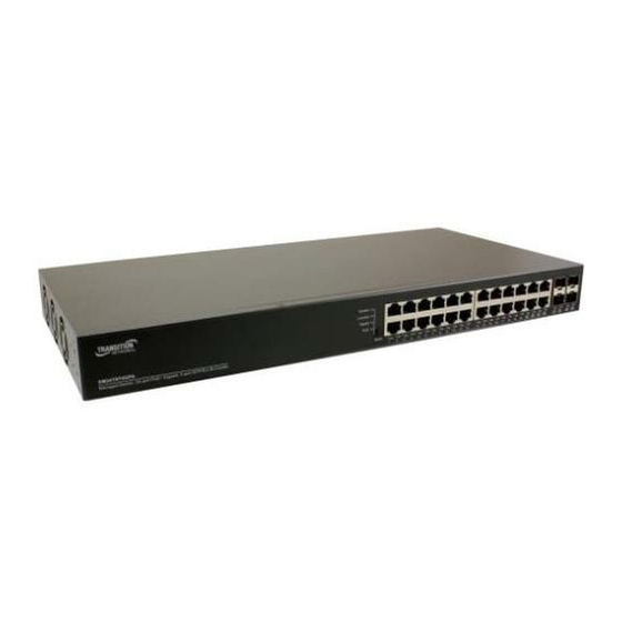
1-4. View of SM24TAT4GPA Fig. 1-1 Full View of SM24TAT4GPA 1-4-1. Front Panel (Button, LEDs and Plugs) There are 20-Port 10/100/1000Base-T + 4 100/1000 SFP/RJ-45 Combo slots on the front panel of the switch. The LED display area, located on the left side of the panel, contains a Power LED, which indicates the power status and 24 ports working status of the switch. - Page 11 Mode Button Indicators Pressing time Function (seconds) <3 Switch mode LED indicator 3~10 Warm boot >10 Reset factory default+ reboot Mode LED Indicators Mode LED Color Function Lit Green when Link/Act mode enable Link/Act Green Off when Link/Act mode disable Lit Green when Speed mode enable Speed Green...
-
Page 12: The Rear Panel
1-4-2. the Rear Panel Fig. 1-3 Rear View of SM24TAT4GPA Publication date: Mar. 2016 33600 Rev B... -
Page 13: Installation
⇒ Wear a grounding device to avoid the damage from electrostatic discharge ⇒ Be sure that power is OFF before you plug the power cord Installing Optional SFP Transceivers to the SM24TAT4GPA Switch Note: If you have no modules, please skip this section. - Page 14 Now, you can start having the switch in operation. Power On The switch supports 100-240 VAC, 50-60 Hz power supply. The power supply will automatically convert the local AC power source to DC power. It does not matter whether any connection plugged into the switch or not when power on, even modules as well.
-
Page 15: Cabling Requirements
2-1-2. Cabling Requirements To help ensure a successful installation and keep the network performance good, please take a care on the cabling requirement. Cables with worse specification will render the LAN to work poorly. 2-1-2-1. Cabling Requirements for TP Ports ⇒... - Page 16 Case1: All switch ports are in the same local area network. Every port can access each other (See Fig. 2-2) * Fig. 2-2 No VLAN Configuration Diagram If VLAN is enabled and configured, each node in the network that can communicate each other directly is bounded in the same VLAN area.
- Page 17 Case 2b: Port-based VLAN (See Fig.2-4). Fig. 2-4 Port-based VLAN Diagram 1. VLAN1 members could not access VLAN2, VLAN3 and VLAN4 members. 2. VLAN2 members could not access VLAN1 and VLAN3 members, but they could access VLAN4 members. VLAN3 members could not access VLAN1, VLAN2 and VLAN4. 4.
-
Page 18: Configuring The Management Agent Of Sm24Tat4Gpa
Note: If PC directly connects to the switch, you have to setup the same subnet mask between them. But, subnet mask may be different for the PC in the remote site. Please refer to Fig. 2-6 about the SM24TAT4GPA default IP address information. Run web browser and follow the menu. Please refer to Chapter 4. -
Page 19: Ip Address Assignment
2-1-4. IP Address Assignment For IP address configuration, there are three parameters needed to be filled in. They are IP address, Subnet Mask, Default Gateway and DNS. IP address: The address of the network device in the network is used for internetworking communication. - Page 20 Class C: IP address range between 192.0.0.0 and 223.255.255.255. Each class C network has a 24-bit network prefix followed 8-bit host address. There are 2,097,152 (2^21)/24 networks able to be defined with a maximum of 254 (2^8 –2) hosts per network. Bit # 0 1 2 3 23 24 Network address...
- Page 21 Not all IP address is available in the sub-netted network. Two special addresses are reserved. They are the addresses with all zero’s and all one’s host number. For example, an IP address 128.1.2.128, what IP address reserved will be looked like? All 0s mean the network itself, and all 1s mean IP broadcast. 128.1.2.128/25 Network Subnet...
- Page 22 65536 65534 Table 2-3 According to the scheme above, a subnet mask 255.255.255.0 will partition a network with the class C. It means there will have a maximum of 254 effective nodes existed in this sub-netted network and is considered a physical network in an autonomous network.
-
Page 23: Typical Applications
2-2. Typical Applications The SM24TAT4GPA has 24 Gigabit Ethernet TP ports with auto MDIX and four slots for the pluggable module supporting comprehensive fiber types of connection, including LC and BiDi-LC SFP modules. For more details on the specification of the switch, please refer to Appendix A. - Page 24 Fig. 2-11 Peer-to-peer Network Connection Fig. 2-12 Office Network Connection Publication date: Mar. 2016 33600 Rev B...
-
Page 25: Basic Concept And Management
3. Basic Concept and Management This chapter will tell you the basic concept of features to manage this switch and how they work. 3-1. What is the Ethernet Ethernet originated and was implemented at Xerox in Palo Alto, CA in 1973 and was successfully commercialized by Digital Equipment Corporation (DEC), Intel and Xerox (DIX) in 1980. -
Page 26: Logical Link Control (Llc)
IEEE 802.2 LLC Data Link Layer IEEE802.3 CSMA/CD MAC IEEE 802.3 PLS Physical Layer ANSI X3T9.5 PMD IEEE 802.3 Fiber Coaxial/STP/UTP This above diagram shows the Ethernet architecture, LLC sub-layer and MAC sub-layer, which are responded to the Data Link layer, and transceivers, which are responded to the Physical layer in OSI model. - Page 27 The table 3-1 is the format of LLC PDU. It comprises four fields, DSAP, SSAP, Control and Information. The DSAP address field identifies the one or more service access points, in which the I/G bit indicates it is individual or group address. If all bit of DSAP is 1s, it’s a global address.
-
Page 28: Media Access Control (Mac)
3-3. Media Access Control (MAC) 3-3-1. MAC Addressing Because LAN is composed of many nodes, for the data exchanged among these nodes, each node must have its own unique address to identify who should send the data or should receive the data. In OSI model, each layer provides its own mean to identify the unique address in some form, for example, IP address in network layer. - Page 29 Type/Length Data Pad bit if any 46-1500 Table. 3-4 Ethernet frame structure Preamble (PRE) —The PRE is 7-byte long with alternating pattern of ones and zeros used to tell the receiving node that a frame is coming, and to synchronize the physical receiver with the incoming bit stream. The preamble pattern is: 10101010 10101010 10101010 10101010 10101010 10101010 10101010 Start-of-frame delimiter (SFD) —...
- Page 30 redundancy check (CRC) value, and is a check sum computed with DA, SA, through the end of the data field with the following polynomial. It is created by the sending MAC and recalculated by the receiving MAC to check if the packet is damaged or not. How does a MAC work? The MAC sub-layer has two primary jobs to do: 1.
- Page 31 Ethernet MAC transmits frames in half-duplex and full-duplex ways. In half- duplex operation mode, the MAC can either transmit or receive frame at a moment, but cannot do both jobs at the same time. As the transmission of a MAC frame with the half-duplex operation exists only in the same collision domain, the carrier signal needs to spend time to travel to reach the targeted device.
- Page 32 Parameter 10Base 100Base 1000Base value/LAN Max. collision 100 meters for UTP 100 meters for UTP domain DTE to 100 meters 412 meters for fiber 316 meters for fiber Max. collision domain with 2500 meters 205 meters 200 meters repeater Slot time 512 bit times 512 bit times 512 bit times...
-
Page 33: Flow Control
PAUSE operation can not be used to inhibit the transmission of MAC control frame. Normally, in 10Mbps and 100Mbps Ethernet, only symmetric flow control is supported. However, some switches (e.g. SM24TAT4GPA) support not only symmetric but asymmetric flow controls for the special application. In Gigabit Ethernet, both symmetric flow control and asymmetric flow control are supported. - Page 34 Frame Reception In essence, the frame reception is the same in both operations of half duplex and full duplex, except that full-duplex operation uses two buffers to transmit and receive the frame independently. The receiving node always “listens” if there is traffic running over the medium when it is not receiving a frame.
- Page 35 (TCI) used to provide user priority and VLAN ID, which are explained respectively in the following table. Bits 15-13 User Priority 7-0, 0 is lowest priority CFI (Canonical Format Indicator) Bit 12 1: RIF field is present in the tag header 0: No RIF field is present VID (VLAN Identifier) 0x000: Null VID.
-
Page 36: How Does A Switch Work
3-5. How does a switch work? The switch is a layer 2 Ethernet Switch equipped with 24 Gigabit Ethernet ports and 4 optional modules which support Gigabit Ethernet or 100M Ethernet. Each port on it is an independent LAN segment and thus has 26 LAN segments and 26 collision domains, contrast to the traditional shared Ethernet HUB in which all ports share the same media and use the same collision domain and thus limit the bandwidth utilization. - Page 37 Fig.3-6 Collision Domain Extended Distance Limitations: The diameter of a half-duplex LAN segment is determined by its maximum propagation delay time. For example, in 10M LAN, the most distance of a LAN segment using yellow cable is 2500 meters and 185 meters when using coaxial cable.
- Page 38 Fig. 3-7 How does a switch operate? A Layer 2 switch uses some features of the Data Link layer in OSI model to forward the packet to the destination port(s). Here we introduce some important features of a switch and how they work. MAC address table When a packet is received on a port of switch, the switch first checks if the packet good or bad and extracts the source MAC address (SA) and destination...
- Page 39 chips may support different schedule algorithms. Most common schedulers are: FCFS: First Come First Service. Strictly Priority: All High before Low. Weighted Round Robin: Set a weight figure to the packet with a priority level, say 5-7, and next, set another weight to the packet with a priority level, say 2-4 and so on.
-
Page 40: Virtual Lan
3-6. Virtual LAN What is a VLAN? It is a subset of a LAN. Before we discuss VLAN, we must understand what LAN is. In general, a LAN is composed of different physical network segments bridged by switches or bridges which attach to end stations in the same broadcast domain. - Page 41 Fig. 3-9 Now we apply VLAN technology to configure the system shown as the figure above. We can partition the users into the different logical networks which have their own broadcast domain. The traffic will not disturb among these logical networks. The users 1x (x denotes a ~ d) are members of VLAN 1.
- Page 42 Terminology Tagged Frame: A frame, carrying a tag field following the source MAC address, is four bytes long and contains VLAN protocol ID and tag control information composed of user priority, Canonical Format Indicator (CFI) and optional VLAN identifier (VID). Normally, the maximal length of a tagged frame is 1522 bytes.
- Page 43 Port VLAN Identifier: VLAN identifier of a port. It also can be referred to as PVID. When an untagged frame or a priority-tagged frame is received, the frame will be inserted the PVID of that port in the VLAN tag field. The frame with VID assigned by a port is called PVID.
- Page 44 VLAN to learn or look up the membership information of the VLAN. In SM24TAT4GPA, you can choose a VID for sharing filtering database in Shared VID field if you wish to use the existed filtering database. For a specified VLAN, when a MAC address is learned by a switch, VLAN will use this formation to make forwarding decision.
- Page 45 Name Port Members Marketing 1,2,3,4,5 Service 6,7,20,21,22 Sales 8,9,10,11,12,13,14,15,16 Administration 17,18,19,23,24 Table 3-5 Next, assigns IP address to each VLAN. Usually, we use 10.x.x.x as internal IP block. Because there are total four VLANs in the network, we must assign 4 IP blocks to each of them.
-
Page 46: Operation Of Web-Based Management
Gigabit dual media ports. With this facility, you can easily access and monitor the status like MIBs, port activity, and multicast traffic through any ports on the switch. The default values of SM24TAT4GPA are listed in the table below: IP Address 192.168.1.77 Subnet Mask 255.255.255.0... -
Page 47: Web Management Home Overview
4-1. Web Management Home Overview After login, System Information would be displayed as Fig. 4-2 illustrated. This page lists default values and shows you the basic information of the switch, including “Switch Status”, “TP Port Status”, “Fiber Port Status”, “Aggregation”, “VLAN”, “Mirror”, “SNMP”, and “Maximum Packet Length”. - Page 48 Root Configuration Monitoring Maintenance Publication date: Mar. 2016 33600 Rev B...
-
Page 49: Configuration
4-2. Configuration Configuration includes the following functions: System Information, Ports Configuration, VLAN Mode Configuration, VLAN Group Configuration, VLAN Isolation, PoE, Aggregation, IGMP Snooping, Mirroring, Qos, Loop detection, Broadcast Storm Protection and SNMP. Configuration System Information Ports Configuration VLAN Mode VLAN Group VLAN Isolation Aggregation IGMP Snooping... -
Page 50: System Information
4-2-1. System Information System configuration is one of the most important functions. Without a proper setting, network administrator would not be able to manage the device. The switch supports manual IP address setting. Fig. 4-3 Publication date: Mar. 2016 33600 Rev B... - Page 51 Device Name: Set a special name for this switch. Up to 16 characters are allowed in this parameter. Any alphanumeric character and null are acceptable. Default: SM24TAT4GPA System Contact: The textual identification of the contact person for this managed node, together with information on how to contact this person.
- Page 52 255, and the allowed content is the ASCII characters from 32 to 126. System Location: The physical location of this node (e.g., telephone closet, 3rd floor). The allowed string length is 0 to 255, and the allowed content is the ASCII characters from 32 to 126.
- Page 53 meet the routing rules predefined in the device. If a packet does not meet the criteria for other pre-defined path, it must be forwarded to a default router on a default path. This means any packet with undefined IP address in the routing table will be sent to this device unconditionally. Default: 192.168.1.254 Management VLAN: Show the management VLAN number.
-
Page 54: Port Configuration
4-2-2. Port Configuration Function name: Port Configuration Function description: Port Configuration is applied for the settings of the ports on the switch. By this function, you can set or reset the values for Mode and Flow Control. Others you could set the power saving mode for switch power consumption. Fig. - Page 55 Parameter description: Enable Jumbo Frames: This function support jumbo frames of up to 9600 bytes, Just tick the check box () to enable it. Default: disable Perfect Reach/Power Saving Mode: This function supports Power Saving and perfect Reach, Just select with the Full/ Link-up/ Link-down/ Disable Default: disable Link:...
-
Page 56: Vlan Mode Configuration
4-2-3. VLAN Mode Configuration Switch supports Port-based VLAN and Tag-based VLAN (802.1q). Its VLAN mode supports 10 active VLANs and the available VLAN ID range is from 1~4094. VLAN configuration is used to divide a LAN into smaller ones. With proper configuration, you can gain not only improved security and increased performance, but also save a lot of VLAN management effort. -
Page 57: Vlan Group Configuration
4-2-4. VLAN Group Configuration Function name: Tag-Based VLAN Configuration (Tag based VLAN mode) Function description: The VLAN membership configuration for the selected switch can be monitored and modified here. Up to 4094 VLANs are supported. This page allows for adding and deleting VLANs as well as adding and deleting port members of each VLAN. - Page 58 Parameter description: VID: VLAN identifier. Each tag-based VLAN group has a unique VID. It appears only in tag-based mode. Member: In modify function this is used to enable or disable if a port is a member of the new added VLAN, “Enable” means it is a member of the VLAN. Just tick the check box () beside the port x to enable it.
- Page 59 Function name: Port-Based VLAN Configuration (Port-based VLAN mode) Function description: It shows the information of VLAN Groups, and allows administrators to maintain them by modifying and deleting each VLAN group. User also can add a new VLAN group by inputting a new VLAN name and VLAN ID. If you are in port-based VLAN, it will just show the ID、Member of the existed port-based VLAN group.
- Page 60 Fig. 4-7 Add or Remove VLAN Member Parameter description: ID (Group ID): When you want to edit a VLAN group, you must select the Group ID field. Then, you will enter Tag Base VLAN Group Setting or Port Base VLAN Group Setting page, which depends on your VLAN mode selection.
-
Page 61: Vlan Port Isolation Configuration
4-2-5. VLAN Port Isolation Configuration Function name: Port Isolation Configuration Function description: Port Isolation provides for an apparatus and method to isolate ports on layer 2 switches on the same VLAN to restrict traffic flow. The apparatus comprises a switch having said plurality of ports, each port configured as a protected port or a non-protected port. -
Page 62: Poe
4-2-6. PoE Power Over Ethernet (PoE) technology allows IP telephones, wireless LAN access points, and other powered devices (PDs) to receive power and transfer data over existing LAN cabling. Function name: Power over Ethernet configuration Function description: In PoE Port Management function, user can configure the settings about PoE. The switch complies with IEEE 802.3af protocol and be capable of detecting automatically that whether the device linked to the port on the switch is PD (Powered Device) or not. - Page 63 Parameter description: PoE Enabled: To evoke to enable which port supply the power to the PD. Priority: Three options are offered for the user to choose, including Normal, Low and High. Default is Normal. The switch will stop supplying the power to the port based on the order of the priority LowNormalHigh in case total power required by all PDs linked to the switch excesses the power limit.
-
Page 64: Aggregation
4-2-7. Aggregation The Aggregation (Port Trunking) Configuration is used to configure the settings of Link Aggregation. You can bundle ports by same speed, MAC, and full duplex to be a single logical port, thus the logical port can aggregate the bandwidth of these ports. -
Page 65: Igmp Snooping
4-2-8. IGMP Snooping Function name: IGMP Snooping Configuration Function description: IGMP Snooping lets administrators configure a switch to constrain multicast traffic by listening to (IGMP). After finishing the Internet Group Management Protocol settings, please press <Apply> button to start up the function. Fig. - Page 66 Default: enable VLAN ID: At the IGMP Enable mode being selected, it will list the VLAN ID number. IGMP Snooping Enabled: ) After IGMP Enabled function start up then user can tick the check box ( enable this function. Default: enable IGMP Querying Enabled: ) After IGMP Enabled function start up then user can tick the check box (...
-
Page 67: Mirroring Configuration
4-2-9. Mirroring Configuration Function name: Mirror Configuration Function description: Mirror Configuration is provided to monitor the traffic in the network. This switch supports one-port mirror multi-ports. For example, we assume that Port A and Port B are Source Ports, and Port C is Mirror Port respectively, thus, the traffic passing through Port A and Port B will be copied to Port C for monitor purpose. -
Page 68: Qos(Quality Of Service) Configuration
4-2-10. QoS(Quality of Service) Configuration offers powerful QoS function. This function supports VLAN-tagged switch priority that can make precedence of 8 priorities, and DSCP (Differentiated Services Code Point) on Layer 3 of network framework. Fig. 4-13 QoS Configuration Function name: QoS Configuration Function description: While setting QoS function, please select QoS Mode in drop-down menu at... - Page 69 Queue normal, Priority 1 is mapping to Queue low, Priority 2 is mapping to Queue low, Priority 3 is mapping to Queue normal, Priority 4 is mapping to Queue medium, Priority 5 is mapping to Queue medium, Priority 6 is mapping to Queue high, and Priority 0 is mapping to Queue high.
- Page 70 DSCP Configuration: 64 kinds of priority traffic as mentioned above, user can set up any of Queue (low, normal, medium, high). In default, Priority 0~63 are mapping to Queue high. Fig. 4-15 DSCP Setting Publication date: Mar. 2016 33600 Rev B...
-
Page 71: Loop Detection
4-2-11. Loop Detection Function name: Loop Detection Configuration Function description: The loop detection is used to detect the presence of traffic. When switch receives packet’s (looping detection frame) MAC address the same as oneself from port, show Loop detection happens. The port will be locked when it received the looping detection frames. - Page 72 Parameter description: Mode: Controls whether Loop is enabled (as a whole). Detection Unlock Time: The period (in seconds) for which a port will be kept disabled in the event of a loop is detected (and the port action is to shut down the port). State: Show the status of the port.
-
Page 73: Broadcast Storm Protection
4-2-12. Broadcast Storm Protection Function name: Broadcast Storm Protection configuration Function description: When the broadcast packets received by the switch exceed the threshold configured, the port will be blocked for a period of time which can be set. After a configured time, the switch will detect whether the broadcast packets received on the port still exceed the threshold. - Page 74 Parameter description: Mode: Controls whether Broadcast Storm Protection is enabled (as a whole). Packet Per Second: It is a threshold. When the broadcast packet traffic in a second is higher than the threshold configured, the Broadcast Storm Protection enable. Unlock Time: The period (in seconds) for which a port will be kept disabled in the event of a loop is detected (and the port action is to shut down the port).
-
Page 75: Snmp
4-2-13. SNMP Any Network Management System (NMS) running the Simple Network Management Protocol (SNMP) can manage the Managed devices equipped with SNMP agent, provided that the Management Information Base (MIB) is installed correctly on the managed devices. It is a protocol used to govern the transfer of information between SNMP manager and agent and traverses the Object Identity (OID) of the management Information Base (MIB), described in the form of SMI syntax. -
Page 76: Rstp/Stp
Parameters description: SNMP enable: The term SNMP enable here is used for the activation or de-activation of SNMP. Default is “Disable”. Read/write/Trap Community: Community name is used as password for authenticating if the requesting network management unit belongs to the same community group. - Page 77 This screen is used to display the RSTP system configuration and set the values of the parameters. Fig. 4-19 RSTP Configuration Publication date: Mar. 2016 33600 Rev B...
- Page 78 Parameter description: System Priority: System priority is used in determining the root switch, root port and designated port. The switch with the highest priority (lowest numeric value) becomes the STP root switch. If all switches have the same priority, the switch with the lowest MAC address will then become the root switch.
-
Page 79: Monitoring
4-3. Monitoring There are six functions contained in the monitoring function. Monitoring Statistics Overview Detailed Statistics RSTP/STP IGMP Status PoE Status Ping Publication date: Mar. 2016 33600 Rev B... -
Page 80: Statistics Overview
4-3-1. Statistics Overview Function name: Statistics Overview for all ports Function description: The section describes to the Port statistics information and provides overview of general traffic statistics for all switch ports. Fig. 4-20 Statistics Overview for all ports Parameter description: Tx/Rx Bytes: The number of received and transmitted bytes per port. -
Page 81: Detailed Statistics
4-3-2. Detailed Statistics Function name: Detailed Statistics Function description: Display the detailed counting number of each port’s traffic. In the Fig. 4-21, the window can show all counter information each port at one time. Fig. 4-21 Detailed Statistics for each port Parameter description: Rx Packets: The counting number of the packet received. - Page 82 Tx Packets: The counting number of the packet transmitted. TX Octets: Total transmitted bytes. Tx High Priority Packets: Number of Tx packets classified as high priority. Tx Low Priority Packets: Number of Tx packets classified as low priority. Tx Broadcast: Show the counting number of the transmitted broadcast packet.
-
Page 83: Rstp/Stp Status
Number of 256 ~ 511-byte frames in good and bad packets transmitted. Tx 512-1023 Bytes: Number of 512 ~ 1023-byte frames in good and bad packets transmitted. Tx 1024-Bytes: Number of 1024-max_length-byte frames in good and bad packets transmitted. Rx CRC/Alignment: Number of Alignment errors and CRC error packets received. - Page 84 Fig. 4-22 RSTP Status Parameter description: RSTP VLAN Bridge Overview: VLAN Id: Show the VLAN Id. Bridge Id: Show this switch’s current bridge priority setting and bridge ID which stands for the MAC address of this switch. Hello Time: Show the current hello time of the root bridge. Hello time is a time interval specified by root bridge, used to request all other bridges periodically sending hello message every “hello time”...
- Page 85 Max Age: Show the root bridge’s current max age time. Fwd Delay: Show the root bridge’s forward delay time. Topology: Show the root bridge’s spanning tree topology. Root Id: Show root bridge ID of this network segment. If this switch is a root bridge, the “This switch is Root”...
-
Page 86: Igmp Status
4-3-4. IGMP Status Function name: IGMP Status Function description: Display IGMP status. In Fig. 4-23, the window shows VLAN ID for each multicast group. Fig. 4-23 IGMP Status Parameter description: VLAN Id: Show VLAN Id for each multicast group. Querier: Show the group membership queries status. - Page 87 V3 Reports: When a host receives a group membership query, it identifies the groups associated with the query and determines to which groups it belongs. The host then sets a timer, with a value less than the Max Response Time field in the query, for each group to which it belongs. It Calculate the number of times of IGMPV3 report.
-
Page 88: Poe Status
4-3-5. PoE Status Function name: PoE State Function description: Display the information about the PoE status. Fig. 4-24 Parameter description: Power Reservation: The watts are supplied by the PoE./ The maximal power that the switch can supply (Read Only). Port No: Port number. - Page 89 Five PD Classes are defined: Class 0: Max. power 15.4 W Class 1: Max. power 4.0 W Class 2: Max. power 7.0 W Class 3: Max. power 15.4 W Class 4: Max. power 30.0 W Power: The Power Used shows how much power the PD currently is using. Current The Power Used shows how much current the PD currently is using.
-
Page 90: Ping Status
4-3-6. Ping Status Function name: Ping Status Function description: To set up target IP address for ping function and display ping status. In Fig. 4- 25, the window shows the ping information. Fig. 4-25 Ping Parameter description: Ping Parameters: Target IP address: Set up a Target IP address to ping. - Page 91 Ping Results: Target IP address: Show the active target IP address. Status: Show the result of the ping status. Received replies: Show the received replies number of times. Request timeouts: Show the timeout of request. Average Response times (In ms): Show the average response time in milliseconds.
-
Page 92: Maintenance
4-4. Maintenance There are five functions contained in the maintenance function. Maintenance Warm Restart Factory Default Software Upgrade Configuration File Transfer Logout Publication date: Mar. 2016 33600 Rev B... -
Page 93: Warm Restart
4-4-1. Warm Restart Switch offers many approaches to reboot your switch, such as: power up, hardware reset and software reset. You can press Mode button in the front panel of your switch to reset the device and to retrieve default settings. After upgrading software, you have to reboot the device to have new configuration take effect. -
Page 94: Factory Default
4-4-2. Factory Default Function name: Factory Default Function description: Factory Default provides the function to retrieve default settings and replace current configuration. Except the IP address setting, all settings will be restored to the factory default values when “Factory Default” function is performed. -
Page 95: Software Upgrade
4-4-3. Software Upgrade Function name: Software Upgrade Function description: You can just click Browse button to retrieve the file you want in your system to upgrade your switch. Fig. 4-28 Software Upgrade Publication date: Mar. 2016 33600 Rev B... -
Page 96: Configuration File Transfer
4-4-4. Configuration File Transfer Function name: Configuration File Transfer Function description: You can backup your switch’s configuration file into your computer folder in case accident happens. In addition, uploading backup configuration file into a new or a crashed switch can save much time and avoid mistakes. Fig. -
Page 97: Logout
4-4-5. Logout In addition to auto logout function we just mentioned in system configuration section, the switch also allows administrators to logout manually by Logout function. Function name: Logout Function description: The switch allows you to logout the system to prevent other users from the system without the permission. -
Page 98: Maintenance
The connection ports on another must be connection ports. Please check if connection ports are used on that SM24TAT4GPA. Please check the uplink setup of the SM24TAT4GPA to verify the uplink function is enabled. 3. The console interface cannot appear on the console port connection. - Page 99 USA: 7 AM until 8 PM CST Monday to Friday. Out of Hours the calls will be answered by an on-call engineer. Live Help Online Support: Chat live with a Transition Networks representative at http://transition.com/TransitionNetworks/TechSupport/ContactUs.aspx. Warranty This warranty is your only remedy. No other warranties, such as fitness for a particular purpose, are expressed or implied.
- Page 100 The customer must pay for the non-compliant product(s) return transportation costs to Transition Networks for evaluation of said product(s) for repair or replacement. Transition Networks will pay for the shipping of the repaired or replaced in-warranty product(s) back to the customer (any and all customs charges, tariffs, or/and taxes are the customer's responsibility).
- Page 101 AS FITNESS FOR A PARTICULAR PURPOSE, ARE EXPRESSED OR IMPLIED. TRANSITION NETWORKS IS NOT LIABLE FOR ANY SPECIAL, INDIRECT, INCIDENTAL OR CONSEQUENTIAL DAMAGES OR LOSSES, INCLUDING LOSS OF DATA, ARISING FROM ANY CAUSE OR THEORY. AUTHORIZED RESELLERS ARE NOT AUTHORIZED TO EXTEND ANY DIFFERENT WARRANTY ON TRANSITION NETWORKS'S BEHALF.
-
Page 102: Appendix A Technical Specifications
Appendix A Technical Specifications Features • 20 (10/100/1000Mbps) Gigabit Ethernet (TP) switching ports are compliant with IEEE802.3, 802.3u, 802.3z and 802.3ab. • 4 Gigabit TP/SFP fibers are dual media ports with auto detected function. • Non-blocking store-and-forward shared-memory Web-Smart switched. •... - Page 103 Hardware Specifications Standard Compliance: IEEE802.3/802.3ab / 802.3z / 802.3u / 802.3x Network Interface: Configuration Mode Connector Port 10/100/1000Mbps Gigabit TP 1 - 20 NWay TP (RJ-45) 21 - 24 1000 FDX *SFP 1000Base-SX Gigabit Fiber (Option) 21 - 24 1000 FDX *SFP 1000Base-LX Gigabit Fiber (Option)
- Page 104 Diagnostic LEDs: System LED : Power Per Port LED: 10/100/1000M TP Port 1 to 20 : LINK/ACT, SPD 1000M SFP Fiber Port 21 to 24 : LINK/ACT, SPD The System LED displays red light alarm for the 4 cases below: 1.
- Page 105 10900 Red Circle Drive Minnetonka, MN 55343 USA Tel: 952- 941-7600 or 1-800-526-9267 Fax: 952-941-2322 Copyright © 2015 Transition Networks. All rights reserved. SM24TAT4GPA 24-Port 10/100/1000Base-T Managed POE plus Switch User Manual, 33600 Rev. B Publication date: Mar. 2016 33600 Rev B...
Need help?
Do you have a question about the SM24TAT4GPA and is the answer not in the manual?
Questions and answers