
Related Manuals for Transition Networks SM4T4DPA


Summary of Contents for Transition Networks SM4T4DPA
- Page 1 SM4T4DPA 4-port 10/100/1000Base-T, 4-port 100/1000 SFP Managed Switch Installation and Getting Started Guide...
- Page 2 ABOUT THIS GUIDE PURPOSE This guide gives specific information on how to operate and use the management functions of the switch. AUDIENCE The guide is intended for use by network administrators who are responsible for operating and maintaining network equipment; consequently, it assumes a basic working knowledge of general switch functions, the Internet Protocol (IP), and Simple Network Management Protocol (SNMP).
- Page 3 REVISION HISTORY Revision Date 25/July/2012 Rev.A1 25-July-12...
-
Page 4: Table Of Contents
Contents ABOUT THIS GUIDE ..........................i INTRODUCTION ............................. 1 OVERVIEW ............................1 DESCRIPTION OF HARDWARE ......................4 NETWORK PLANNING .......................... 6 INTRODUCTION TO SWITCHING ..................... 6 APPLICATION EXAMPLES ....................... 6 INSTALLING THE SWITCH........................9 SELECTING A SITE ........................... 9 ETHERNET CABLING ........................9 EQUIPMENT CHECKLIST ....................... - Page 5 TWISTED-PAIR CABLE AND PIN ASSIGNMENTS ............... 29 STRAIGHT- THROUGH WIRING ......................30 1000BASE-T PIN ASSIGNMENTS ....................33 CABLE TESTING FOR EXISTING CATEGORY 5 CABLE............. 34 FIBER STANDARDS ..........................34 C SPECIFICATIONS ..........................36 COMPLIANCES ............................ 39 Rev.A1 25-July-12...
-
Page 6: Introduction
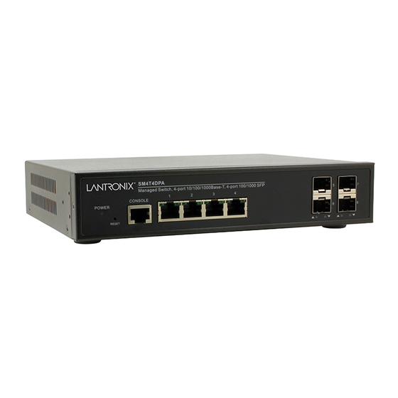
INTRODUCTION OVERVIEW The SM4T4DPA Switch is a managed Ethernet switches which includes with 4 10/100/1000Base-T ports plus 4 dual speed 100/1000 SFP slots, it provides ideal flexibility to design suitable network infrastructure for business requirement. Rev.A1 25-July-12... - Page 7 Front of the Switches Figure 1: SM4T4DPA Power LED Console Switch TP Port LEDs 100/1000 SFP 10/100/1000Base-T RJ-45 Ports Figure 2: Back of the Switches AC Power Socket Rev.A1 25-July-12...
- Page 8 The switch performs a wire-speed, non-blocking switching fabric. SWITCH This allows wire-speed transport of multiple packets at low ARCHITECTURE latency on all ports simultaneously. The switch also features full-duplex capability on all ports, which effectively doubles the bandwidth of each connection. This switch uses store-and-forward technology to ensure maximum data integrity.
-
Page 9: Description Of Hardware
SFP TRANSCEIVER SLOTS SM4T4DPA supports the Small Form Factor Pluggable (SFP) transceiver. Please visit our web page for the detail of the optional SFP modules: http://www.transition.com/TransitionNetworks/Landing/SFP-XFP/SFP-XFP.aspx Rev.A1... - Page 10 PORT AND SYSTEM The SM4T4DPA switch includes a display panel for system STATUS LEDS and port indications that simplify installation and network troubleshooting. The LEDs, which are located on left hand side of the front panel for easy viewing. Details are shown below and described in the following tables.
-
Page 11: Network Planning
NETWORK PLANNING INTRODUCTION A network switch allows simultaneous transmission of multiple TO SWITCHING packets; it can partition a network more efficiently than bridges or routers. Therefore the switch has been recognized as one of the most important device for today’s networking technology. When performance bottlenecks are caused by congestion at the network access point such as file server, the device can be connected directly to a switched port. - Page 12 Figure 4: Network Connection between Remote Site and Central Site Figure 5: Peer-to-peer Network Connection Rev.A1 25-July-12...
- Page 13 Figure 6: Office Network Connection Rev.A1 25-July-12...
-
Page 14: Installing The Switch
Make sure the twisted-pair Ethernet cable is always ◆ routed away from power lines, radios, transmitters or any other electrical interference. Make sure that SM4T4DPA Switch is connected to a separate ◆ grounded power outlet that provides 100 to 240 VAC, 50 to 60 Hz. -
Page 15: Equipment Checklist
CHECKLIST you have received all the components. Then, before beginning the installation, be sure you have all other necessary installation equipment. PACKAGE SM4T4DPA Management Switch CONTENTS Four adhesive rubber feet Mounting Accessory (for 19” Rack Shelf, Optional) ... - Page 16 Circuit Overloading: Be sure that the supply circuit to the rack assembly is not overloaded. Grounding: Rack-mounted equipment should be properly grounded. TO Rack-mount Devices: Step1. Attach the brackets to the device using the screws provided in the Mounting Accessory.
-
Page 17: Installing An Optional Sfp Transceiver
DESKTOP OR SHELF MOUNTING: Step1. Attach the four adhesive rubber feet to the bottom of the first switch. Figure 11: Attaching the Adhesive Rubber Feet Step2. Set the device on a flat surface near an AC power source, making sure there are at least two inches of space on all sides for proper air flow. -
Page 18: Connecting To A Power Source
Figure 12: Inserting an SFP Transceiver into a Slot TO Install a SFP transceiver, do the following: Step1. Consider network and cabling requirements to select an appropriate SFP transceiver type. Step2. Insert the transceiver with the optical connector facing outward and the slot connector facing down. -
Page 19: Connecting To The Console Port
For International use, you may need to change the AC ARNING line cord. You must use a line cord set that has been approved for the socket type in your country. CONNECTING RJ-45 serial port switch’s front panel TO THE used connect switch... - Page 20 Figure 14: Serial Port (RJ-45) Pin-Out 2 TXD 5 GND 3 RXD WIRING MAP FOR SERIAL CABLE Table 3: Serial Cable Wiring Switch’s 8-Pin Serial Port Null Modem PC’s 9-Pin DTE Port 2 RXD (receive data) 3 TXD (transmit data) ----------------- 3 RXD (receive data) -----------------...
-
Page 21: Operation Of Web-Based Management
“admin”. For the first time to use, please enter the default username and password, and then click the <Login> button. The login process now is completed. SM4T4DPA web user interface: 192.168.1.77 If you need to configuration the function or parameter then you can refer the detail in the User Guide. - Page 22 SM4T4DPA web help function : Rev.A1 25-July-12...
-
Page 23: Making Network Connections
MAKING NETWORK CONNECTIONS CONNECTING The switch is designed to be connected to 10, 100 or 1000Mbps NETWORK network cards in PCs and servers, as well as to other switches DEVICES and hubs. It may also be connected to remote devices using optional SFP transceivers. - Page 24 Step2. If the device is a network card and the switch is in the wiring closet, attach the other end of the cable segment to a modular wall outlet that is connected to the wiring closet. (See the section “Network Wiring Connections.”) Otherwise, attach the other end to an available port on the switch.
- Page 25 FIBER OPTIC An optional Gigabit SFP transceiver can be used for a SFP DEVICES backbone connection between switches, or for connecting to a high-speed server. Each single-mode fiber port requires 9/125 micron single-mode fiber optic cable with an LC connector at both ends.
- Page 26 Figure 18: Making Fiber Port Connections Step4. As a connection is made, check the Link LED on the switch corresponding to the port to be sure that the connection is valid. The fiber optic ports operate at 1 Gbps. The maximum length for fiber optic cable operating “1000 Mbps Gigabit at Gigabit speed will depend on the fiber type as listed under Ethernet Collision...
- Page 27 CONNECTIVITY RULES When adding hubs to your network, please note that because switches break up the path for connected devices into separate collision domains, you should not include the switch or connected cabling in your calculations for cascade length involving other devices. 1000BASE-T CABLE All Category 5 UTP cables that are used for REQUIREMENTS...
- Page 28 Table 7: Maximum 1000BASE-LX Single Fiber Gigabit Fiber Cable Length Fiber Size Fiber Bandwidth Maximum Cable Length Connector Single-mode 20km (12.42miles) BIDI TX-1310nm RX-1550nm Single-mode 20km (12.42miles) BIDI TX-1550nm RX-1310nm 100 MBPS FAST ETHERNET COLLISION DOMAIN Table 8: Maximum Fast Ethernet Cable Lengths Cable Type Maximum Cable Length Connector...
-
Page 29: Cable Labeling And Connection Records
CABLE LABELING AND CONNECTION RECORDS When planning a network installation, it is essential to label the opposing ends of cables and to record where each cable is connected. This will allow user to easily locate inter-connected devices, isolate faults and change your topology without need for unnecessary time consumption. -
Page 30: A Troubleshooting
Because the SM4T4DPA behave in this way (in compliance with the IEEE802.3 standard), if a device connected to the switch has a fixed configuration at full duplex, the device will not connect correctly to the switch. - Page 31 seriously impair network performance. new correctly-wired cable. For pinouts and correct cable wiring. A category 5 cable tester is a recommended tool every 100Base-TX 1000Base-T network installation. Improper Network Topologies. It is important to make sure you have a valid network topology. If you no longer experience the problems, the new topology is probably at fault.
- Page 32 defective adapter or cable if necessary. Rev.A1 25-July-12...
-
Page 33: Power And Cooling Problems
POWER AND COOLING PROBLEMS Installation If the power indicator does not turn on when the power cord is plugged in, you may have a problem with the power outlet, power cord, or internal power supply. However, if the unit powers off after running for a while, check for loose power connections, power losses or surges at the power outlet. -
Page 34: Cables
CABLES TWISTED-PAIR For 10/100BASE-TX connections, the twisted-pair cable must CABLE AND PIN have two pairs of wires. For 1000BASE-T connections the ASSIGNMENTS twisted-pair cable must have four pairs of wires. Each wire pair is identified by two different colors. For example, one wire might be green and the other, green with white stripes. -
Page 35: Straight- Through Wiring
using any RJ-45 port on this switch, you can use either straight-through or crossover cable. Table 11: 10/100BASE-TX MDI and MDI-X Port Pinouts MDI Signal Name MDI-X Signal Name Transmit Data plus (TD+) Receive Data plus (RD+) Transmit Data minus (TD-) Receive Data minus (RD-) Receive Data plus (RD+) Transmit Data plus (TD+) - Page 36 Rev.A1 25-July-12...
- Page 37 CROSSOVER If the twisted-pair cable is to join two ports and either both ports WIRING are labeled with an “X” (MDI-X) or neither port is labeled with an “X” (MDI), a crossover must be implemented in the wiring. (When auto-negotiation is enabled for any RJ-45 port on this switch, you can use either straight-through or crossover cable to connect to any device type.) You must connect all four wire pairs as shown in the following...
-
Page 38: 1000Base-Tpin Assignments
1000BASE-T All 1000BASE-T ports support automatic MDI/MDI-X operation, so you can use straight-through cables for all network connections to ASSIGNMENTS PCs or servers, or to other switches or hubs. The table below shows the 1000BASE-T MDI and MDI-X port pinouts. These ports require that all four pairs of wires be connected. -
Page 39: Cable Testing For Existing Category 5 Cable
CABLE TESTING Installed Category 5 cabling must pass tests for Attenuation, FOR EXISTING Near-End Crosstalk (NEXT), and Far-End Crosstalk (FEXT). CATEGORY 5 CABL This cable testing information is specified in the ANSI/TIA/EIA-TSB-67 standard. Additionally, cables must also pass test parameters for Return Loss and Equal-Level Far-End Crosstalk (ELFEXT). - Page 40 1285 to 1625 nm. The zero dispersion wavelength is in the 1310-nm region. Dispersion-Shifted Fiber G.653 Longer spans and extended reach. Optimized for Single-mode, 9/125-micron core operation in the region from 1500 to 1600-nm. 1550-nm Loss-Minimized Fiber G.654 Extended long-haul applications. Optimized for Single-mode, 9/125-micron core high-power transmission in the 1500 to 1600-nm region, with low loss in the 1550-nm band.
-
Page 41: C Specifications
C SPECIFICATIONS PHYSICAL CHARACTERISTICS PORTS 4 port 10/100/1000Mbps TP, 4 port 100/1000Mbps SFP Fiber ports NETWORK Ports 1-4: RJ-45 connector, auto MDI/X INTERFACE 10BASE-T: RJ-45 (100-ohm, UTP cable; Category 3 or better) 100BASE-TX: RJ-45 (100-ohm, UTP cable; Category 5 or better) 1000BASE-T: RJ-45 (100-ohm, UTP or STP cable;... - Page 42 SWITCH FEATURES FORWARDING Store-and-forward MODE THROUGHPUT 11.9 Mpps FLOW CONTROL Full Duplex: IEEE 802.3x Half Duplex: Back pressure MANAGEMENT FEATURES IN-BAND SSH/SSL, Telnet, SNMP, or HTTP MANAGEMENT OUT-OF-BAND RS-232 (RJ-45) console port MANAGEMENT SOFTWARE HTTP, TFTP in-band, Console out-of-band LOADING STANDARDS EEE 802.3 =>...
- Page 43 COMPLIANCES EMISSIONS EN55022 (CISPR 22) Class A EN 61000-3 FCC Class A CE Mark IMMUNITY EN 61000-4-2/3/4/5/6/8/11 EN 55024 Rev.A1 25-July-12...
-
Page 44: Compliances
COMPLIANCES 10BASE-T IEEE 802.3 specification for 10 Mbps Ethernet over two pairs of Category 3, 4, or 5 UTP cable 100BASE-TX IEEE 802.3u specification for 100 Mbps Ethernet over two pairs of Category 5 UTP cable 1000BASE-LH Specification for long-haul Gigabit Ethernet over two strands of 9/125 micron core fiber cable 1000BASE-LX IEEE 802.3z specification for Gigabit Ethernet over two... - Page 45 topology, and coaxial cable. The successor IEEE 802.3 standard provides for integration into the OSI model and extends the physical layer and media with repeaters and implementations that operate on fiber, thin coax and twisted-pair cable. FAST ETHERNET A 100 Mbps network communication system based on Ethernet and the CSMA/ CD access method.
- Page 46 MEDIA ACCESS A portion of the networking protocol that governs access to CONTROL (MAC) the transmission medium, facilitating the exchange of data between network nodes. An acronym for Management Information Base. It is a set of database objects that contains information about the device.
- Page 47 LAN. 10900 Red Circle Drive Minnetonka, MN 55344 Tel.: +1.952.941.7600 techsupport@transition.com Rev.A1 25-July-12...
Need help?
Do you have a question about the SM4T4DPA and is the answer not in the manual?
Questions and answers