Transition Networks SM8TAT2SA Web User Manual
Smart managed switches, 8-/16-/24-port gigabit poe plus, 2-port 100/1000 sfp
Hide thumbs
Also See for SM8TAT2SA:
- Install manual (28 pages) ,
- Cli reference manual (255 pages) ,
- Quick start manual (2 pages)

Related Manuals for Transition Networks SM8TAT2SA


Summary of Contents for Transition Networks SM8TAT2SA
- Page 1 SM8TAT2SA, SM16TAT2SA, SM24TAT2SA Smart Managed Switches, 8-/16-/24-Port Gigabit PoE+, 2-Port 100/1000 SFP Web User Guide 33717 Rev. B...
-
Page 2: Contact Information
All trademarks and registered trademarks are the property of their respective owners. Copyright Notice/Restrictions Copyright © 2017 Transition Networks. All rights reserved. No part of this work may be reproduced or used in any form or by any means (graphic, electronic or mechanical) without written permission from Transition Networks. - Page 3 Table of Contents INTRODUCTION ............................... 6 CHAPTER 1 - WEB-BASED MANAGEMENT ......................8 CHAPTER 2 - FIRST TIME WIZARD ........................10 CHAPTER 3 - SYSTEM ............................13 3-1 S ..........................13 YSTEM NFORMATION 3-2 IP A ..............................15 DDRESS 3-2.1 IP Settings ............................15 3-2.1 Advanced IP Settings ........................
- Page 4 CHAPTER 7 - QUALITY OF SERVICE ......................... 87 7-1 G ............................87 LOBAL ETTINGS 7-2 P ............................88 ETTINGS 7-3 P ............................90 OLICING 7-4 P .............................. 91 HAPER 7-5 S ............................93 TORM ONTROL 7-6 P ............................94 CHEDULER 7-7 C S/802.1 ..........................
- Page 5 12-4.2 Status ............................176 12.5 RMON C ..........................180 ONFIGURATION 12.6 TACACS+ C .......................... 187 ONFIGURATION 12.7 A ..........................188 CCESS ONTROL 12.8 E ........................... 197 VENT OTIFICATION CHAPTER 13 - DIAGNOSTICS ......................... 199 13-1 P ............................... 199 13-2 C ..........................
-
Page 6: Introduction
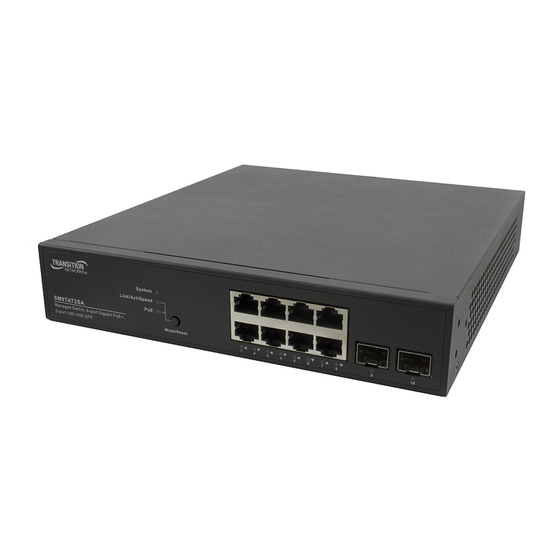
The SMxTAT2SA delivers 8/16/24 (10M/100M/1G) RJ45 ports with 8 PoE+ ports (supports 802.3 at/af, and total up to 130W on the SM8TAT2SA) and 2 GbE SFP ports. SMxTAT2SA provides high hardware performance and environment flexibility for SMBs and Enterprises. The embedded Device Managed System (DMS) feature makes the switch easy to use, configure, install, and troubleshoot in video surveillance, wireless access, and other SMB and Enterprise applications. - Page 7 Library (no logon required). Note that this manual provides links to third party web sites for which Transition Networks is not responsible. This manual describes how to install, configure, and troubleshoot the SMxTAT2SA switch. Other related manuals are listed below.
-
Page 8: Chapter 1 - Web-Based Management
Chapter 1 - Web-based Management Initial Configuration This chapter describes how to configure and manage the SMxTAT2SA via the web user interface. With this facility, you can easily access and monitor through any one port of the switch all the status of the switch, including each port activity, Spanning tree status, port aggregation status, multicast traffic, VLAN and priority status, even illegal access. - Page 9 Figure 1: The Login page 33717 Rev. A https://www.transition.com Page 9 of 248...
-
Page 10: Chapter 2 - First Time Wizard
Chapter 2 - First Time Wizard The first time you use this device you can configure some basic settings, such as password, IP address, date and time, and system information. Use the following procedure: Step 1: Change default password Enter a new password and then enter it again. Click the Next button. Figure 2-1: Change default password Step 2: Set IP address Select “Obtain IP address via DHCP”... - Page 11 Step 3: Set date and time Enable “Automatic data and time” or select manually to set date and time. Click the Next button. Figure 2-3: Set date and time Step 4: Set system information You can set some system information to this device, such as “System contact”, “System name”, “System location”.
- Page 12 Menu Bar Overview Click the Transition Networks logo to return to the Switch > System > System Information page. Click the icon to toggle between the current menu path and the previous one. Hover the cursor over any port to see its current status: Click on any port to display its current Detailed Port Statistics page.
-
Page 13: Chapter 3 - System
Figure 3-1: System Information (SM8TAT2SA shown) Parameter descriptions: Model Name: the specific switch model number (i.e., SM8TAT2SA, SM16TAT2SA, or SM24TAT2SA). System Description: e.g., Smart Managed Switch, 16-port Gigabit PoE+, 2-port 100/1000 SFP. Hardware Version: e.g., v1.00. Mechanical Version: e.g., v1.00. - Page 14 length is 0 to 128, and the allowed content is an ASCII character from 32 to 126. Contact: The textual identification of the contact person for this managed node, with information on how to contact this person. The allowed string length is 0 to 128, and the allowed content is ASCII characters from 32 to 126.
-
Page 15: Ip Addres
3-2 IP Address 3-2.1 IP Settings At System > IP Address > IP Settings you can configure the IPv4 address and related parameters. Web Interface To configure IP settings in the web interface: 1. Click System, IP Address, IP Settings. 2. -
Page 16: Advanced Ip Settings
3-2.1 Advanced IP Settings The IPv4 address for the switch can be obtained via DHCP Server for VLAN 1. To manually configure an address, you must change the switch's default settings to values that are compatible with your network. You may also need to establish a default gateway between the switch and management stations that exist on another network segment. - Page 17 DHCPv4 Fallback: The number of seconds for trying to obtain a DHCP lease. After this Timeout period expires, a configured IPv4 address will be used as IPv4 interface address. A value of zero disables the fallback mechanism, such that DHCP will keep retrying until a valid lease is obtained. Legal values are 0 to 4294967295 seconds.
-
Page 18: Ip Status
3-2.2 IP Status This page displays the status of the IP protocol layer. The status is defined by the IP interfaces, the IP routes and the neighbor cache (ARP cache) status. Web Interface To display the log configuration in the web interface: Click System, IP Address, and Status. -
Page 19: Dns Server
Interface: Shows the name of the interface (e.g., OS:lo or VLAN1). Neighbor Cache IP Address: Show the IP address of the entry (e.g., 192.168.1.99). Link Address: Show the Link (MAC) address for which a binding to the given IP address exists (e.g., VLAN1:00-1b-11-b2-6d-4b). -
Page 20: Time Configuration
3-3 System Time The switch provides manual and automatic ways to set the system time via NTP. For manual setting, enter the “Year”, “Month”, “Day”, “Hour” and “Minute” within the valid value range indicated for each item. Web Interface To configure Time in the web interface: 1. - Page 21 Daylight Saving Time Configuration Daylight Saving Time: This is used to set the clock forward or backward according to the configurations set below for a defined Daylight Saving Time duration. Select 'Disable' to disable the Daylight Saving Time configuration. Select 'Recurring' and configure the Daylight Saving Time duration to repeat the configuration every year.
- Page 22 Configure NTP Server: At “Clock Source” select NTP Server. Click the Configure NTP Server button to configure NTP server. Figure 3-3: The NTP Configuration page NTP (Network Time Protocol) is used to sync the network time based Greenwich Mean Time (GMT). If use the NTP mode and select a built-in NTP time server or manually specify an user-defined NTP server as well as Time Zone, the switch will sync the time in a short after pressing Apply button.
-
Page 23: Syslog Configuration
3-4 System Log 3-4.1 Syslog Configuration Syslog is a standard for logging program messages. It allows separation of the software that generates messages from the system that stores them and the software that reports and analyzes them. It can be used as well a generalized informational, analysis and debugging messages. -
Page 24: View Log
3-4.2 View Log This page displays the switch system log (Syslog) information. Web Interface To display the log configuration in the web interface: Click System, Log, and View Log. View the log information. Figure 3-4.2: The System Log Information page Parameter descriptions: ID: ID (>= 1) of the system log entry. - Page 25 Buttons Refresh: Updates the system log entries, starting from the current entry ID. Clear Logs: Clears all the system log entries and display “No data available in table”. Next: Updates the system log entries, turn to the next page. Previous: Updates the system log entries, turn to the previous page. System Log Message Examples LINK-UPDOWN: Interface GigabitEthernet 1/1, changed state to up.
-
Page 26: Lldp
3-5 LLDP The switch supports the LLDP. For current information on your switch model, The Link Layer Discovery Protocol (LLDP) provides a standards-based method for enabling switches to advertise themselves to adjacent devices and to learn about adjacent LLDP devices. LLDP is a vendor-neutral Link Layer protocol in the Internet Protocol Suite used by network devices for advertising their identity, capabilities, and neighbors on a IEEE 802 local area network, principally wired Ethernet. - Page 27 Tx Hold: Each LLDP frame contains information about how long the information in the LLDP frame will be considered valid. The LLDP information valid period is set to Tx Hold multiplied by Tx Interval seconds. Valid values are 2 - 10 times. The default is 4 times. Tx Delay: If some configuration is changed (e.g.
- Page 28 Sys Name: Optional TLV: When checked the "system name" is included in LLDP information transmitted. Sys Descr: Optional TLV: When checked the "system description" is included in LLDP information transmitted. Sys Capa: Optional TLV: When checked the "system capability" is included in LLDP information transmitted.
-
Page 29: Lldp-Med Configuration
3-5.2 LLDP-MED Configuration Media Endpoint Discovery is an enhancement of LLDP, known as LLDP-MED that provides these facilities: Auto-discovery of LAN policies (such as VLAN, Layer 2 Priority and Differentiated services (Diffserv) settings) enabling plug and play networking. Device location discovery allows creation of location databases and, in the case of Voice over Internet Protocol (VoIP), Enhanced 911 services. - Page 30 Parameter descriptions: Fast start repeat count Rapid startup and Emergency Call Service Location Identification Discovery of endpoints is a critically important aspect of VoIP systems in general. In addition, it is best to advertise only those pieces of information which are specifically relevant to particular endpoint types (for example only advertise the voice network policy to permitted voice-capable devices), both in order to conserve the limited LLDPU space and to reduce security and system integrity issues that can come with inappropriate knowledge of the network policy.
- Page 31 Civic Address Location: IETF Geopriv Civic Address based Location Configuration Information (Civic Address LCI). Country code: The two-letter ISO 3166 country code in capital ASCII letters - Example: DK, DE or US. State: National subdivisions (state, canton, region, province, prefecture). County: County, parish, gun (Japan), district.
- Page 32 The network policy attributes advertised are: 1. Layer 2 VLAN ID (IEEE 802.1Q-2003) 2. Layer 2 priority value (IEEE 802.1D-2004) 3. Layer 3 Diffserv code point (DSCP) value (IETF RFC 2474) This network policy is potentially advertised and associated with multiple sets of application types supported on a given port.
- Page 33 Tag : Tag indicating whether the specified application type is using a 'tagged' or an 'untagged' VLAN. Untagged indicates that the device is using an untagged frame format and as such does not include a tag header as defined by IEEE 802.1Q-2003. In this case, both the VLAN ID and the Layer 2 priority fields are ignored and only the DSCP value has relevance.
-
Page 34: Lldp Neighbor
3-5.3 LLDP Neighbor This page provides a status overview for all LLDP neighbors. The displayed table contains a row for each port on which an LLDP neighbor is detected. Web Interface To show LLDP neighbors: 1. Click System, LLDP, and LLDP Neighbor. 2. - Page 35 layer entities to assist discovery by the network management. This could for instance hold the neighbor's IP address. Buttons Auto-refresh: Check to refresh the page automatically every seconds. Refresh: Click to refresh the page immediately.
-
Page 36: Lldp-Med Neighbor
3-5.4 LLDP-MED Neighbor This page provides a status overview of all LLDP-MED neighbors. The displayed table contains a row for each port on which an LLDP neighbor is detected. This function applies to VoIP devices which support LLDP-MED. Web Interface To show LLDP-MED neighbor: 1. - Page 37 LLDP-MED Endpoint Device Definition: LLDP-MED Endpoint Devices, as defined in TIA-1057, are located at the IEEE 802 LAN network edge, and participate in IP communication service using the LLDP-MED framework. Within the LLDP-MED Endpoint Device category, the LLDP-MED scheme is broken into further Endpoint Device Classes, as defined in the following.
- Page 38 Application Type: Indicates the primary function of the application(s) defined for this network policy, advertised by an Endpoint or Network Connectivity Device. The possible application types are: 1. Voice - for use by dedicated IP Telephony handsets and other similar appliances supporting interactive voice services.
- Page 39 Buttons Auto-refresh: Check to refresh the page automatically every seconds. Refresh: Click to refresh the page immediately.
-
Page 40: Lldp Statistics
3-5.5 LLDP Statistics Two types of counters are shown. Global counters are counters that refer to the whole switch, while Local counters refer to per port counters for the switch. Web Interface To show LLDP Statistics: 1. Click System, LLDP, and LLDP Statistics. 2. - Page 41 Rx Frames: The number of LLDP frames received on the port. Rx Errors: The number of received LLDP frames containing some kind of error. Frames Discarded: If an LLDP frame is received on a port, and the switch's internal table has run full, the LLDP frame is counted and discarded.
-
Page 42: Upnp
3-6 UPnP The goals of UPnP (Universal Plug and Play) are to allow devices to connect seamlessly and to simplify the implementation of networks in the home (data sharing, communications, and entertainment) and in corporate environments for simplified installation of computer components. -
Page 43: Chapter 4 - Port Management
Chapter 4 - Port Management This page lets you configure the Port parameters of the switch, and enable or disable a switch Port. You can also monitor the ports’ speed and flow control status here. 4-1 Port Configuration This page displays current port configurations. Ports can also be configured here. Web Interface To configure a current Port Configuration in the web interface: 1. - Page 44 SFP_Auto_AMS - Automatically determines the speed of the SFP. Note: There is no standardized way to do SFP auto detect, so here it is done by reading the SFP rom. Due to the missing standardized way of doing SFP auto detect some SFPs might not be detectable. The port is set in AMS mode.
-
Page 45: P Ort S Tatistics
4-2 Port Statistics The section describes the Port statistics information and provides an overview of general traffic statistics for all switch ports. Web Interface To Display the Port Statistics Overview in the web interface: 1. Click Port Management and Port Statistics. 2. - Page 46 Click a linked port to see its detailed port statistics. The displayed counters are the totals for receive and transmit, the size counters for receive and transmit, and the error counters for receive and transmit. Figure 4-2: The Detailed Port Statistics page Parameter descriptions: Upper left scroll bar: To scroll which port to display the Port statistics with “Port-1”, “Port-2”, ...
- Page 47 Receive Error Counters Rx Drops: The number of frames dropped due to lack of receive buffers or egress congestion. Rx CRC/Alignment: The number of frames received with CRC or alignment errors. Rx Undersize: The number of short 1 frames received with valid CRC. Rx Oversize: The number of long 2 frames received with valid CRC.
-
Page 48: Sfp Port Info
4-3 SFP Port Info This section describes the SFP module detail information when connected to the switch. The information includes Connector type, Fiber type, wavelength, bit rate, Vendor OUI, etc. Web Interface To Display the SFP information in the web interface: 1. - Page 49 Date Code: Shows the date this SFP module was made. Temperature: Shows the current temperature of SFP module. Vcc: Shows the working DC voltage of SFP module. Mon1(Bias) mA: Shows the Bias current of SFP module in milliamps. Mon2(TX PWR): Shows the transmit power of SFP module in dBm. Mon3(RX PWR): Shows the receiver power of SFP module in dBm.
-
Page 50: E Nergy E Fficient E Thernet
4-4 Energy Efficient Ethernet This page lets you inspect and configure the current EEE port settings. EEE (Energy Efficient Ethernet) is defined in IEEE 802.3az as a power saving option that reduces the power usage when there is very low traffic utilization (or no traffic). EEE works by powering down circuits when there is no traffic. -
Page 51: Link Aggregation
4-5 Link Aggregation 4-5.1 Port This section describes Port setting/status used to configure the trunk property of each port. Web Interface To configure the trunk property of each and every port in the web interface: Click Port Management, Link Aggregation, and port. Specify the Method, Group, LACP Role and LACP Timeout. - Page 52 LACP Timeout: The Timeout controls the period between BPDU transmissions. Fast: It will transmit LACP packets each second, Slow: It will wait for 30 seconds before sending a LACP packet. Aggtr: Aggtr is an abbreviation of “aggregator”. Every port is also an aggregator, and its own aggregator ID is the same as its own Port No.
-
Page 53: Aggregator View
4-5.2 Aggregator View To display the current port trunking information from the aggregator point of view. Web Interface To see the LACP detail in the web interface: Click Port Management, Link Aggregation, and Aggregator View. Click the Lacp Detail radio button. Figure 4-5.2: The Aggregator View page Parameter descriptions: Aggregator: Shows the aggregator ID of every port. - Page 54 Buttons Lacp Detail: Click this button to display the aggregator information, as described below. Figure 4-5.2: The LACP Detail page Parameter descriptions: Actor System Priority: Show the System Priority part of the aggregation Actor. (1-65535). Mac Address: The system ID of the aggregation Actor. Actor Port: The actor's port number connected to this port.
-
Page 55: Aggregation Hash Mode
4-5.3 Aggregation Hash Mode Web Interface hash mode in the web interface: To configure the Aggregation Click Port Management, Link Aggregation, and Aggregation Hash Mode. Click Hash Code Contributors to select the mode. Click the Apply button to save the setting. To cancel the setting, click the Reset button to previously saved values. -
Page 56: Lacp System Priority
4-5.4 LACP System Priority This page lets you set the priority part of the LACP system ID. LACP will only aggregate together the ports whose peer link partners are all on a single system. Each system that supports LACP will be assigned a globally unique System Identifier for this purpose. A system ID is a 64-bit field comprising a 48-bit MAC Address and 16-bit priority value. -
Page 57: Loop Protection
4-6 Loop Protection 4-6.1 Configuration Loop Protection is used to detect the presence of traffic. When the switch receives packet’s (looping detection frame) MAC address the same as oneself from port, Loop Protection is shown. The port will be locked when it receives the looping Protection frames. If you want to resume the locked port, find and remove the looping path, then select resume the locked port and click on “Resume”... - Page 58 Action: Configures the action performed when a loop is detected on a port. Valid values are Shutdown Port, Shutdown Port and Log, or Log Only. Tx Mode: Controls whether the port is actively generating loop protection PDUs, or whether it is just passively looking for looped PDUs.
-
Page 59: Status
4-6.2 Status This section displays the loop protection port status. Web Interface To display the Loop Protection status in the web interface: 1. Click Port Management, Loop Protection, and Status. 2. To automatically refresh the information select “Auto refresh”. 3. Click “Refresh” to refresh the Loop Protection Status. Figure 4-6.2: Loop Protection Status Parameter descriptions: Port: The switch port number of the logical port. -
Page 60: Poe Configuration
Chapter 5 - PoE Management PoE (Power over Ethernet) is used to transmit electrical power to remote devices over standard Ethernet cable. PoE can be used for powering IP telephones, wireless LAN access points and other equipment, where it would be difficult or expensive to connect the equipment to main power supply. - Page 61 Reserved Power determined by: Radio button to select one of two modes for configuring how the ports/PDs may reserve power: Class: The PD will negotiate PD class then feed power if the PD request power is comply with standard. If Maximum Power at the port is configured different then factory default value 30W, the PD connects the port again;...
- Page 62 5-2 PoE Status This page lets you view the current status of all PoE ports. Web Interface To display PoE Status in the web interface: Click PoE Management and PoE Status. Scroll “Auto-refresh” to on or off. Click “Refresh” to refresh the port detailed statistics. Figure 5-2: PoE Status Parameter descriptions: Local Port: The logical port number for this row.
- Page 63 Power Override: Displays 0 (override disabled) or 1 (override the default power requirement specified by the IEEE classification). The difference between the power requirement mandated by the IEEE classification and what is actually needed by the PD is returned into the global power budget for use by additional PDs.
- Page 64 Five PD Classes are defined by the IEEE standards: Classification Class Class Usage Power Range [W] Current [mA] Description Classification Default 0–4 0.44–12.94 unimplemented Optional 9–12 0.44–3.84 Very Low power Optional 17–20 3.84–6.49 Low power Optional 26–30 6.49–12.95 Mid power Valid for 802.3at (Type 2) devices, not 36–44 12.95–25.50...
-
Page 65: Poe Power Delay
5-3 PoE Power Delay This page lets you specify how much time the switch will wait before it provides power to a specified port after the switch reboots. Web Interface To configure Power over Ethernet Power Delay in the web interface: Click PoE Management and PoE Power Delay. -
Page 66: Poe Auto Power Reset
5-4 PoE Auto Power Reset This page lets you specify the auto detection parameters to check the link status between PoE ports and PDs. When it detects a failed connection, it will reboot the remote PD automatically. Web Interface To configure Power over Ethernet Auto Power Reset in the web interface: Click PoE Management and PoE Auto Power Reset. - Page 67 Buttons Apply : Click to save changes. Reset : Click to undo any changes made locally and revert to previously saved values.
- Page 68 5-5 PoE Scheduling Profile This page lets you define the profile for PoE scheduling. Figure 5-5: PoE Scheduling Profile Parameters: Profile: The index of profile. You can configure up to 16 profiles. Name: The name of profile. The default name is "Profile 1". You can define the name for identifying the profile.
-
Page 69: Chapter 6 - Vlan Management
Chapter 6 - VLAN Management 6-1 VLAN Configuration This page lets you assign a specific VLAN for management purpose. The management VLAN is used to establish an IP connection to the switch from a workstation connected to a port in the VLAN. This connection supports a VSM, SNMP, and Telnet session. By default, the active management VLAN is VLAN 1, but you can designate any VLAN as the management VLAN using the Management VLAN window. - Page 70 question. Grayed out fields show the value that the port will get when the mode is applied. Access: Access ports are normally used to connect to end stations. Dynamic features like Voice VLAN may add the port to more VLANs behind the scenes. Access ports have these characteristics: •...
- Page 71 that it is not a member of. VLAN Trunking: Trunk and Hybrid ports allow for enabling VLAN trunking. When VLAN trunking is enabled, frames classified to unknown VLANs are accepted on the port whether ingress filtering is enabled. This is useful in scenarios where a cloud of intermediary switches must bridge VLANs that haven't been created.
-
Page 72: Vlan Membership
DMS: Transition Networks’ DMS (Device Management System) is an intelligent management tool embedded in the switch to intuitively help reducing support time, cost, and effort. - Page 73 Port Members: A row of check boxes for each port is displayed for each VLAN ID. If a port is included in a VLAN, an image will be displayed. If a port is included in a Forbidden port list, an image will be displayed.
- Page 74 DMS: Transition Networks’ DMS (Device Management System) is an intelligent management tool embedded in the switch to intuitively help reduce support time, cost, and effort.
- Page 75 Port Type: Shows the Port Type. Port type can be any of Unaware, C-port, S-port, Custom S-port. If Port Type is Unaware, all frames are classified to the Port VLAN ID and tags are not removed. C-port is Customer Port. S-port is Service port. Custom S-port is S-port with Custom TPID. Ingress Filtering: Shows the ingress filtering on a port.
- Page 76 6-4 VLAN Selective QinQ Navigate to Switch > VLAN Management > VLAN Selective QinQ to create new and edit existing entries. Parameter descriptions: Delete: To delete a private VLAN entry, check this box. The entry will be deleted during the next apply. CVID (Customer VLAN ID): the inner VLAN tag id of the IEEE 802.1ad frame.
-
Page 77: Mac- Based Vlan
6-5 MAC-based VLAN Navigate to Switch > VLAN Management > MAC-based VLAN > Configuration to configure new entries and view the status of existing entries. 6-5.1 Configuration Parameter descriptions: Delete: To delete a private VLAN entry, check this box. The entry will be deleted during the next apply. MAC Address: Enter the MAC address for the entry. - Page 78 6-5.2 Status Navigate to Switch > VLAN Management > MAC-based VLAN > Status to view existing members’ status. Parameter descriptions: MAC Address: Displays the MAC address for the entry. VLAN ID: Displays the VLAN ID (VID) for the entry. User: Displays User Type for the entry (Combined, Admin, NAS, GVRP, MVR, Voice, VLAN, MSTP, DMS, or VCL).
-
Page 79: P Rotocol - Based Vlan
6-6 Protocol-based VLAN 6-6.1 Protocol to Group Mapping Table Navigate to Switch > VLAN Management > Protocol-based VLAN > Protocol to Group to display the Protocol to Group Mapping Table. Here you can add new entries and view or edit existing table entries. Parameter descriptions: Delete: To delete an entry, check this box. - Page 80 6-6.2 Group Name to VLAN mapping Table Navigate to Switch > VLAN Management > Protocol-based VLAN > Group to VLAN to display the Group Name to VLAN mapping Table. Add new entries and view or edit existing table entries. Parameter descriptions: Delete: To delete a private VLAN entry, check this box.
- Page 81 6-7 IP Subnet-based VLAN Navigate to Switch > VLAN Management > Protocol-based VLAN > IP Subnet-based VLAN to display the IP Subnet-based VLAN Membership Configuration table. Here you can add new entries and view or edit existing table entries. Parameter descriptions: Delete: To delete an entry, check this box.
-
Page 82: P Rivate Vlan
6-8 Private VLAN The Private VLAN membership configurations for the switch can be monitored and modified here. Private VLANs can be added or deleted here. Port members of each Private VLAN can be added or removed here. Private VLANs are based on the source port mask, and there are no connections to VLANs. This means that VLAN IDs and Private VLAN IDs can be identical. -
Page 83: Port Isolation
6-9 Port Isolation Port Isolation provides for an apparatus and method to isolate ports on layer 2 switches on the same VLAN to restrict traffic flow. The apparatus comprises a switch having said plurality of ports, each port configured as a protected port or a non-protected port. An address table memory stores an address table having a destination address and port number pair. -
Page 84: V Oice Vlan
6-10 Voice VLAN The Voice VLAN feature enables voice traffic forwarding on the Voice VLAN, then the switch can classify and schedule network traffic. It is recommended that there be two VLANs on a port - one for voice, one for data. - Page 85 Port Members: Indicates the Voice VLAN port mode operation. You must disable the MSTP feature before you enable Voice VLAN. It can avoid the conflict of ingress filtering. Select which port that you want to enable the Voice VLAN mode operation. Port Configuration Port: The switch port number of the Voice VLAN port.
- Page 86 6-6.1 Voice VLAN OUI Configuration Table The section describes how to configure the Voice VLAN OUI table. The maximum entry number is 16. Modifying the OUI table will restart auto detection of the OUI process. An Organizationally Unique Identifier (OUI) is a 24-bit number that uniquely identifies a vendor, manufacturer, or other organization.
-
Page 87: Global Settings
Chapter 7 - Quality of Service 7-1 Global Settings Use the QoS Global Settings page to set the trust behavior for QoS basic mode. This configuration is active when the switch is in QoS basic mode. Packets entering a QoS domain are classified at the edge of the QoS domain. Web Interface To configure the Global Settings in the web interface: 1. -
Page 88: Port Settings
7-2 Port Settings Web Interface To configure the QoS Port Setting in the web interface: 1. Click Quality of Service and Port Settings. 2. Select Mode, Default CoS, and Source CoS, for each port. 3. Check which port(s) on which you want to enable the Remark Cos, Remark DSCP, and Remark IP Precedence. - Page 89 Apply : Click to save changes. Reset : Click to undo any changes made locally and revert to previously saved values.
-
Page 90: Port Policing
7-3 Port Policing This section provides an overview of QoS Ingress Port Policers for all switch ports. Port Policing is useful in constraining traffic flows and marking frames above specific rates. Policing is primarily useful for data flows and voice or video flows because voice and video usually maintains a steady rate of traffic. - Page 91 7-4 Port Shaper This section provides an overview of QoS Egress Port Shapers for all switch ports. Web Interface To configure the QoS Port Shapers in the web interface: 1. Click Quality of Service and Port Shaper. 2. Select the port to configure QoS Egress Port Shaper. 3.
- Page 92 Apply : Click to save changes. Reset : Click to undo any changes made locally and revert to previously saved values.
-
Page 93: Storm Control
7-5 Storm Control The section allows user to configure the Storm control for the switch. There is a destination lookup failure storm rate control, multicast storm rate control, and a broadcast storm rate control. These only affect flooded frames, i.e. frames with a (VLAN ID, DMAC) pair not present on the MAC Address table. -
Page 94: P Ort S Cheduler
7-6 Port Scheduler This section provides an overview of QoS Egress Port Scheduler for all switch ports. Web Interface To configure the QoS Port Schedulers in the web interface: 1. Click Quality of Service and Port Scheduler. 2. Select Scheduler Mode for each port. 3. -
Page 95: Co/802.1P Mapping
7-7 CoS/802.1p Mapping Use the CoS/802.1p to Queue page to map 802.1p priorities to egress queues. The CoS/802.1p to Queue table determines the egress queues of the incoming packets based on the 802.1p priority in their VLAN tags. For incoming untagged packets, the 802.1p priority will be the default CoS/802.1p priority assigned to the ingress ports. -
Page 96: C O S/802.1 P R Emarking
7-8 CoS/802.1p Remarking Use the Queues to CoS/802.1p page to remark the CoS/802.1p priority for egress traffic from each queue. Web Interface To configure the Cos/802.1p Remarking in the web interface: 1. Click Quality of Service and Cos/802.1p Remarking. 2. Select CoS/802.1p. 3. -
Page 97: Ip P Recedence M Apping
7-9 IP Precedence Mapping This page lets you map an IP precedence to an egress queue. Web Interface To configure the IP Precedence Mapping in the web interface: 1. Click Quality of Service and IP Precedence Mapping. 2. Select Queue ID. 3. -
Page 98: Ip P Recedence R Emarking
7-10 IP Precedence Remarking This page lets you map egress queue to IP precedence. Web Interface To configure the IP Precedence Remarking in the web interface: 1. Click Quality of Service and IP Precedence Remarking. 2. Select IP Precedence. 3. Click the Apply button to save the setting. 4. -
Page 99: Dscp M Apping
7-11 DSCP Mapping Use the DSCP to Queue page to map IP DSCP to egress queues. The DSCP to Queue table determines the egress queues of the incoming IP packets based on their DSCP values. The original VLAN Priority Tag (VPT) of the packet is unchanged. It is possible to achieve the desired QoS in a network by simply changing the DSCP to Queue mapping, the queue schedule method, and bandwidth allocation. -
Page 100: Dscp R Emarking
7-12 DSCP Remarking Use the Queues to DSCP page to remark DSCP value for egress traffic from each queue. Web Interface To configure the DSCP Remarking in the web interface: 1. Click Quality of Service and DSCP Remarking. 2. Select DSCP. 3. -
Page 101: Chapter 8 - Spanning Tree
Chapter 8 - Spanning Tree The Spanning Tree Protocol (STP) can be used to detect and disable network loops, and to provide backup links between switches, bridges or routers. This allows the switch to interact with other bridging devices (that is, an STP-compliant switch, bridge or router) in your network to ensure that only one route exists between any two stations on the network, and provide backup links which automatically take over when a primary link goes down. - Page 102 8-1 State The page lets you enable or disable MSTP; you can also select what protocol version you want. The default is Spanning Tree enabled. Web Interface To configure the Spanning Tree Protocol version in the web interface: 1. Click Spanning Tree and state. 2.
-
Page 103: Region Config
8-2 Region Config The section describes how to configure the basic identification of a MSTP bridge. Bridges participating in a common MST region must have the same Region Name and Revision Level. Web Interface To configure the Region Config in the web interface: Click Spanning Tree and Region Config. -
Page 104: Instance View
8-3 Instance View The section providing an MST instance table which include information(VLAN membership of a MSTI ) of all spanning instances provisioned in the particular MST region which the bridge belongs to. Through this table, additional MSTP configuration data can be applied and MSTP status can be retrieved. - Page 105 Please refer to the Add Vlan introduction: Parameter descriptions: Instance ID: The Range is 1-4094. Vlan Mapping: The list of VLANs mapped to the MSTI. The VLANs can be given as a single (xx, xx being between 1 and 4094) VLAN, or a range (xx-yy), each of which must be separated with comma and/or space.
- Page 106 Apply : Click to save changes. Reset : Click to undo any changes made locally and revert to previously saved values. Back : Click to undo any changes made locally and return to the Users. Port Config of Instance 0 : Figure 8-3: Port Config of Instance 0 Parameter descriptions: Port: The logical port for the settings contained in the same row.
- Page 107 Figure 8-3: Instance Status of Instance 0 Parameter descriptions: MSTP State : MSTP protocol is Enable or Disable. Force Version : Shows the current spanning tree protocol version configured. Bridge Max Age : Shows the Max Age setting of the bridge itself. Bridge Forward Delay : Shows the Forward Delay setting of the bridge itself.
- Page 108 TIME SINCE LAST TOPOLOGY CHANGE(SECs) : Time Since Last Topology Change is the elapsed time in unit of seconds for a bunch of “Topology Change and(or) Topology Change Notification receiving” to occur. When new series of Topology Changes occur again, this counter will be reset to 0. TOPOLOGY CHANGE COUNT(SECs) : The per spanning tree instance Topology Change Count expresses the time spent in unit of seconds since the beginning of the Spanning Tree Topology Change to the end of the STP convergence.
- Page 109 Port Status of Instance 0 : Figure 8-3: Port Status of Instance 0 Parameter descriptions: Port No: The port number to which the configuration applies. Status: The forwarding status. Same definition as of the RSTP specification. Possible values are “FORWARDING”, “LEARNING”, “DISCARDING”. Role: The role that a port plays in the spanning tree topology.
-
Page 110: Chapter 9 - Mac Address Tables
Chapter 9 - MAC Address Tables 9-1 Configuration Switching of frames is based on the DMAC address contained in the frame. The switch builds up a table that maps MAC addresses to switch ports for knowing which ports the frames should go to (based upon the DMAC address in the frame). - Page 111 Parameter descriptions: Aging Configuration: By default, dynamic entries are removed from the MAC table after 300 seconds. This removal is also called aging. Configure aging time by entering a value here in seconds. The valid range is 10 - 1000000 seconds. Disable the automatic aging of dynamic entries by checking Disable automatic aging.
-
Page 112: I Nformation
9-2 Information Entries in the MAC Table are shown on this page. The MAC Table contains up to 8192 entries, and is sorted first by VLAN ID, then by MAC address. Web Interface To display the Dynamic MAC Table in the web interface: 1. -
Page 113: Igmp Snooping
Chapter 10 - Multicast 10-1 IGMP Snooping This function is used to establish the multicast groups to forward the multicast packet to the member ports, and, in nature, avoids wasting the bandwidth while IP multicast packets are running over the network. This is because a switch that does not support IGMP or IGMP Snooping cannot tell a multicast packet from a broadcast packet, so it can only treat them all as a broadcast packet. - Page 114 Figure 10-1.1: IGMP Snooping Configuration Parameter descriptions: Global Configuration Snooping Enabled: Enable the Global IGMP Snooping. Unregistered IPMCv4 Flooding enabled: Enable unregistered IPMCv4 traffic flooding. IGMP SSM Range: SSM (Source-Specific Multicast) Range lets the SSM-aware hosts and routers run the SSM service model for the groups in the address range. Format: (IP address/ sub mask). Per IETF 4607, IP version 4 (IPv4) addresses in the 232/8 (232.0.0.0 to232.255.255.255) range are designated as source-specific multicast (SSM) destination addresses and are reserved for use by...
-
Page 115: Vlan Configuration
10-1.2 VLAN Configuration The section describes the VLAN configuration setting process integrated with IGMP Snooping function. Each page shows up to 99 entries from the VLAN table, default being 20, selected through the "entries per page" input field. When first visited, the web page will show the first 20 entries from the beginning of the VLAN Table. - Page 116 network. The allowed range is 1 to 255; default RV value is 2. QI(sec): Query Interval. The Query Interval is the interval between General Queries sent by the Querier. The allowed range is 1 to 31744 seconds; default query interval is 125 seconds. QRI(0.1 sec): Query Response Interval.
-
Page 117: Status
10-1.3 Status After you complete the IGMP Snooping configuration, you can view the IGMP Snooping Status. This page displays the IGMP Snooping detail status. Web Interface To display the IGMP Snooping status in the web interface: 1. Click Multicast, IGMP Snooping, and Status. 2. - Page 118 Router Port: Displays which ports act as router ports. A router port is a port on the Ethernet switch that leads towards the Layer 3 multicast device or IGMP querier. Static denotes the specific port is configured to be a router port. Dynamic denotes the specific port is learnt to be a router port. Both denote the specific port is configured or learnt to be a router port.
-
Page 119: Group Information
10-1.4 Group Information After you complete setting the IGMP Snooping function, you can view the IGMP Snooping Group Information. Entries in the IGMP Group Table are shown on this page. The IGMP Group Table is sorted first by VLAN ID, and then by group. When the end is reached the text "No more entries"... -
Page 120: Igmp Sfm Information
10-1.5 IGMP SFM Information Entries in the IGMP SFM Information Table are shown on this page. The IGMP SFM (Source-Filtered Multicast) Information Table also contains the SSM (Source-Specific Multicast) information. This table is sorted first by VLAN ID, then by group, and then by Port. Different source addresses belong to the same group are treated as single entry. - Page 121 Buttons Auto-refresh : Check this box to refresh the page automatically every 3 seconds. Refresh : Click to refresh the page immediately. Next : Updates the system log entries, turn to the next page. Previous : Updates the system log entries, turn to the previous page.
-
Page 122: Mld Snooping
10-2 MLD Snooping Curiously enough, a network node that acts as a source of IPv6 multicast traffic is only an indirect participant in MLD snooping - it just provides multicast traffic, and MLD doesn’t interact with it. (Note, however, that in an application like desktop conferencing a network node may act as both a source and an MLD host;... - Page 123 Figure 10-2.1: MLD Snooping Basic Configuration Parameter descriptions: Global Configuration Snooping Enabled : Enable the Global MLD Snooping. Unregistered IPMCv6 Flooding enabled : Enable unregistered IPMCv6 traffic flooding. Flooding control takes effect only when MLD Snooping is enabled. When MLD Snooping is disabled, then unregistered IPMCv6 traffic flooding is always active in spite of this setting.
-
Page 124: Vlan Configuration
10-2.2 VLAN Configuration When MLD snooping is enabled on a VLAN, the switch acts to minimize unnecessary multicast traffic. If the switch receives multicast traffic destined for a given multicast address, it forwards that traffic only to ports on the VLAN that have MLD hosts for that address. It drops that traffic for ports on the VLAN that have no MLD hosts The will use the last entry of the currently displayed entry as a basis for the next lookup. - Page 125 LLQI (LMQI for IGMP): Last Member Query Interval. The Last Member Query Time is the time value represented by the Last Member Query Interval, multiplied by the Last Member Query Count. The allowed range is 0 to 31744 in tenths of seconds; default last member query interval is 10 in tenths of seconds (1 second).
-
Page 126: Status
10-2.3 Status The section describes when you complete the MLD Snooping and how to display the MLD Snooping Status and detail information. It will help you to find out the detail information of MLD Snooping status. Web Interface To display the MLD Snooping Status in the web interface: 1. -
Page 127: Groups Information
10-2.4 Groups Information The section describes user could set the MLD Snooping Groups Information. The "Start from VLAN", and "group" input fields allow the user to select the starting point in the MLD Group Table. Web Interface To display the MLD Snooping Group information in the web interface: 1. -
Page 128: Mld Sfm Information
10-2.5 MLD SFM Information Entries in the MLD SFM Information Table are shown on this page. The MLD SFM (Source-Filtered Multicast) Information Table also contains the SSM (Source-Specific Multicast) information. This table is sorted first by VLAN ID, then by group, and then by Port. Different source addresses belong to the same group are treated as single entry. - Page 129 10.3 Multicast Filtering Profile ICMP (Internet Control Message Protocol) generates error response, diagnostic, or routing messages. ICMP messages generally contain information about routing difficulties or simple exchanges such as time-stamp or echo transactions. IGMP Snooping is used to establish the multicast groups to forward the multicast packet to the member ports.
- Page 130 Rule: Click the icon to display the IPMC Profile Rule Settings (In Precedence Order): IPMC Profile Rule parameters: Profile Name: e.g., IPMC-Profile-Cfg-Fisrt_IPMC_ProCfg. Entry Name: Select an existing entry name at the dropdown. Address Range: The allowed range of IP addresses. Action: Select Deny or Permit.
- Page 131 10.3-1 Switch > Multicast > Multicast Filtering Profile > Filtering Address Entry IPMC Profile Table Setting parameters: Delete: Click to delete the entry. The designated entry will be deleted during the next apply. Entry Name: Enter the name of the new profile. Start Address: Enter the beginning IP address of the range.
- Page 132 10.4 MVR Multi VLAN Registration allows switches to automatically discover some of the VLAN information that would otherwise need to be manually configured. The MVR feature enables multicast traffic forwarding on the Multicast VLAN. In a multicast television application, a PC or a television with a set-top box can receive the multicast stream. Multiple set-top boxes or PCs can be connected to one subscriber port, which is a switch port configured as an MVR receiver port.
- Page 133 10.4-2 Switch > MVR > Status The section describes the switch will display the MVR detail Statistics after you had configured MVR on the switch. It provides the detail MVR Statistics Information. MVR Statistics parameters: VLAN ID: Displays the Multicast VID (VLAN ID). IGMP/MLD Queries Received: The number of Received Queries for IGMP and MLD, respectively (e.g., x/y).
- Page 134 10.4-3 Switch > MVR > Group Information The section describes user could display the MVR Groups detail information on the switch. Entries in the MVR Group Table are shown on this page. The MVR Group Table is sorted first by VLAN ID, and then by group.
- Page 135 10.4-4 Switch > MVR > SFM Information The MVR SFM (Source-Filtered Multicast) Information Table also contains the SSM (Source-Specific Multicast) information. This table is sorted first by VLAN ID, then by group, and then by Port. Different source addresses belong to the same group are treated as single entry. Navigating the MVR SFM Information Table Each page shows up to many entries from the MVR SFM Information table, default being 10, selected through the "entries per page"...
-
Page 136: Chapter 11 - Dhcp
Chapter 11 - DHCP This chapter describes how to configure and display the DHCP Snooping parameters of the switch. 11-1 Snooping 11-1.1 Configuration DHCP Snooping is used to block intruder on the untrusted ports of the switch device when it tries to intervene by injecting a bogus DHCP reply packet to a legitimate conversation between the DHCP client and server. - Page 137 Buttons Apply : Click to save changes. Reset : Click to undo any changes made locally and revert to previously saved values.
-
Page 138: Snooping Table
11-1.2 Snooping Table This page displays the dynamic IP assigned information after DHCP Snooping mode is disabled. All DHCP clients obtained the dynamic IP address from the DHCP server will be listed in this table except for local VLAN interface IP addresses. Entries in the Dynamic DHCP Snooping Table are shown on this page. - Page 139 11-1.2 DHCP Detailed Statistics This page provides statistics for DHCP snooping. Notice that the normal forward per-port TX statistics isn't increased if the incoming DHCP packet is done by L3 forwarding mechanism. Also, a clear of the statistics on specific port may not take effect on global statistics since it gathers the different layer overview.
- Page 140 Rx Discarded checksum error: The number of discard packet that IP/UDP checksum is error. Rx Discarded from Untrusted: The number of discarded packet that are coming from untrusted port. Buttons : Use the Port select box to select the port that you want to display the DHCP Detailed Statistics.
- Page 141 11-1.3 DHCP Relay Configuration Navigate to the Switch > DHCP > Relay menu path to display the DHCP Relay Configuration table. Here you can configure the DHCP Relay function. A DHCP relay agent is used to forward and to transfer DHCP messages between the clients and the server when they are not in the same subnet domain.
- Page 142 information mode option operation. The option 82 circuit ID format as "[vlan_id][module_id][port_no]". The first four characters represent the VLAN ID, the fifth and sixth characters are the module ID(in standalone device it always equal 0, in stackable device it means switch ID), and the last two characters are the port number.
- Page 143 11-1.3 DHCP Relay Configuration Navigate to the Switch > DHCP > Relay menu path to display the DHCP Relay Statistics table. This page provides statistics for DHCP relay. Server Statistics Parameters: Transmit to Server: The number of packets that are relayed from client to server. Transmit Error: The number of packets that resulted in error while being relayed from client to server.
- Page 144 11-1.3 DHCP Server Navigate to the Switch > DHCP > Server menu path to display the DHCP Server Configuration table. Here you can add and configure new DHCP servers. Click the Add Interface button to start. This page configures the mode (enable/disable) DHCP server per system and per VLAN, and configures Start IP and End IP addresses.
-
Page 145: Chapter 12 - Security
Chapter 12 - Security This section explains how to configure the switch Security settings. You can use the Security features to restrict input to an interface by limiting and identifying MAC addresses. 12-1 Management 12-1.1 Account This page provides an overview of the current users. Currently the only way to login as another user on the web server is to close and reopen the browser. - Page 146 Buttons Apply: Click to save changes. Reset: Click to undo any changes made locally and revert to previously saved values. Cancel: Click to undo any changes made locally and return to the Users. Delete User: Delete the current user. This button is not available for new configurations (Add New User).
-
Page 147: Privilege Level
12-1.2 Privilege Level The Security > Management > Privilege Level menu path displays the Privilege Level Configuration table. Here you can assign Read-Only or Read-Write privilege levels for each of the major functions. This page provides an overview of the privilege levels. The switch lets you set Group Name Privilege Levels from 0 to 15. -
Page 148: Auth Method
12-1.3 Auth Method The Security > Management > Auth Method menu path displays the Auth Method Configuration tables, where you can configure an authentication method (none, local, or radius) for each client (telnet, ssh, http, https). You can also configure a service port number for telnet, ssh, http, and https clients, and enable the HTTPS Redirect function on this page. - Page 149 tacacs: Use remote TACACS+ server(s) for authentication. Terminal Access Controller Access Control System Plus. It is a networking protocol which provides access control for routers, network access servers and other networked computing devices via one or more centralized servers. TACACS+ provides separate authentication, authorization and accounting services.
-
Page 150: Access Management
12-1.4 Access Management This section shows you how to configure access management table of the Switch including HTTP/HTTPS, SNMP, and TELNET/SSH. You can manage the Switch over an Ethernet LAN or over the Internet. Web Interface To configure an Access Management Configuration in the web interface: Click Security, Management, Access Management. - Page 151 TELNET/SSH: Indicates that the host can access the switch from TELNET/SSH interface if the host IP address matches the IP address range provided in the entry. Note: Firmware v1.01.1209 modified authentication method behavior for telnet/ssh/http/https. The connection is now closed if configuring the first field of Method to "none". Buttons Add New Entry: Click to add a new access management entry.
-
Page 152: Ieee 802.1X
12-2 IEEE 802.1X 12-2.1 Configuration The section describes how to configure the 802.1X parameters of the switch. You can use 802.1X to connect users to a variety of resources including Internet access, conference calls, printing documents on shared printers, or by simply logging on to the Internet. Web Interface To configure the IEEE 802.1X in the web interface: Click Security, IEEE 802.1X, Configuration. -
Page 153: Port Configuration
For MAC-based ports, reauthentication is only useful if the RADIUS server configuration has changed. It does not involve communication between the switch and the client, and therefore doesn't imply that a client is still present on a port (see Aging Period below). Reauthentication Period: Determines the period, in seconds, after which a connected client must be reauthenticated. - Page 154 When authentication is complete, the RADIUS server sends a special packet containing a success or failure indication. Besides forwarding this decision to the supplicant, the switch uses it to open up or block traffic on the switch port connected to the supplicant Suppose two backend servers are enabled and that the server timeout is configured to X seconds (using the AAA configuration page), and suppose that the first server in the list is currently down (but not considered dead).
- Page 155 X Auth/Y Unauth: The port is in a multi-supplicant mode. Currently X clients are authorized and Y are unauthorized. Restart: Two buttons are available for each row. The buttons are only enabled when authentication is globally enabled and the port's Admin State is in an EAPOL-based or MAC-based mode. Clicking these buttons will not cause settings changed on the page to take effect.
-
Page 156: Status
12-2.2 Status The section describes how to show the each port 802.1X status information of the switch. The status includes Admin State, Port State, Last Source, Last ID and Port VLAN ID. Web Interface To displays 802.1X Status in the web interface: Click Security, IEEE 802.1X, Status. - Page 157 Read more about RADIUS-assigned VLANs here. If the port is moved to the Guest VLAN, "(Guest)" is appended to the VLAN ID. Read more about Guest VLANs here. Buttons Auto-refresh: Check to refresh the page automatically every 3 seconds. Refresh: Click to refresh the page immediately. If you select port1 to display 802.1X Statistics: Figure 12-2.2: 802.1X Statistics Port 1 Parameter descriptions:...
-
Page 158: P Ort S Ecurity
12-3 Port Security 12-3.1 Configuration This section shows you how to configure the Port Security settings of the Switch. You can use the Port Security feature to restrict input to an interface by limiting and identifying MAC addresses. Web Interface To configure a Port Security Configuration in the web interface: Click Security, Port Security, Configuration. - Page 159 Limit: The maximum number of MAC addresses that can be secured on this port. This number cannot exceed 1024. If the limit is exceeded, the corresponding action is taken. The switch is "born" with a total number of MAC addresses from which all ports draw whenever a new MAC address is seen on a Port Security-enabled port.
-
Page 160: Status
12-3.2 Status This section shows the Port Security status. Port Security is a module with no direct configuration. Configuration comes indirectly from other modules - the user modules. When a user module has enabled port security on a port, the port is set-up for software-based learning. - Page 161 Buttons Auto-refresh: Check to refresh the page automatically every 3 seconds. Refresh: Click to refresh the page immediately.
-
Page 162: Ip Source Guard
12-3 IP Source Guard The IP Source Guard security feature restricts IP traffic on untrusted Layer 2 ports by filtering traffic based on the DHCP snooping binding database or manually configured IP source bindings. This feature helps prevent IP spoofing attacks. 12-3.1 Configuration Navigate to Security >... - Page 163 12-3.2 Static Table Navigate to Security > IP Source Guard > Static Table to create new Static IP Source Guard entries. Static IP Source Guard Table parameters: Add New Entry: Click the button to add a row for configuring. Port: At the dropdown select the port to be configured. IP Address: Enter the IP address for this new entry.
-
Page 164: Arp Inspection
12-4 ARP Inspection 12-4.1 Port Configuration The Security > ARP Inspection > Port Configuration page displays the Port Mode Configuration table. Parameters: Mode: The global mode setting (on or off). The default is off. Port: A row for each port to be configured. Mode: Check the box if configured. - Page 165 12-4.2 VLAN Configuration The Security > ARP Inspection > VLAN Configuration page displays the VLAN Mode Configuration table. Parameters: Add New Entry: Click the button to add a row for configuring. VLAN ID: The VID for this instance. Log Type: Select None, Deny, Permit, or All. The default is None. Apply: Click the Apply button when done configuring.
- Page 166 12-4.4 Dynamic Table Navigate to the Security > ARP Inspection > Dynamic Table menu path to display the Dynamic ARP Inspection Table. Parameters: Port: Select the port being configured. VLAN ID: The VID for this instance. MAC Address: Enter the MAC address for the entry. IP Address: Enter the IP address for the entry.
- Page 167 12-5 SNMP The Security > SNMP menu path lets you configure SNMP Communities, Groups, Views, and Access and Trap Event Security. 12-5.1 Configuration Security > SNMP > Configuration This section describes how to configure SNMP System on the switch. This function is used to configure SNMP settings, community name, trap host and public traps as well as the throttle of SNMP.
- Page 168 12-5.2 SNMPv3 Security > SNMP > SNMPv3 > Communities The function is used to configure SNMPv3 communities. The Community is unique. To create a new community account, please check <Add New Entry> button, and enter the account information then check the Apply button. You can create up to six Groups. Parameters: Community: Enter the IP address for this new entry.
- Page 169 Security > SNMP > SNMPv3 >Users The function is used to configure SNMPv3 user. The Entry index key is User Name. To create a new User Name account, please check <Add new user> button, and enter the user information then click the Apply button.
- Page 170 Security > SNMP > SNMPv3 > Groups The function is used to configure SNMPv3 group. The Entry index key are Security Model and Security Name. To create a new group account, check the Add New Group button, and enter the group information then click the Apply button.
- Page 171 Security > SNMP > SNMPv3 > Views The function is used to configure SNMPv3 view. The Entry index keys are OID Subtree and View Name. To create a new view account, please check <Add new view> button, and enter the view information then click the Apply button.
- Page 172 Security > SNMP > SNMPv3 > Access The function is used to configure SNMPv3 accesses. The Entry index key are Group Name, Security Model and Security level. To create a new access account, click the Add New Entry button, enter the access information, and then check the Apply button.
- Page 173 Security > SNMP > Trap Event Severity This page displays the Trap Event Severity Configuration table: Parameters: Group Name: Select the name of the existing Group. This is the name identifying the severity group. Severity Level: At the dropdown select Emerg, Alert, Crit, Error, Warning, Notice, Info, or Debug. Every group has an severity level.
-
Page 174: Radius
12-4 RADIUS 12-4.1 Configuration Web Interface To configure a RADIUS in the web interface: Click Security, RADIUS, Configuration. Set Timeout, Retransmit, Deadtime, Key, NAS-IP-Address, NAS IPv6-Address,NAS-Identifier. Click “Add New Entry”. Set Hostname, Auth Port, Acct Port, Timeout, Retransmit, Key. Click the Apply button to save the setting. To cancel the setting, click the Reset button to revert to previously saved values. - Page 175 Key: The secret key - up to 63 characters long - shared between the RADIUS server and the switch. NAS-IP-Address: The IPv4 address to be used as attribute 4 in RADIUS Access-Request packets. If this field is left blank, the IP address of the outgoing interface is used. NAS-IPv6-Address: The IPv6 address to be used as attribute 95 in RADIUS Access-Request packets.
-
Page 176: Status
12-4.2 Status This section shows you an overview/detail of the RADIUS Authentication and Accounting servers’ status to ensure the function is workable. Web Interface To display a RADIUS Status in the web interface: Click Security, RADIUS, and Status. Select a Server line to display the detail statistics for a particular RADIUS server. Figure 12-4.2: RADIUS Server Status Parameter descriptions: RADIUS Authentication Server Status... - Page 177 State : The current state of the server. This field takes one of the following values: Disabled: The server is disabled. Not Ready: The server is enabled, but IP communication is not yet up and running. Ready: The server is enabled, IP communication is up and running, and the RADIUS module is ready to accept accounting attempts.
- Page 178 Access Challenges : The number of RADIUS Access-Challenge packets (valid or invalid) received from the server. Malformed Access Responses : The number of malformed RADIUS Access-Response packets received from the server. Malformed packets include packets with an invalid length. Bad authenticators or Message Authenticator attributes or unknown types are not included as malformed access responses.
- Page 179 Packets Dropped : The number of RADIUS packets that were received from the server on the accounting port and dropped for some other reason. Requests : The number of RADIUS packets sent to the server. This does not include retransmissions Retransmissions : The number of RADIUS packets retransmitted to the RADIUS accounting server.
- Page 180 12.5 RMON Configuration Navigate to the Switch >Security > RMON menu path to configure remote monitoring. Here you can configure and view RMON functions. RMON Statistics Configuration Navigate to Switch > Security > RMON > Statistics > Configuration to display the RMON Statistics Configuration table: Parameters ID: Enter an ID for the instance.
- Page 181 RMON Statistics Status Navigate to Switch > Security > RMON > Statistics > Status to display the RMON Statistics Status page: Parameters ID: Indicates the index of Statistics entry. Data Source (ifIndex): The data source which you want to be monitored. Drop: The total number of events in which packets were dropped by the probe due to lack of resources.
-
Page 182: Rmon History Configuration
RMON History Configuration Navigate to Switch > Security > RMON > History > Configuration to display the RMON History Configuration page: Parameters ID: Indicates the index of the entry. The valid range is 1 to 65535. Data Source: Indicates the port ID which you want to be monitored with RMON. Interval: Indicates the interval in seconds for sampling the history statistics data. - Page 183 RMON History Status Navigate to Switch > Security > RMON > History > Status to display the RMON History Configuration page: Parameters Sample Index: Indicates the index of the data entry associated with the control entry Sample Start: The total number of events in which packets were dropped by the probe due to lack of resources.
- Page 184 RMON Alert Configuration Navigate to Switch > Security > RMON > Alarm > Configuration to display the RMON Alert Configuration page: Parameters ID: Indicates the index of Alarm control entry. Interval: Indicates the interval in seconds for sampling and comparing the rising and falling threshold. Variable: Indicates the particular variable to be sampled.
- Page 185 RMON Alarm Status Navigate to Switch > Security > RMON > Alarm > Status to display the RMON Alarm Status page: Parameters ID: Indicates the index of Alarm control entry. Interval: Indicates the interval in seconds for sampling and comparing the rising and falling threshold. Variable: Indicates the particular variable to be sampled.
-
Page 186: Rmon Event Configuration
RMON Event Configuration Navigate to Switch > Security > RMON > Event > Configuration to display the RMON Event Configuration page: Parameters ID: Enter the index of the RMON event. The valid range is 1 to 65535. Each ID entry must be unique. Desc: Indicates this event, the string length is 0 to 127. - Page 187 12.6 TACACS+ Configuration Navigate to Switch >Security >TACACS+ > Configuration to display the TACACS+ Server Configuration page: Global Configuration Parameters: Timeout: Timeout is the number of seconds, in the range 1 to 1000, to wait for a reply from a TACACS+ server before it is considered to be dead.
-
Page 188: Access Control List
12.7 Access Control List The section describes how to configure Access Control List rules. An Access Control List (ACL) is a sequential list of permit or deny conditions that apply to IP addresses, MAC addresses, or other more specific criteria. This switch tests ingress packets against the conditions in an ACL one by one. A packet will be accepted as soon as it matches a permit rule, or dropped as soon as it matches a deny rule. - Page 189 ACE Configuration / Frame Type: Ethernet Type ACE Configuration / Frame Type: IPv4...
- Page 190 ACE Configuration Parameters: ACE: Indicates the ACE ID. Ingress Port: Select the ingress port of the ACE. Possible values are: All: The ACE will match all ingress port. Port: The ACE will match a specific ingress port. Frame Type: Indicates the frame type of the ACE. Possible values are: Any: The ACE will match any frame type.
- Page 191 VLAN Parameters 802.1Q Tagged: Specify whether frames can hit the action according to the 802.1Q tagged. The allowed values are: Any: Any value is allowed ("don't-care"). Enabled: Tagged frame only. Disabled: Untagged frame only. The default value is "Any". VLAN ID Filter: Specify the VLAN ID filter for this ACE. Any: No VLAN ID filter is specified. (VLAN ID filter status is "don't-care".) Specific: If you want to filter a specific VLAN ID with this ACE, choose this value.
- Page 192 RARP Target MAC Match: Specify whether frames can hit the action according to their target hardware address (THA) field settings. 0: RARP frames where THA is not equal to the target MAC address. 1: RARP frames where THA is equal to the target MAC address. Any: Any value is allowed ("don't-care").
- Page 193 the destination IP address and destination IP mask in the DIP Address and DIP Mask fields that appear. DIP Address: When "Host" or "Network" is selected for the DIP Filter, you can enter a specific DIP address in dotted decimal notation. DIP Mask: When "Network"...
- Page 194 ICMP Parameters ICMP Type Filter: Specify the ICMP filter for this ACE. Any: No ICMP filter is specified (ICMP filter status is "don't-care"). Specific: If you want to filter a specific ICMP filter with this ACE, you can enter a specific ICMP value.
-
Page 195: Access Control List Configuration Example
TCP PSH: One of several TCP flag names used only when filtering TCP (urg, ack, psh, rst, syn, and fin). Specify the TCP "Push” function (PSH) value for this ACE. 0: TCP frames where the PSH field is set must not be able to match this entry. - Page 196 Control Icons Add ACE to end of list. Edit ACE on this line. Delete ACE on this line.
-
Page 197: Event Notification
12.8 Event Notification Navigate to the Switch > Event Notification > SNMP Trap menu path to display the SNMP Trap Hosts Configuration table. Here you can add and configure up to six SNMP Trap hosts. Click a line to display its configurable parameters: Parameters: No: Displays the instance number for this line in the table. - Page 198 Debug: Debug-level messages. Buttons Apply: Click to save changes. Reset: Click to undo any changes made locally and revert to previously saved values. Cancel: Click to cancel the page edits. The screen below shows six configured SNMP Trap Hosts configured:...
-
Page 199: Chapter 13 - Diagnostics
Chapter 13 - Diagnostics This chapter provides a set of basic system diagnosis. It let users know that whether the system is health or needs to be fixed. The basic system diagnostics include Ping, Cable Diagnostics, Traceroute, and Mirroring. 13-1 Ping This section lets you issue ICMP PING packets to troubleshoot IPv4 or IPv6 connectivity issues. - Page 200 After you press Start, 5 ICMP packets are transmitted, and the sequence number and roundtrip time are displayed upon reception of a reply. The page refreshes automatically until responses to all packets are received, or until a timeout occurs. Successful Ping: PING 192.168.1.77 (192.168.1.77): 56 data bytes 64 bytes from 192.168.1.77: seq=0 ttl=64 time=0.000 ms 64 bytes from 192.168.1.77: seq=1 ttl=64 time=0.000 ms...
-
Page 201: Cable Diagnostics
13-2 Cable Diagnostics This section is used for running the Cable Diagnostics for copper ports. Press Start to run the diagnostics. This will take approximately 5 seconds. If all ports are selected, this can take approximately 15 seconds. When completed, the page refreshes automatically, and you can view the cable diagnostics results in the cable status table. - Page 202 Cable Diagnostics / Cable Status Normal: Cable Diagnostics / Cable Status Open / Mismatch: Message: The cable length reported could have a plus or minus 3 meter inaccuracy if the diagnostic port to be checked is link down, and it could have a plus or minus 15 meter inaccuracy if the diagnostic port to be checked is link up.
- Page 203 13-3 Traceroute This page allows you to issue ICMP, TCP, or UDP packets to diagnose network connectivity issues. Web Interface To configure a Traceroute in the web interface: 1. Click Diagnostics and Traceroute. 2. Specify IP Address, IP Version, IP Protocol, traceroute Size. 3.
-
Page 204: Parameter Descriptions
13-4 Mirroring You can mirror traffic from any source port to a target port for real-time analysis. You can then attach a logic analyzer or RMON probe to the target port and study the traffic crossing the source port in a completely unobtrusive manner. Mirror Configuration is used to monitor the traffic of the network. - Page 205 Mode: Select mirror mode: Rx only: Frames received on this port are mirrored on the mirror port. Frames transmitted are not mirrored. Tx only: Frames transmitted on this port are mirrored on the mirror port. Frames received are not mirrored. Disabled: neither frames transmitted nor frames received are mirrored.
-
Page 206: C Onfiguration 14-1.1 Save Startup-Config
Chapter 14 - Maintenance This chapter describes the switch Maintenance configuration tasks to enhance the performance of local network including Save, Backup, Restore, Activate, Delete, Restart Device, Factory Defaults, and Firmware upgrade and Firmware Selection. 14-1 Configuration The switch stores its configuration in a number of text files in CLI format. The files are either virtual (RAM-based) or stored in flash on the switch. - Page 207 Web Interface To download configuration in the web interface: 1. Click Maintenance, Configuration, and Backup. 2. Select running-config, default-config, or startup-config for backup. 3. Click the Backup button. At the prompt select “Save”. Select Open or Save or View Download. Figure 14-1.2: Backup Configuration Parameter descriptions:...
- Page 208 Sample running-config file in WordPad:...
-
Page 209: Restore Configuration
14-1.3 Restore Configuration It is possible to upload any of the files on the switch to the web browser. Select the file and click the Restore button. Upload of running-config may take a little while to complete, as the file must be prepared for upload. The configuration upload function will be backed up and saved configuration from the switch’s configuration into the running PC’s web browser. -
Page 210: Activate Config
14-1.4 Activate config It is possible to activate any of the configuration files present on the switch, except for running-config which represents the currently active configuration. Select the file to activate and click. This will initiate the process of completely replacing the existing configuration with that of the selected file. -
Page 211: Delete Config
14-1.5 Delete config It is possible to delete any of the writable files stored in flash, including startup-config. If this is done and the switch is rebooted without a prior save operation, this effectively resets the switch to its default configuration. Web Interface To delete configuration in the web interface: 1. - Page 212 14-2 Restart Device This section describes how to restart switch for any maintenance needs. Any configuration files or scripts that you saved in the switch should still be available afterwards. Web Interface To configure a Device Restart in the web interface: 1.
-
Page 213: Factory Defaults
14-3 Factory Defaults This section describes how to reset the Switch configuration to Factory Defaults. Any configuration files or scripts will recover to factory default values. Web Interface To reset the switch configuration to its Factory default settings in the web interface: 1. -
Page 214: Firmware Upgrade
14-4 Firmware This section describes how to upgrade and select Firmware. The Switch can be enhanced with value-added functions by installing firmware upgrades. 14-4.1 Firmware Upgrade This page facilitates an update of the firmware controlling the switch. Web Interface To configure a Firmware Upgrade Configuration in the web interface: 1. - Page 215 Message: Firmware upgrade in progress Waiting, please stand by... Meaning: While the firmware is being updated, do not restart or power off the switch or it may fail to function afterwards. Recovery: None. Wait for the upgrade to complete. Message: Error : The firmware image is invalid. Please use a correct firmware image. Meaning: You tried to upload an invalid firmware file.
-
Page 216: Firmware Selection
14-4.1 Firmware Selection This page lets you activate an alternate firmware image. This page provides information about the active and alternate (backup) firmware images in the device, and allows you to activate the alternate image. The web page displays two tables with information about the active and alternate firmware images. -
Page 217: Chapter 15 - Dms (Device Management System)
Chapter 15 - DMS (Device Management System) The Transition Networks DMS (Device Management System) is an intelligent management tool embedded in the switch to intuitively help IT/TS in reducing support time, cost, and effort. In the SMxTAT2SA main menu pane on the left, navigate to the DMS tab to display the main DMS features: DMS Mode, Graphical Monitoring, Management, and Maintenance. - Page 218 DMS Mode - DMS Controller Switch Configure DMS mode and monitor device numbers/ DMS Controller Switch IP. • DMS is controlled by the DMS Controller switch, as specified by DMS Mode selection. • The DMS Controller Switch is in charge of syncing DMS information in order to manage Topology •...
- Page 219 15-2 Graphical Monitoring Navigate to the DMS > Graphical Monitoring menu path to view the options of DMS Graphical Monitoring, Management, and Maintenance. 15-2.1 Topology View Navigate to the DMS > Graphical Monitoring > Topology View menu path. Click the button to display the right pane menu tabs (Device, Group, and Config).
-
Page 220: I Cons / C Ontrols
Topology View Icons / Controls Click anywhere and drag to move the display area up /down/ left /right. Click “+” or “-” to zoom in or zoom out the display area. A Black device icon indicates device is operating normally. Click a device icon to show its device console. - Page 221 Config tab parameters Total Device: Displays the total number of devices discovered. Controller IP: The control device IP address in the format 0.0.0.0. DHCP Server IP: The IP address of the configured DHCP Server; otherwise --- if no DHCP Server is configured. DHCP Server: At the dropdown select Enabled or Disabled.
- Page 222 Device data Click a device in the Topology View to display its captured data: Device data parameters Device Type: e.g., SWITCH, PC, IP Camera, IP Phone, AP (Access Point). Device Type is displayed automatically. If an unknown type is detected, you can still select its type from a pre-defined list. An IP device recognized as a DMS Control switch supports "Upgrade"...
- Page 223 PoE Config icon: Click to display a window in which you can enable or disable PoE Auto Checking globally, and enable or disable PoE Mode on a port-by-port basis. PoE Reboot: Click to re-boot PoE. PoE Supply and PoE Used: displayed automatically by DMS. Dashboard icon: Click to display the dashboard.
- Page 224 15-2.3 DMS Firmware Upgrade Procedure 1. Navigate to the DMS > Graphical Monitoring > Topology View menu path. 2. Click the button to display the right pane menu tabs (Entry and Config). 3. Connect all switches and make sure DMS is working. Set all switches with different IP addresses and in the same IP segment.
- Page 225 5. Click switch’s icon, then click the “Upgrade” button in the Dashboard. 6. Input TFTP server address and FW image name, and select the switch on which you want to upgrade the FW. 7. Click “Apply” to start the FW upgrade.
- Page 226 8. Observe the upgrade status until completion.
- Page 227 15-2.4 Floor View Navigate to the DMS > Graphical Monitoring > Floor View menu path. The Floor View lets you: Anchor devices onto Floor Maps • • Find device location instantly Store up to 10 Maps per Switch • IP Surveillance/VoIP/WiFi applications •...
- Page 228 15-2.5 Map View Navigate to the DMS > Graphical Monitoring > Floor View menu path. The Map View lets you: Anchor devices onto Google Maps • Find devices instantly from Map • Search on-Line by Company/Address • Run outdoor IP Cam/WiFi applications •...
- Page 229 Satellite View: From DMS > Graphical Monitoring > Map View you can click Satellite to replace the Map View with a satellite view:...
- Page 230 Remove: Check the box to delete the table entry at the next Apply. Status: e.g., Online or Offline. Device Type: e.g., SWITCH or Others. Model Name: e.g., SM8TAT2SA or SM16TAT2SA or SM24TAT2SA. Device Name: e.g., SM8TAT2SA or SM16TAT2SA or SM24TAT2SA. MAC: e.g., 00-40-C7-1C-CB-6E.
- Page 231 15-4 Maintenance Navigate to DMS > Maintenance > Floor Image: DMS > Maintenance > Floor Image parameters Maximum: The maximum number of files available for use. Used: The number of file(s) used. Free: The number of file(s) free for use. Add Floor Image: Click Choose File and browse to and select a File Name to add.
-
Page 232: Nformation
8-5 DMS Troubleshooting Problem: The switch lists itself as the only device in Topology View of DMS. Problem: In DMS, the Local image shows the IP address of another switch. Description: The switch is listed as only device in DMS Topology View in DMS; all devices are listed in DMS device list. -
Page 233: P Rocedure
Appendix A - Troubleshooting Refer to the SMxTAT2SA Install Guide for Install Troubleshooting, Warranty, Support, and Compliance information. General Troubleshooting Procedure Many problems are caused by the following situations. Check for these items first when you start troubleshooting: 1. Verify the install procedures were performed correctly. See the SMxTAT2SA Install Guide. 2. - Page 234 Record Device and System Information After performing the troubleshooting procedures, and before calling or emailing Technical Support, please record as much information as possible in order to help the Transition Networks Tech Support Specialist. 1. Select the SMxTAT2SA Configuration > System > Information menu path. From the CLI, use the show commands needed to gather the information below or as requested by the TN Support Specialist.
- Page 235 __________________________________________________________________________________ __________________________________________________________________________________ __________________________________________________________________________________ __________________________________________________________________________________ Previous Return Material Authorization (RMA) numbers: ____________________________________ __________________________________________________________________________________ Serial Label on Box Contact Us Transition Networks Inc. 10900 Red Circle Drive, Minnetonka, MN 55343 Telephone: +1-952-941-7600 / Toll Free: 800-526-9267 / Fax: 952-941-2322 E-Mail: customerservice@transition.com techsupport@transition.com...
-
Page 236: Glossary Of Terms
Glossary of Terms Note that mention of a term below does not imply that the feature described is necessarily supported. An ACE (Access Control Entry) describes access permission associated with a particular ACE ID. There are three ACE frame types (Ethernet Type, ARP, and IPv4) and two ACE actions (permit and deny). The ACE also contains many detailed, different parameter options that are available for individual application. - Page 237 ARP Inspection ARP Inspection is a secure feature. Several types of attacks can be launched against a host or devices connected to Layer 2 networks by "poisoning" the ARP caches. This feature is used to block such attacks. Only valid ARP requests and responses can go through the switch device. Auto-Negotiation Auto-negotiation is the process where two different devices establish the mode of operation and the speed settings that can be shared by those devices for a link.
- Page 238 Most importantly, DNS translates human-friendly domain names and computer hostnames into computer-friendly IP addresses. For example, the domain name www.example.com might translate to 192.168.0.1. In a DoS (Denial of Service) attack, an attacker attempts to prevent legitimate users from accessing information or services.
- Page 239 HTTP HTTP (Hypertext Transfer Protocol) is a protocol that used to transfer or convey information on the World Wide Web (WWW). HTTP defines how messages are formatted and transmitted, and what actions Web servers and browsers should take in response to various commands. The other main standard that controls how the World Wide Web works is HTML, which covers how Web pages are formatted and displayed.
- Page 240 Access Control Lists (ACLs). Lightly Managed switches support basic QoS (Quality Of Service) that lets you prioritize users and applications per 802.1q/TOS/DSCP. Transition Networks' SMxTAT2SA switches are included in this Lightly Managed Switch (Smart Switch) category.
- Page 241 LLDP LLDP is an IEEE 802.1ab standard protocol. The Link Layer Discovery Protocol (LLDP) specified in this standard allows stations attached to an IEEE 802 LAN to advertise, to other stations attached to the same IEEE 802 LAN, the major capabilities provided by the system incorporating that station, the management address or addresses of the entity or entities that provide management of those capabilities, and the identification of the stations point of attachment to the IEEE 802 LAN required by those management entity or entities.
- Page 242 Multicast VLAN Registration is a protocol for Layer 2 (IP)-networks that lets multicast-traffic from a source VLAN be shared with subscriber-VLANs. The main reason to use MVR is to save bandwidth by preventing duplicate multicast streams being sent in the core network; instead stream(s) are received on the MVRVLAN and forwarded to the VLANs where hosts have requested them (Wikipedia).
- Page 243 PCP (Priority Code Point) is a 3-bit field storing the priority level for the 802.1Q frame. It is also known as User Priority. PD is an acronym for Powered Device. In a PoE> system the power is delivered from a PSE ( power sourcing equipment ) to a remote device.
- Page 244 QCE (QoS Control Entry) describes QoS class associated with a particular QCE ID. There are six QCE frame types: Ethernet Type, VLAN, UDP/TCP Port, DSCP, TOS, and Tag Priority. Frames can be classified by one of 4 different QoS classes: "Low", "Normal", "Medium", and "High" for individual application. QCL (QoS Control List) is the list table of QCEs, containing QoS control entries that classify to a specific QoS class on specific traffic objects.
- Page 245 802.1x endpoint authentication, and/or a limited set of Access Control Lists (ACLs). Smart switches support basic QoS (Quality Of Service) that lets you prioritize users and applications per 802.1q/TOS/DSCP. Transition Networks' SMxTAT2SA switches are included in this Smart Switch (Lightly Managed Switch) category. SMTP SMTP (Simple Mail Transfer Protocol) is a text-based protocol that uses the Transmission Control Protocol (TCP) and provides a mail service modeled on the FTP file transfer service.
- Page 246 TACACS+ TACACS+ (Terminal Access Controller Access Control System Plus) is a networking protocol which provides access control for routers, network access servers and other networked computing devices via one or more centralized servers. TACACS+ provides separate authentication, authorization and accounting services. Tag Priority Tag Priority is a 3-bit field storing the priority level for the 802.1Q frame.
- Page 247 VLAN A Virtual LAN is method to restrict communication between switch ports. VLANs can be used for the following applications: VLAN unaware switching: This is the default configuration. All ports are VLAN unaware with Port VLAN ID 1 and members of VLAN 1. This means that MAC addresses are learned in VLAN 1, and the switch does not remove or insert VLAN tags.
- Page 248 Transition Networks 10900 Red Circle Drive Minnetonka, MN 55343, U.S.A. tel: +1.952.941.7600 | toll free: 1.800.526.9267 | fax: 952.941.2322 sales@transition.com techsupport@transition.com customerservice@transition.com Copyright © 2017 Transition Networks. All rights reserved. Printed in the U.S.A. 33717_B - SMxTAT2SA Web User Guide...
Need help?
Do you have a question about the SM8TAT2SA and is the answer not in the manual?
Questions and answers