Table of Contents
Advertisement
Quick Links
Advertisement
Table of Contents
Troubleshooting

Related Manuals for Transition Networks SM24T6DPA


Summary of Contents for Transition Networks SM24T6DPA
- Page 1 Transition Networks SM24T6DPA Web User Guide SM24T6DPA Managed Layer 2 Gigabit Ethernet Switch (20) 10/100/1000Base-T Ports + (4) 100/1000Base-X SFP/RJ-45 Combo Ports + (2) 100/1000Base-X SFP Slots Install Guide 33664 Rev. B 33664 Rev. B https://www.transition.com Page 1 of 26...
-
Page 2: Safety Warnings And Cautions
Anyone using this product in such an application without express written consent of an officer of Transition Networks does so at their own risk and agrees to fully indemnify Transition Networks for any damages that may result from such use or sale. -
Page 3: Table Of Contents
Transition Networks SM24T6DPA Web User Guide Contents Safety Warnings and Cautions ..................... 2 Contents ............................3 Introduction ..........................5 Overview ..........................5 Hardware Description ........................5 Switch Architecture ......................... 5 Network Management Options ....................5 Front Panel ..........................6 Back Panel ..........................6 1000BASE-T Ports ........................ - Page 4 Transition Networks SM24T6DPA Web User Guide In-Band Access ........................20 Cables ............................ 21 Twisted-Pair Cable and Pin Assignments ................21 RJ-45 Connector Pin Numbers ..................21 10/100BASE-TX MDI and MDI-X Port Pinouts ..............21 10/100BASE-TX MDI and MDI-X Port Pinouts ..............22 Cable Testing for Existing Category 5 Cable ..............
-
Page 5: Introduction
SM24T6DPA Web User Guide Introduction Overview The SM24T6DPA 24-Port Switch is an affordable managed switch that provides a reliable infrastructure for your business network. The switch delivers intelligent features to improve the availability of your critical business applications, protect your sensitive information, and optimize your network bandwidth to deliver information and applications more effectively. -
Page 6: Front Panel
SFP Transceiver Slots SM24T6DPA supports the Small Form Factor Pluggable (SFP) transceiver slots are shared with RJ-45 port 21 to 24. In the default configuration, if an SFP transceiver (purchased separately) is installed in a slot and has a valid link on the port, the associated RJ-45 port is disabled. -
Page 7: Port And System Status Leds
Power Cord Included: To order the corresponding country-specific power cord, add the extension to the end of the SKU; for example, SM24T6DPA-NA = North America, -LA = Latin America, -EU = Europe, -UK = United Kingdom, -SA = South Africa, -JP = Japan, -OZ = Australia, and -BR = Brazil. -
Page 8: Application Examples
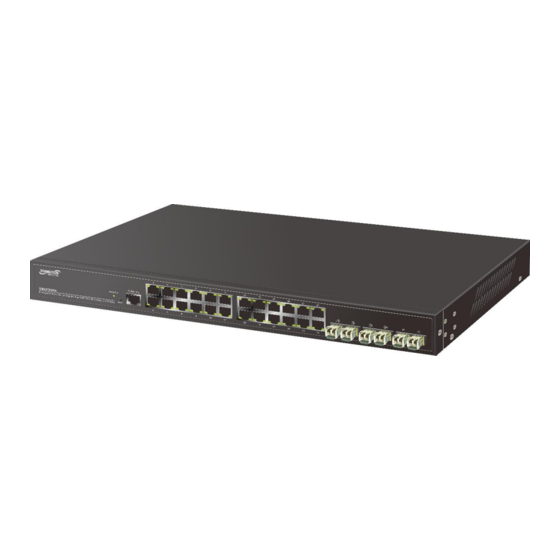
SM24T6DPA Web User Guide Application Examples The SM24T6DPA switch has 24 Gigabit copper ports and two 100/1000 dual speed SFPs. It is designed to segment your network, and to provide a wide range of options in setting up network connections. Some typical applications are: •... -
Page 9: Ethernet Cabling
Transition Networks SM24T6DPA Web User Guide Ethernet Cabling To ensure proper operation when installing the switch into a network, make sure that the current cables are suitable for 100BASE-TX or 1000BASE-T operation. Check the following criteria against the current installation of your network: •... - Page 10 Transition Networks SM24T6DPA Web User Guide WARNING: The mini-GBICs are Class 1 laser devices. Avoid direct eye exposure to the beam coming from the transmit port. CAUTION: Circuit devices are sensitive to static electricity, which can damage their delicate electronics. Dry weather conditions or walking across a carpeted floor may cause you to acquire a static electrical charge.
-
Page 11: Mounting
Transition Networks SM24T6DPA Web User Guide Mounting The switch can be mounted in a standard 19-inch equipment rack or on a desktop or shelf. Mounting instructions for each type of site as follows. Rack Mounting • Temperature: Since the temperature within a rack assembly may be higher than the ambient room temperature, check that the rack-environment temperature is within the specified operating temperature range (0 to 40 °C). -
Page 12: Desktop Or Shelf Mounting
Transition Networks SM24T6DPA Web User Guide Desktop or Shelf Mounting: Step 1. Attach the four adhesive rubber feet to the bottom of the first switch. Step 2. Set the device on a flat surface near an AC power source; make sure there are at least two inches of space on all sides for proper air flow. -
Page 13: Connecting To The Console Port
Transition Networks SM24T6DPA Web User Guide Connecting to the Console Port The RJ-45 serial port on the switch’s front panel is used to connect to the switch for out-of- band console configuration. The command line driven configuration program can be accessed from a terminal or a PC running a terminal emulation program. -
Page 14: Connecting To A Power Source
Transition Networks SM24T6DPA Web User Guide Connecting to a Power Source You can plug or remove the power cord from an AC power socket to turn power on and off. Inserting the Power Cord to AC Power Socket Step 1. Insert the power cable plug directly into the AC Socket located at the back of the switch. -
Page 15: Web-Based Management
Transition Networks SM24T6DPA Web User Guide Web-based Management The switch default values are listed below: IP Address 192.168.1.77 Subnet Mask 255.255.255.0 Default Gateway 192.168.1.254 Username admin Password admin After the managed switch has been configured in the CLI via the switch’s serial interface, you can browse it. -
Page 16: Connecting To Pcs, Servers, Hubs And Switches
Transition Networks SM24T6DPA Web User Guide Connecting to PCs, Servers, Hubs and Switches Step 1. Attach one end of a twisted-pair cable segment to the device’s RJ-45 connector. Step 2. If the device is a network card and the switch is in the wiring closet, attach the other end of the cable segment to a modular wall outlet connected to the wiring closet. -
Page 17: Fiber Optic Sfp
Transition Networks SM24T6DPA Web User Guide Fiber Optic SFP An optional Gigabit SFP transceiver can be used for a backbone connection between switches, or for connecting to a high-speed server. Each single-mode fiber port requires 9/125 micron single-mode fiber optic cable with an LC connector at both ends. -
Page 18: Cable Labeling And Connection Records
Transition Networks SM24T6DPA Web User Guide 1000BASE-T Cable Requirements When adding hubs to your network, please note that because switches break up the path for connected devices into separate collision domains, you should not include the switch or connected cabling in your calculations for cascade length involving other devices. -
Page 19: Troubleshooting
The result will be high error rates and very inefficient communications between the switch and the device. Make sure all devices connected to the SM24T6DPA are configured to auto negotiate or are configured to connect at half duplex (all hubs are configured this way, for example). -
Page 20: Troubleshooting Chart
Transition Networks SM24T6DPA Web User Guide Troubleshooting Chart Symptom Action 1. Check connections between the switch, the power cord and the POWER LED is Off wall outlet. 2. Contact your dealer for assistance. 1. Verify that the switch and attached device are powered on. -
Page 21: Cables
Transition Networks SM24T6DPA Web User Guide Cables Twisted-Pair Cable and Pin Assignments For 10/100BASE-TX connections, the twisted-pair cable must have two pairs of wires. For 1000BASE-T connections the twisted-pair cable must have four pairs of wires. Each wire pair is identified by two different colors. -
Page 22: 10/100Base-Tx Mdi And Mdi-X Port Pinouts
Transition Networks SM24T6DPA Web User Guide 10/100BASE-TX MDI and MDI-X Port Pinouts All 1000BASE-T ports support automatic MDI/MDI-X operation, so you can use straight- through cables for all network connections to PCs or servers, or to other switches or hubs. -
Page 23: Specifications
Transition Networks SM24T6DPA Web User Guide Specifications Physical Characteristics Connectors (1) RJ console port (20) 10/100/1000 RJ-45 ports (4) 100/1000 SFP/RJ-45 combo ports (2) 100/1000 SFP slots Network Interface Ports 1-20: RJ-45 connector, auto MDI/X 10BASE-T: RJ-45 (100-ohm, UTP cable; Category 3 or better) 100BASE-TX: RJ-45 (100-ohm, UTP cable;... -
Page 24: Switch Features
Transition Networks SM24T6DPA Web User Guide Switch Features Forwarding Mode Store-and-forward Throughput 35.712Mpps Flow Control Full Duplex: IEEE 802.3x Management Features In-Band Management SSH v1,v2/SSL, Telnet, SNMP, or HTTP Out-of-Band Management RS-232 (RJ-45) console port Software Loading HTTP, TFTP in-band, Console out-of-band Standards EEE 802.3 10Base-T Ethernet (Twisted-pair Copper) -
Page 25: Fcc-Class A
Transition Networks SM24T6DPA Web User Guide FCC-CLASS A This equipment has been tested and found to comply with the limits for a Class A computing device pursuant to Subpart J of part 15 of FCC Rules, which are designed to provide reasonable protection against such interference when operated in a commercial environment. - Page 26 10900 Red Circle Drive Minnetonka, MN 55343 USA Tel: 952- 941-7600 or 1-800-526-9267 Fax: 952-941-2322 Copyright© 2015-2019 Transition Networks. All rights reserved. Printed in the U.S.A. SM24T6DPA Install Guide, 33664 Rev B 33664 Rev. B https://www.transition.com/ Page 26 of 26...
Need help?
Do you have a question about the SM24T6DPA and is the answer not in the manual?
Questions and answers