Table of Contents
Advertisement
Quick Links
Advertisement
Table of Contents

Subscribe to Our Youtube Channel
Related Manuals for Transition Networks SM24DPB


Summary of Contents for Transition Networks SM24DPB
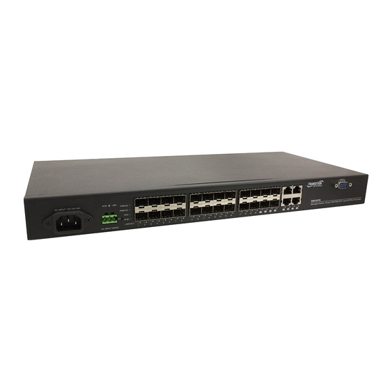
- Page 1 Transition Networks SM24DPB Install Guide SM24DPB Managed Layer 2 Gigabit Ethernet Switch (20) 100/1000Base‐X SFP Slots + (4) 100/1000Base‐X SFP/RJ‐45 Combo Ports Install Guide 33681 Rev. B 33681 Rev. B https://www.transition.com Page 1 of 24...
- Page 2 Anyone using this product in such an application without express written consent of an officer of Transition Networks does so at their own risk, and agrees to fully indemnify Transition Networks for any damages that may result from such use or sale.
-
Page 3: Table Of Contents
Transition Networks SM24DPB Install Guide Contents Safety Warnings and Cautions ........................... 2 Compliance and Safety Statements ........................ 3 Overview .................................. 5 About This Guide .............................. 5 Key Features ................................ 5 Benefits .................................. 5 Specifications ................................. 6 Front Panel................................ 10 Port and System Status LEDs .......................... 10 Installation ................................ 11 Unpacking ................................ 11 Selecting a Site .............................. 11 Troubleshooting ............................... 18 Related Manuals .............................. 18 Optional DC Power Supply ............................ 19 Industrial Power Supply 25104 (Mean Well SDR‐240‐48) ................... 19 25131 – Industrial DIN‐rail Mount Power Supply (MEANWELL SDR‐75‐48) ............ 20 DC Power Supply Wiring ............................ 21 Declaration of Conformity ............................ 21 Contact Us ................................ 22 Warranty .................................. 22 Compliance and Safety Statements This equipment has been tested and found to comply with the limits for a Class A computing device ... - Page 4 Transition Networks SM24DPB Install Guide CAUTION: Circuit devices are sensitive to static electricity, which can damage their delicate electronics. Dry weather conditions or walking across a carpeted floor may cause you to acquire a static electrical charge. To protect your device, always: • Touch the metal chassis of your computer to ground the static electrical charge before you pick up the circuit device. • Pick up the device by holding it on the left and right edges only. • If you need using outdoor device connect to this device with cable then you need to addition an arrester on the cable between outdoor device and this device. Addition of an arrester between outdoor device and this switch NOTE: The switch is indoor device; if it will be used in outdoor environment or connects with some outdoor device, then it must use a lightning arrester to protect the switch. WARNING: Self‐demolition on Product is strictly prohibited. Damage caused by self‐demolition will be charged for repairing fees. Before installation, make sure input power supply and product specifications are compatible to each other. To reduce the risk of electric shock. Disconnect all AC or DC power cord and RPS cables to completely remove power from the unit. Before importing / exporting configuration please make sure the firmware version is always the same. After firmware upgrade, the switch will move the configuration automatically to the latest firmware version. 33681 Rev. B https://www.transition.com...
-
Page 5: Overview
Transition Networks SM24DPB Install Guide Overview The SM24DPB L2+ Managed Switch is a next‐generation Fiber Switch offering full suite of L2 features including advanced L3 features such as Static Route that delivers the better cost performance and lower total cost of ownership in Enterprise networks or backbone via fiber or copper connections. The SM24DPB delivers 20 GbE SFP ports, 4 Combo GbE RJ45/SFP ports and DB9 Console port with built‐in AC and DC dual power supplies. SM24DPB provides front access to all data and management ports, and a compact form factor that facilitates desktop, wall‐mount, or rack‐mount installations. The SM24DPB is ideal to deliver management simplicity, better user experience, and lowest total cost of ownership. About This Guide This guide gives specific information on how to operate and use the management functions of the switch. The guide is intended for use by network administrators who are responsible for operating and maintaining network equipment; consequently, it assumes a basic working knowledge of general switch functions, the Internet Protocol (IP), and Simple Network Management Protocol (SNMP). Key Features L2+ Managed features provide easier manageability, robust security and QoS. AC/DC Dual Power Supply DHCP Server APR (Auto Power Reset) IPv4/IPv6 L3 static route IEEE 802.3az EEE Energy Efficient Ethernet standard for green Ethernet DMS (Device Management System) Benefits With the APR feature enabled, the switch automatically pings the device, and if the device fails, the switch toggles the PoE power, automatically resetting the device. Auto Power Reset eliminates the need for a manual reset of the device, saving time and money. These features make installation and ... -
Page 6: Specifications
Transition Networks SM24DPB Install Guide Specifications Port Configuration Total Ports SFPs (100M/1G) Uplinks (100M/1G) Console 24 20 4 RJ45/SFP Combo DB9 Hardware Performance Forwarding Capacity Switching Capacity Mac Table Jumbo Frames 35.712 Mpps 48 Gbps 32 K 10056 Bytes Environmental Range Operating Temperature Storage Temperature Altitude 32 to 140 deg. Fahrenheit ‐40 to 185 deg. Fahrenheit < 10000 Feet 0 to 60 deg. Centigrade ‐40 to 85 deg. Centigrade < 3000 Meters Dimension, Weights, Humidity Dimensions (WxHxD) Weight Operating Humidity 442 x 44 x 211 Millimeters 3.1 Kilograms 10% to 90% non‐condensing ... - Page 7 Transition Networks SM24DPB Install Guide Q‐in‐Q (double tag) VLAN Voice VLAN GARP VLAN Registration Protocol (GVRP) Relay of DHCP traffic to DHCP server in different VLAN. DHCP Relay Works with DHCP Option 82 IGMP limits bandwidth‐intensive multicast traffic to only the requesters. Supports IGMP v1/v2/v3 Snooping 1024 multicast groups IGMP querier is used to support a Layer 2 multicast domain of snooping switches in IGMP Querier the absence of a multicast router IGMP snooping with proxy reporting or report suppression actively filters IGMP IGMP Proxy packets in order to reduce load on the multicast router MLD v1/v2 Snooping Delivers IPv6 multicast packets only to the required receivers Layer 2 Switching IPv4 Static Routing IPv4 Unicast: Static routing IPv6 Static Routing IPv6 Unicast: Static routing Security Secure Shell (SSH) SSH secures Telnet traffic in or out of the switch, SSH v1 and v2 are supported SSL encrypts the http traffic, allowing advanced secure access to the browser‐based Secure Sockets Layer (SSL) management GUI in the switch IEEE802.1X: RADIUS authentication, authorization and accounting, MD5 hash, ...
- Page 8 Transition Networks SM24DPB Install Guide Ingress policer Egress shaping and rate control Rate Limiting Per port Management DHCP Server Support DHCP server to assign IP to DHCP clients Embedded RMON agent supports RMON groups 1,2,3,9 (history, statistics, alarms, Remote Monitoring (RMON) and events) for enhanced traffic management, monitoring and analysis Traffic on a port can be mirrored to another port for analysis with a network Port Mirroring analyzer or RMON probe. Up to N‐1 (N is Switch’s Ports) ports can be mirrored to single destination port. A single session is supported. The Universal Plug and Play Forum, an industry group of companies working to UPnP enable device‐to‐device interoperability by promoting Universal Plug and Play. The industry standard for monitoring high speed switched networks. It gives sFlow complete visibility into the use of networks enabling performance optimization, accounting/billing for usage, and defense against security threats Used by network devices for advertising their identities, capabilities, and IEEE 802.1ab (LLDP) neighbors on an IEEE 802ab local area network Support LLDP‐MED extensions Web GUI Interface ...
- Page 9 Transition Networks SM24DPB Install Guide Hardware Description 1000BASE‐T Ports: The switch contains 10/100/1000BASE‐T RJ‐45 ports. All RJ‐45 ports support automatic MDI/MDI‐X operation, auto‐negotiation and IEEE 802.3x auto‐negotiation of flow control, so the optimum data rate and transmission can be selected automatically. SFP Transceiver Slots: The switch supports the Small Form Factor Pluggable (SFP) transceiver slots port 1 to port 24, ports 21 to 24 are shared with RJ‐45 (ports 21‐24 are combo interface RJ45/SFP). In the default configuration, if an SFP transceiver (purchased separately) is installed in a slot and has a valid link on the port, the associated RJ‐45 port is disabled. 33681 Rev. B https://www.transition.com Page 9 of 24...
-
Page 10: Front Panel
Transition Networks SM24DPB Install Guide Front Panel Port and System Status LEDs LED: P1‐P24 SFP Link/Act/Speed Condition: Green/ Amber Status: Lights when Fiber connection with remote device is good. Blinks when any traffic is present. The light is green when linking up at 1000Mbps.The light is Amber when linking up at 100Mbps. LED: P21‐P24 TP Link/Act/Speed Condition: Green/ Amber Status: Blinks when any traffic is present. The light is green when linking up 10/1000Mbps. The light is Amber when linking up 100Mbps. System LED: PWR AC Condition: Green Status: Lights when power on from AC source. System LED: PWR DC Condition: Green Status: Lights when power on from DC source. System LED: SYS Condition: Green Status: Blinking when system is booting; lit when system is coming up. System LED: ALM (Alarm) Condition: Red Status: Always off; until any message about system error lights the ALM LED. RST (Reset) button: push to reset the SM24DPB; requires a re‐login. 33681 Rev. B https://www.transition.com... -
Page 11: Installation
Transition Networks SM24DPB Install Guide Power Supply Sockets: There are dual power inputs on the front panel of the switch for power redundancy requirement, the SM24DPB switch has 100~240 VAC power socket for AC power Input and ‐36VDC ~ ‐48VDC power input via terminal block. Installation Unpacking Verify that you have received the packing items. □ One SM24DPB GbE Fiber Managed Switch □ Four adhesive rubber feet □ Mounting Accessory (for 19”Rack Shelf) □ One printed Quick Start Guide □ AC Power Cord □ RS232 DB9 to DB9 Cable An optional DC Power Supply may be included. Contact your sales representative if any items are missing or damaged. Save the packaging for possible future use. Selecting a Site The Switch can be mounted in a standard 19‐inch equipment rack (via Rack mount Kit). Be sure to follow the guidelines below when choosing a location. ◆ The site should: Be at the center of all the devices you want to link and near a power outlet. Be able to maintain its temperature within ‐20 to 60°C and its humidity within 5% to 95%, non‐ condensing. Be accessible for installing, cabling and maintaining the devices. ... - Page 12 Transition Networks SM24DPB Install Guide Ethernet Cabling To ensure proper operation when installing the switch into a network, make sure that the current cables are suitable for 100BASE‐TX or 1000BASE‐T operation. Check the following criteria against the current installation of your network: ◆ Cable type: Unshielded twisted pair (UTP) or shielded twisted pair (STP) cable with RJ‐45 connectors; Category 5 or Category 5e with maximum length of 100 meters is recommend 100BASE‐TX, and Category 5e or 6 with maximum length of 100 meters is recommend for 1000BASE‐T. ◆ Protection from radio frequency interference emissions. ◆ Electrical surge suppression. ◆ Separation of electrical wires and data based network wiring. ◆ Safe connections with no damaged cables, connectors or shields. ◆ RJ-45 Connections SFP Transceiver ◆ WARNING: SFPs and mini‐GBICs are Class 1 laser devices. Avoid direct eye exposure to the beam coming from the transmit port. 33681 Rev. B https://www.transition.com Page 12 of 24...
- Page 13 Transition Networks SM24DPB Install Guide Mounting The switch can be mounted in a standard 19‐inch equipment rack or on a desktop or shelf. Mounting instructions for each type is provided below. Rack Mounting (Optional): Before rack mounting the switch, please pay attention to the following factors: Temperature: Since the temperature within a rack assembly may be higher than the ambient room temperature, check that the rack‐environment temperature is within the specified operating temperature range (‐20 to 60 °C). Mechanical Loading: Do not place any equipment on top of a rack‐mounted unit. Circuit Overloading: Be sure that the supply circuit to the rack assembly is not overloaded. Grounding: Rack‐mounted equipment should be properly grounded. Step 1. Attach the brackets to the device using the screws provided in the Mounting Accessory. Step 2. Mount the device in the rack (via Rack‐Mount kit), using four rack‐mounting screws (not provided). Be sure to secure the lower rack‐mounting screws first to prevent the brackets being bent by the weight of the switch. Step 3. If installing a single switch only, turn to “Connecting to Power” on page 15. Step 4. If installing multiple switches, mount them in the rack, one below the other, in any order. 33681 Rev. B https://www.transition.com Page 13 of 24...
- Page 14 Transition Networks SM24DPB Install Guide Desktop or Shelf Mounting Step 1. Attach the four adhesive rubber feet to the bottom of the first switch. Step 2. Set the device on a flat surface near an AC power source, making sure there are at least two inches of space on all sides for proper air flow. Step 3. If installing a single switch only, go to “Connecting to Power” on page 15. Step 4. If installing multiple switches, attach four adhesive feet to each one. Place each device squarely on top of the one below, in any order. 33681 Rev. B https://www.transition.com Page 14 of 24...
- Page 15 Transition Networks SM24DPB Install Guide Installing an Optional SFP Transceiver You can install or remove a mini‐GBIC SFP from a mini‐GBIC slot without having to power off the switch. Use only Manufacture mini‐GBIC. NOTE: The mini‐GBIC slots are shared with the four 10/ 100/ 1000Base‐T RJ‐45 ports. If a mini‐GBIC is installed in a slot, the associated RJ‐45 port is disabled and cannot be used. SFP transceivers are not provided in the switch package. The mini‐GBIC ports operate only at full duplex. Half duplex operation is not supported. Ensure the network cable is NOT connected when you install or remove a mini‐GBIC. Inserting an SFP Transceiver into a Slot Step 1. Consider network and cabling requirements to select an appropriate SFP transceiver type. Step 2. Insert the transceiver with the optical connector facing outward and the slot connector facing down. Note that SFP transceivers are keyed so they can only be installed in one orientation. Step3 . Slide the SFP transceiver into the slot until it clicks into place. Connecting to Power Make cable connections before connecting Power. Connecting to AC Power Source You can plug or remove an AC power cord through the AC socket from AC power source. ...
- Page 16 Transition Networks SM24DPB Install Guide Serial Cable Wiring (cross cable for console port not supported) Switch’s 8‐Pin Serial Port PC’s 9‐Pin DTE Port Fiber Optic SFP Devices An optional Gigabit SFP transceiver can be used for a backbone connection between switches, or for connecting to a high‐speed server. Each single‐mode fiber port requires 9/125 micron single‐mode fiber optic cable with an LC connector at both ends. Each multimode fiber optic port requires 50/125 or 62.5/125 micron multimode fiber optic cabling with an LC connector at both ends. WARNING: This switch uses lasers to transmit signals over fiber optic cable. The lasers are inherently eye safe in normal operation. However, user should never look directly at a transmit port when it is powered on. WARNING: When selecting a fiber SFP device, considering safety, please make sure that it can function at a temperature that is not less than the recommended maximum operational temperature of the product. You must also use an approved Laser SFP transceiver. Step 1. Remove and keep the LC port’s rubber plug. When not connected to a fiber cable, the rubber plug should be replaced to protect the optics. Step 2. Check that the fiber terminators are clean. You can clean the cable plugs by wiping them gently with a clean tissue or cotton ball moistened with a little ethanol. Dirty fiber terminators on fiber optic cables will impair the quality of the light transmitted through the cable and lead to degraded performance on the port. 33681 Rev. B https://www.transition.com Page 16 of 24...
- Page 17 Transition Networks SM24DPB Install Guide Step 3. Connect one end of the cable to the LC port on the switch and the other end to the LC port on the other device. Since LC connectors are keyed, the cable can be attached in only one orientation. Step 4. As a connection is made, check the Link LED on the switch corresponding to the port to be sure that the connection is valid. The fiber optic ports operate at 1 Gbps. The maximum length for fiber optic cable operating at Gigabit speed will depend on the fiber type as listed under “1000 Mbps Gigabit Ethernet Collision Domain”. Connectivity Rules When adding hubs to your network, please note that because switches break up the path for connected devices into separate collision domains, you should not include the switch or connected cabling in your calculations for cascade length involving other devices. 33681 Rev. B https://www.transition.com Page 17 of 24...
-
Page 18: Troubleshooting
Transition Networks SM24DPB Install Guide Troubleshooting Most problems are caused by the following situations. Check for these items first when starting your troubleshooting: 1. Connecting to devices that have a fixed full‐ duplex configuration. Make sure all devices connected to the SM16TAT2DPA Switch devices are configured to auto negotiate, or are configured to connect at half duplex. 2. Faulty or loose cables. Look for loose or obviously faulty connections. If they appear to be OK, make sure the connections are snug. If that does not correct the problem, try a different cable. 3. Non‐standard cables. Non‐standard and miswired cables may cause network collisions and other network problems, and can seriously impair network performance. Use a new correctly‐wired cable. A Category 5 cable tester is a recommended tool for every 100Base‐TX and 1000Base‐T network installation. 4. Improper Network Topologies. It is important to make sure you have a valid network topology. If you no longer experience the problems, the new topology is probably at fault. In addition, you should make sure that your network topology contains no data path loops. 5. Check the port configuration. A port on your Switch may not be operating as you expect because it has been put into a “blocking” state by Spanning Tree, GVRP (automatic VLANs), or LACP (automatic trunking). (Note that the normal operation of the Spanning Tree, GVRP, and LACP features may put the port in a blocking state.) Or, the port just may have been configured as disabled through software. 6. SYS LED is Off. Check connections between the switch, the power cord and the wall outlet. Contact Tech Support for assistance. See Contact Us below. 7. Link LED is Off. Verify that the switch and attached device are powered on. Be sure the cable is plugged into the switch and corresponding device. If the switch is installed in a rack, check the connections to the punch‐ down block and patch panel. Verify that the proper cable type is used and its length does not exceed specified limits. Check the adapter on the attached device and cable connections for possible defects. Replace the defective adapter or cable if necessary. 8. Contact Transition Networks Tech Support for assistance. See Contact Us below. Related Manuals ... -
Page 19: Optional Dc Power Supply
Transition Networks SM24DPB Install Guide Optional DC Power Supply The SM24DPB provides dual power inputs on the front panel of the switch for power redundancy requirement. The SM24DPB switch has 100~240 VAC power socket for AC power Input and ‐36VDC ~ ‐48VDC power input via terminal block. With the AC/DC Dual Power Supply, power failover occurs when power supplies are connected to different circuits for reduced network operating risk. Several power supply models are available from Transition Networks. Warning: You must use an isolated power supply in order for Transition Networks to honor the warranty. The power supplies that Transition Networks makes available are: □ 25105 ‐ Mean Well SDR‐120‐48 □ 25131 – MEANWELL SDR‐75‐48 Industrial Power Supply 25104 (Mean Well SDR‐240‐48) INPUT: 100‐240VAC 2.6A 50/60 Hz OUTPUT: 48V ‐ 5A “Use copper wire only” “Maximum surrounding air temperature: 60°C” “Instructions for installation in a pollution degree 2 environment” Terminal Torque: 7 Lb‐in (DC connections at top of PS). Terminal Torque: 4.4 Lb‐in (AC connections at bottom of PS). +V ADJ: access to small Phillips screw; turn clockwise to increase voltage. Adjustable, 48‐55V. DC OK LED: lights to indicate a DC OK condition. With both the AC and DC (25105) Power Supplies connected both the CLI and the web GUI show: AC Power On 11.95V ; DC Power On 11.86V. With just the DC supply connected the ALM (Alarm) LED lights in Red. See the SM24DPB Quick Start Guide for Power Requirements, Isolation, Redundant Power Inputs, Power Connection, and/or Chassis Ground information. 33681 Rev. B https://www.transition.com... -
Page 20: 25131 - Industrial Din-Rail Mount Power Supply (Meanwell Sdr-75-48)
Transition Networks SM24DPB Install Guide 25131 – Industrial DIN‐rail Mount Power Supply (MEANWELL SDR‐75‐48) See the online product page for more information. Features Auto‐Negotiation Variable AC input range Protected against Overload, Over Voltage, and Over Temperature Convection air cooling DIN Rail mountable UL 508 approved RoHS compliant MTBF 481.9Khrs Specifications Output Output Voltage: 48VDC Current Rating: 1.6A Power Rating: 76.8 Watts Ripple & Noise Max: 120mVp‐p Voltage Range: 48~55VDC Voltage Tolerance: ±1.0% Line Regulation: ±0.5% Load Regulation: ±1.0% Input Voltage Range Switch Selectable: 88~264VAC, 124~370VDC Frequency Range: 47~63Hz Efficiency: 90% Protection Overload: 110~150% Overvoltage: 56~65.8V Dimensions: Width: 1.26” [32 mm] x Depth: 4.02” [102 mm] x Height: 4.93” [125.2 mm] Environment Operating: ‐30°C to +70°C Storage: ‐40°C to +85°C Humidity: 20% to 95% (non‐condensing) ... -
Page 21: Dc Power Supply Wiring
Transition Networks SM24DPB Install Guide DC Power Supply Wiring Declaration of Conformity 33681 Rev. B https://www.transition.com Page 21 of 24... -
Page 22: Contact Us
Transition Networks SM24DPB Install Guide Contact Us Technical Support Technical support is available 24‐hours a day US and Canada: 1‐800‐260‐1312 International: 00‐1‐952‐941‐7600 Main Office tel: +1.952.941.7600 | toll free: 1.800.526.9267 | fax: 952.941.2322 sales@transition.com | techsupport@transition.com | customerservice@transition.com Address Transition Networks 10900 Red Circle Drive Minnetonka, MN 55343, U.S.A. Web: https://www.transition.com Warranty Limited Lifetime Warranty Effective for Products Shipped May 1, 1999 and After. Every Transition Networks labeled product purchased after May 1, 1999, and not covered by a fixed‐duration warranty will be free from defects in material and workmanship for its lifetime. This warranty covers the original user only and is not transferable. This warranty does not cover damage from accident, acts of God, neglect, contamination, misuse or abnormal conditions of operation or handling, including over‐voltage failures caused by use outside of the product’s specified rating, or normal wear and tear of mechanical components. Transition Networks will, at its option: •Repair the defective product to functional specification at no charge •Replace the product with an equivalent functional product •Refund a portion of purchase price based on a depreciated value To return a defective product for warranty coverage, contact Transition Networks’ Customer Support for a return authorization number. Send the defective product postage and insurance prepaid to the following address: Transition Networks, Inc. 10900 Red Circle Drive Minnetonka, MN 55343 USA ... - Page 23 Transition Networks SM24DPB Install Guide invoice will be generated for payment on any unit(s) not returned within 30 days after the demo/ evaluation period has expired. The customer must pay for the non‐compliant product(s) return transportation costs to Transition Networks for evaluation of said product(s) for repair or replacement. Transition Networks will pay for the shipping of the repaired or replaced in‐warranty product(s) back to the customer (any and all customs charges, tariffs, or/and taxes are the customer’s responsibility). Before making any non‐warranty repair, Transition Networks requires a $200.00 charge plus actual shipping costs to and from the customer. If the repair is greater than $200.00, an estimate is issued to the customer for authorization of repair. If no authorization is obtained, or the product is deemed not repairable, Transition Networks will retain the $200.00 service charge and return the product to the customer not repaired. Non‐ warranted products that are repaired by Transition Networks for a fee will carry a 180‐day limited warranty. All warranty claims are subject to the restrictions and conventions set forth by this document. Transition Networks reserves the right to charge a $50 fee for all testing and shipping incurred, if after testing, a return is classified as “No Problem Found.” THIS WARRANTY IS YOUR ONLY REMEDY. NO OTHER WARRANTIES, SUCH AS FITNESS FOR A PARTICULAR PURPOSE, ARE EXPRESSED OR IMPLIED. TRANSITION NETWORKS IS NOT LIABLE FOR ANY SPECIAL, INDIRECT, INCIDENTAL OR CONSEQUENTIAL DAMAGES OR LOSSES, INCLUDING LOSS OF DATA, ARISING FROM ANY CAUSE OR THEORY. AUTHORIZED RESELLERS ARE NOT AUTHORIZED TO EXTEND ANY DIFFERENT WARRANTY ON TRANSITION NETWORKS’S BEHALF. 33681 Rev. B https://www.transition.com Page 23 of 24...
- Page 24 Transition Networks SM24DPB Install Guide Transition Networks 10900 Red Circle Drive Minnetonka, MN 55343 USA Tel: 952‐ 941‐7600 or 1‐800‐526‐9267 Fax: 952‐941‐2322 Copyright© 2016‐2018 Transition Networks. All rights reserved. SM24DPB Managed Fiber Switch Install Guide 33681 Rev. B 33681 Rev. B https://www.transition.com Page 24 of 24...
Need help?
Do you have a question about the SM24DPB and is the answer not in the manual?
Questions and answers