Advertisement
Transition Networks
SMxxTAT4Xx Quick Start Guide
SMxxTAT4Xx Family
SM48TAT4XA‐RP and SM24TAT4XB
Quick Start Guide
The Transition Networks SM48TAT4XA‐RP is a 48‐port Gigabit Managed PoE+ Switch with Redundant Power
Supplies (820 Watts PoE budget with single Power supply, 1620Watts PoE budget with dual Power Supplies).
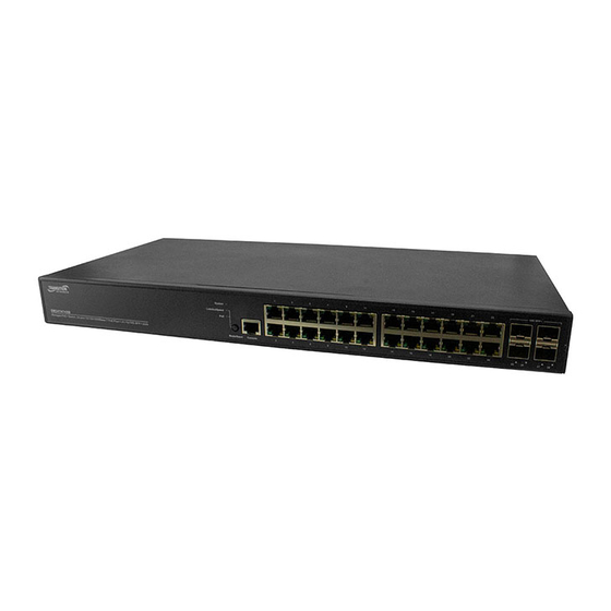
The SM24TAT4XB is a 24‐port Gigabit Managed PoE+ Switch with (4) 1G/10G SFP+ ports and 370 Watt PoE
budget.
Note: See the Install Guide for important Safety Warnings and Cautions, Ordering Information, Specifications, AC
Power Connector, Installation, Mounting, Troubleshooting, Compliance, Regulatory, and Warranty information.
Front Panels: The front panel contains the Ports, LEDs, Console Port, and Mode/Reset button as described below.
Console Port: Provides an RJ‐45 Console port to connect to a PC or terminal for CLI command entry.
10/100/1000 RJ45 Ports: The SM48TAT4XA‐RP provides 48 10M/100M/1G (RJ45) ports. The SM24TAT4XB
provides 24 10M/100M/1G (RJ45) ports.
1G/10G SFP+ Ports: The SM48TAT4XA‐RP and the SM24TAT4XB both provide four SFP+ uplink ports.
System LED: Indicates if the switch is powered up correctly or indicates if there is a system alarm triggered.
The System LED is Off when switch is not receiving power. On Green when switch is powered ON correctly.
The System LED is On Red in abnormal state, such as exceeding operating temperature range, was detected.
Power LEDS (SM48TAT4XA‐RP only): Indicates if the switch power supply A/B powered up correctly or not.
Port Status LEDs: Indicates the current status of each port. These LEDs display port status in different modes;
after changing the mode by pressing the Mode/Reset button.
Mode LED: Indicates the mode of all ports on the switch. You can press the Mode/Reset button sequentially to
switch between the two modes (Link/Activity/Speed mode and PoE mode).
Port Status LEDs: TP port LED is Green/Amber. For Ethernet Mode: • 1G Link/Act: Green Color # RJ45 Port Left
LED Behavior: => Light off: port disconnected or link failed. => Green Light on: Link Present, No Activity
=> Green Blinking: Activity. Port is sending or receiving data. • 10M/100M Link/Act: Amber Color. # RJ45 Port
Right LED Behavior: =>Light off: port disconnected or link failed. =>Amber Light on: Link Present, No Activity.
=>Amber Blinking: Activity. Port is sending or receiving data.
SFP+ Port LED is Green/Blue. LNK: Blue/Green (Two Color). Light off: port disconnected or link failed. Green Light
on: link‐up (1G). Blue Light on: link‐up (10G). ACT: Blinking: activity (receiving or transmitting data).
Mode LEDs: POWER/Alarm LED is Green/Red. • SYS: Green/Red Bi‐Color; Light off: Power Off; Green Lit: the
switch in power on system initialization process. => Red Lit: Indicates a malfunction. Contact technical support.
=> Green Blinking: Indicates that the switch is running normally. => Red Blinking: N/A.
Link/Act/ Speed LED is Green. The Port Status LEDs are displaying link status, network activity and speed of each
port. • SYS: Green Single Color. • Use Mode / Reset Button to change Mode. => Light off: Changed Port LED to
Other Mode. => Green Light on: Change Port LED to Link/Act/Speed Mode. By pressing the Mode/Reset button
for less than 2 seconds to change LED modes (Link/Act/Speed Mode or PoE Mode) you can check the port status
by reading the LED behaviors. See the Install Guide.
Mode/Reset button: By pressing the Mode/Reset Button for certain period of time, you can: Change Port Status
LED Mode: To read the port status correctly in the two different modes (Link/Act/Speed mode or PoE mode).
Reset the Switch: To reboot and get the switch back to the previous configuration settings saved.
Restore the Switch to Factory Defaults: To restore the original factory default settings back to the switch.
Note: You can determine which task is being performed by reading the LED behaviors while pressing the
Mode/Reset button. Once the LED behaviors are correctly displayed, just release the button.
33784 Rev. A
https://www.transition.com
Page 1 of 2
Advertisement
Table of Contents

Related Manuals for Transition Networks SM TAT4X Series


Summary of Contents for Transition Networks SM TAT4X Series
- Page 1 Transition Networks SMxxTAT4Xx Quick Start Guide SMxxTAT4Xx Family SM48TAT4XA‐RP and SM24TAT4XB Quick Start Guide The Transition Networks SM48TAT4XA‐RP is a 48‐port Gigabit Managed PoE+ Switch with Redundant Power Supplies (820 Watts PoE budget with single Power supply, 1620Watts PoE budget with dual Power Supplies). The SM24TAT4XB is a 24‐port Gigabit Managed PoE+ Switch with (4) 1G/10G SFP+ ports and 370 Watt PoE budget. Note: See the Install Guide for important Safety Warnings and Cautions, Ordering Information, Specifications, AC Power Connector, Installation, Mounting, Troubleshooting, Compliance, Regulatory, and Warranty information. Front Panels: The front panel contains the Ports, LEDs, Console Port, and Mode/Reset button as described below. Console Port: Provides an RJ‐45 Console port to connect to a PC or terminal for CLI command entry. 10/100/1000 RJ45 Ports: The SM48TAT4XA‐RP provides 48 10M/100M/1G (RJ45) ports. The SM24TAT4XB provides 24 10M/100M/1G (RJ45) ports. 1G/10G SFP+ Ports: The SM48TAT4XA‐RP and the SM24TAT4XB both provide four SFP+ uplink ports. System LED: Indicates if the switch is powered up correctly or indicates if there is a system alarm triggered. The System LED is Off when switch is not receiving power. On Green when switch is powered ON correctly. The System LED is On Red in abnormal state, such as exceeding operating temperature range, was detected. Power LEDS (SM48TAT4XA‐RP only): Indicates if the switch power supply A/B powered up correctly or not. Port Status LEDs: Indicates the current status of each port. These LEDs display port status in different modes; after changing the mode by pressing the Mode/Reset button. Mode LED: Indicates the mode of all ports on the switch. You can press the Mode/Reset button sequentially to switch between the two modes (Link/Activity/Speed mode and PoE mode). Port Status LEDs: TP port LED is Green/Amber. For Ethernet Mode: • 1G Link/Act: Green Color # RJ45 Port Left LED Behavior: => Light off: port disconnected or link failed. => Green Light on: Link Present, No Activity => Green Blinking: Activity. Port is sending or receiving data. • 10M/100M Link/Act: Amber Color. # RJ45 Port Right LED Behavior: =>Light off: port disconnected or link failed. =>Amber Light on: Link Present, No Activity. =>Amber Blinking: Activity. Port is sending or receiving data. SFP+ Port LED is Green/Blue. LNK: Blue/Green (Two Color). Light off: port disconnected or link failed. Green Light on: link‐up (1G). Blue Light on: link‐up (10G). ACT: Blinking: activity (receiving or transmitting data). ...
- Page 2 Transition Networks SMxxTAT4Xx Quick Start Guide Mode/Reset Button: Change LED Mode: Press the button for 0~2 seconds; the SYS LED is On green; the LED status changes based on the mode selected. Reset Switch: Press the button for 2~7 seconds; the SYS LED blinks green; all port status LEDs are Off. Restore to Defaults: Press the button for 7~12 seconds; the SYS LED blinks green; all port status LEDs stay On. Back Panels: The SM48TAT4XA‐RP back panel contains the AC Power Connector(s), DC and AC LEDs, and a 2 AC Power Connector. The SM24TAT4XB back panel contains the AC Power Connector. AC Power Connector: The back panel provides the AC Power Connector marked AC Line: 100‐200V 50‐60Hz. Installation Package Contents: Carefully unpack the switch from the packaging and verify you received one Switch, one AC Power cord, four rubber feet, this document, two 19" Ear Rack Brackets, 8 Screws, 2 screws for power plate cover, one DB9F to RJ45 Plug Console Cable, EPE for PSU (x2, ‐RP only), and one Post card. Mount Switch in a 19‐inch Rack: 1. Attach the mounting brackets to both sides of the chassis. Insert screws and tighten to secure the brackets. 2. Place the switch on a rack shelf in the rack. Push it in until the holes in the brackets align with the holes in the rack posts. 3. Attach the brackets to the posts. Insert screws and tighten. Mount Switch on Desk or Shelf: 1. Verify that the workbench is sturdy and reliably grounded. 2. Attach the four adhesive rubber feet to the bottom of the switch. Install SFP+ Modules:. 1. Position the SFP device at either installation slot, with the SFP label facing up on upper SFP slots or down on lower SFP slots. 2. Carefully slide the SFP device into the slot. 3. Press firmly so that the SFP device is firmly seated. 4. Attach an appropriate cable into the SFP module port. 5. Attach the other end of the cable to the other device. Connect Powered Devices (PDs): Note: this device does not comply with IEEE 802.3at at 48‐51.4 VDC, or with IEE 802.3bt at 48‐53.4 VDC. The latest device label indicates:802.3af: 48‐57VDC. 802.3at: 52‐57VDC. 802.3bt: 54‐57VDC. This device drops ~1.3V from Vin to PSEout. IEEE requires PSEout voltages at the PSE output into the cable: 802.3af: 44VDC. 802.3at: 50VDC. 802.3bt: 52VDC. Not meeting this PSEout requirement may cause power up failures or power cycling with devices drawing the maximum power with maximum cable loss. Power Connection: Warning: Connect the power supply to the switch first, and then connect the power supply to power. Otherwise catastrophic product failure may occur. Place an appropriate safety flag and lockout device at the source power circuit breaker, or place a piece of adhesive tape over the circuit breaker handle to prevent accidental power restoration while you are working on the circuit. Power Disconnection: To disconnect power from the switch after a successfully boot: 1. Turn off power to the switch. 2. Disconnect the cables. ...
Need help?
Do you have a question about the SM TAT4X Series and is the answer not in the manual?
Questions and answers