Transition Networks SM12DP2XA Install Manuals
Managed gigabit ethernet fiber switch.
(12) 100/1000base-x sfp slots + (2) 1g/10g sfp+ slots +
(2) 10/100/1000base-t
Hide thumbs
Also See for SM12DP2XA:
- Cli reference manual (254 pages) ,
- Quick start manual (2 pages) ,
- Install manual (32 pages)
Table of Contents
Advertisement
Quick Links
Download this manual
See also:
Cli Reference Manual
Advertisement
Table of Contents
Troubleshooting

Related Manuals for Transition Networks SM12DP2XA


Summary of Contents for Transition Networks SM12DP2XA
- Page 1 Transition Networks SM12DP2XA Install Guide SM12DP2XA Managed Gigabit Ethernet Fiber Switch (12) 100/1000Base-X SFP Slots + (2) 1G/10G SFP+ slots + (2) 10/100/1000Base-T Install Guide 33751 Rev. C 33751 Rev. C https://www.transition.com Page 1 of 32...
- Page 2 Transition Networks SM12DP2XA Install Guide Trademarks All trademarks and registered trademarks are the property of their respective owners. Copyright Notice/Restrictions Copyright© 2018 Transition Networks. All rights reserved. No part of this work may be reproduced or used in any form or by any means (graphic, electronic or mechanical) without written permission from Transition Networks. Printed in the U.S.A. SM12DP2XA Managed Gigabit Ethernet Fiber Switch Install Guide 33751 Rev. B Contact Information Transition Networks 10900 Red Circle Drive Minnetonka, MN 55343 USA tel: +1.952.941.7600 | toll free: 1.800.526.9267 | fax: 952.941.2322 sales@transition.com | techsupport@transition.com | customerservice@transition.com Revision History Rev Date Description A 6/25/18 Initial release at FW v7.10. 1423 2018‐05‐16. B 7/27/18 Update DC Input terminal and compliance information. C 8/22/18 Correct the default IP address. 33751 Rev. C https://www.transition.com Page 2 of 32...
- Page 3 Transition Networks SM12DP2XA Install Guide Cautions and Warnings Definitions Cautions indicate that there is the possibility of poor equipment performance or potential damage to the equipment. Warnings indicate that there is the possibility of injury to person. Cautions and Warnings appear here and may appear throughout this manual where appropriate. Failure to read and understand the information identified by this symbol could result in poor equipment performance, damage to the equipment, or injury to persons. Cautions While installing or servicing the power module, wear a grounding device and observe all electrostatic discharge precautions. Failure to observe this caution could result in damage to, or failure of the power module. Warnings Warning: Do not connect the power module to an external power source before installing it into the chassis. Failure to observe this warning could result in an electrical shock, even death. WARNING: Equipment grounding is vital to ensure safe operation. The installer must ensure that the power module is properly grounded during and after installation. Failure to observe this warning could result in an electric shock, even death. WARNING: A readily accessible, suitable National Electrical Code (NEC) or local electrical code approved disconnect device and branch‐circuit protector must be part of the building's installed wiring to accommodate permanently connected equipment. Failure to observe this warning could result in an electric shock, even death. WARNING: Turn any external power source OFF and ensure that the power module is disconnected from the external power source before performing any maintenance. Failure to observe this warning could result in an electrical shock, even death. WARNING: Ensure that the disconnect device for the external power source is OPEN (turned OFF) before disconnecting or connecting the power leads to the power module. Failure to observe this warning could result in an electric shock, even death. Electrical Safety Warnings on page for Electrical Safety Warnings translated into multiple languages.
-
Page 4: Table Of Contents
Transition Networks SM12DP2XA Install Guide Contents Introduction ................................. 6 Safety Statements ................................ 6 Features .................................. 7 Benefits .................................. 7 Specifications ................................ 8 Switch Architecture ..............................12 Network Management Options ..........................12 About This Manual ..............................12 Related Manuals ................................13 For More Information ..............................13 Front Panel .................................14 1000BASE‐T Ports ..............................14 SFP and SFP+ Transceiver Slots ..........................14 CONSOLE Port ................................14 Front Panel LEDs ..............................15 Port Status LEDs ..............................15 System Status LEDs ..............................15 RST (Reset) Button ..............................16 Power Supply Inputs ..............................16 Installation .................................17 Site Selection ................................17 ... - Page 5 Transition Networks SM12DP2XA Install Guide Limited Lifetime Warranty .............................28 Contact Us ................................28 Technical Support...............................28 Compliance Information ............................29 FCC Regulations ..............................29 Canadian Regulations .............................29 Declaration of Conformity (DoC) ...........................29 High Risk Activities Disclaimer ..........................30 Electrical Safety Warnings ............................31 Electrical Safety ..............................31 Elektrische Sicherheit ............................31 Elektrisk sikkerhed .............................31 Elektrische veiligheid ............................31 Sécurité électrique .............................31 Sähköturvallisuus ...............................31 Sicurezza elettrica ..............................31 Elektrisk sikkerhet ..............................31 Segurança eléctrica ............................31 Seguridad eléctrica .............................31 Elsäkerhet ................................31 ...
-
Page 6: Introduction
Transition Networks SM12DP2XA Install Guide Introduction The SM12DP2XA Managed Gigabit Ethernet Fiber Switch is a next‐generation Fiber Switch offering full suite of L2 features and additional 10GbE uplink connections. Advanced L3 features such as Static Route deliver better cost performance and lower total cost of ownership in Enterprise networks or backbone via fibber or copper connections. The SM12DP2XA provides 12 GbE SFP ports, 2 RJ45 ports, 2 10GbE SFP+ ports and RJ45 Console port with built‐in AC and DC dual power supplies. SM12DP2XA provides front panel access to all power, data, and management ports, in a compact form factor for desktop, wall‐mount, or rack‐mount installations. The SM12DP2XA delivers management simplicity, better user experience, and lowest total cost of ownership. The built‐in Device Managed System (DMS) is designed to be extremely easy to use, manage, and install IP Phones, IP Cameras, or Wifi‐APs for Enterprise applications. Safety Statements CAUTION: Circuit devices are sensitive to static electricity, which can damage their delicate electronics. Dry weather conditions or walking across a carpeted floor may cause you to acquire a static electrical charge. To protect your device: Touch the metal chassis of your computer to ground the static electrical charge before you pick up the circuit device. Pick up the device by holding it on the left and right edges only. If you need to use an outdoor device connected to this device with cable then you must use an arrester on the cable between outdoor device and this device. NOTE: The switch is an indoor device; if it will be used in an outdoor environment or to connect with an outdoor device, then it must use a lightning arrester to protect the switch WARNING: • Self‐demolition of this product is strictly prohibited. Damage caused by self‐demolition will be charged for repairing fees. See the US EPA Electronics Donation and Recycling website. •... -
Page 7: Features
Transition Networks SM12DP2XA Install Guide Features IPv6 Management Support Jumbo Frame up to 10200 bytes Authentication – RADIUS, TACACS+ IEEE 802.1X: RADIUS authentication, authorization and accounting, MD5 hash, guest VLAN, single/multiple host mode and single/multiple sessions DHCP Relay, DHCP Option 82, DHCP Snooping, DHCP Server, DHCP Per Port L2/L3/L4 ACLs support MAC, VLAN ID or IP, protocol, port, DSCP/IP precedence/TCP.UDP, Ether Type, ICMP, TCP flag LLDP (Link Layer Discovery Protocol) IP Source Guard, Port Security Port Mirroring Firmware Update via TFTP/HTTP and console Syslog ... -
Page 8: Specifications
Transition Networks SM12DP2XA Install Guide Specifications Port Configuration Total Ports SFP (100M/1G) Uplinks (100M/1G/10G) Console 2 SFP+ (1G/10G) 16 12 RJ45 2 RJ45 (100M/1G) Hardware Performance Forwarding Switching Capacity Backplane Mac Table Jumbo Frames Capacity 50.592 Mpps 68 Gbps 68 Gbps 32756 10200 Bytes Environmental Range Operating Temperature Storage Temperature Altitude Fahrenheit Centigrade Fahrenheit Centigrade Feet Meters ‐4° to +140° ... - Page 9 Transition Networks SM12DP2XA Install Guide Software Features Layer 2 Switching Standard Spanning Tree 802.1d Spanning Tree Rapid Spanning Tree (RSTP) 802.1w Protocol (STP) Multiple Spanning Tree (MSTP) 802.1s Link Aggregation Control Protocol (LACP) IEEE 802.3ad Trunking Up to 8 groups Up to 8 ports per group Supports up to 4K VLANs simultaneously (out of 4096 VLAN IDs) Port‐based VLAN 802.1Q tag‐based VLAN MAC‐based VLAN VLAN Management VLAN Private VLAN Edge (PVE) Q‐in‐Q (double tag) VLAN Voice VLAN ...
- Page 10 Transition Networks SM12DP2XA Install Guide Layer 3 Switching IPv4 Unicast: Static routing IPv4 Static Routing IPv6 Unicast: Static routing IPv6 Static Routing Security SSH secures Telnet traffic in or out of the switch, SSH v1 and v2 are supported Secure Shell (SSH) SSL encrypts the http traffic, allowing advanced secure access to the browser‐based Secure Sockets Layer (SSL) management GUI in the switch IEEE802.1X: RADIUS authentication, authorization and accounting, MD5 hash, guest VLAN, single/multiple host mode and single/multiple sessions IEEE 802.1X Supports IGMP‐RADIUS based 802.1X Dynamic VLAN assignment PVE (aka “protected ports”) provides L2 isolation between clients in the same VLAN. Supports multiple uplinks. Layer 2 Isolation prevents communication between wired Layer 2 Isolation and wireless clients in the network. It prevents any wireless or wired subscriber from (Private VLAN Edge) being able to communicate to each other even when they are within the same subnet, making it a good solution for hotspot security. Locks MAC addresses to ports, and limits the number of learned MAC address Port Security Prevents illegal IP address from accessing to specific port in the switch IP Source Guard Supports RADIUS and TACACS+ authentication (switch as a client). ...
- Page 11 Transition Networks SM12DP2XA Install Guide Egress shaping and rate control Per port Management DHCP Server Support DHCP server to assign IP to DHCP clients Zero Touch Upgrade Upgrade single switch automatically when you get notification Remote Monitoring Embedded RMON agent supports RMON groups 1,2,3,9 (history, statistics, alarms, (RMON) and events) for enhanced traffic management, monitoring and analysis Traffic on a port can be mirrored to another port for analysis with a network analyzer Port Mirroring or RMON probe. Up to N‐1 (N is Switch’s Ports) ports can be mirrored to single destination port. A single session is supported. UPnP was promoted by the UPnP Forum to enable simple robust connectivity to stand‐alone devices and PCs from over 800 vendors of consumer electronics, network UPnP computing, etc. UPnP has been managed by the Open Connectivity Foundation (OCF) since 2016. The industry standard for monitoring high speed switched networks. It gives complete s‐Flow visibility into the use of networks enabling performance optimization, accounting/billing for usage, and defense against security threats Used by network devices for advertising their identities, capabilities, and IEEE 802.1ab (LLDP) neighbors on an IEEE 802ab local area network ...
-
Page 12: Switch Architecture
Control whether a port explicitly configured as Edge will disable itself upon Edge Port BPDU Guard reception of a BPDU. The port will enter the error‐disabled state, and will be removed from the active topology. Switch Architecture The switch incorporates a wire‐speed, non‐blocking switching fabric. This allows wire‐speed transport of multiple packets at low latency on all ports simultaneously. The switch also features full‐duplex capability on all ports, which effectively doubles the bandwidth of each connection. This switch uses store‐and‐forward technology to ensure maximum data integrity. With this technology, the entire packet must be received into a buffer and checked for validity before being forwarded. This prevents errors from being propagated throughout the network. Network Management Options The switch can also be managed over the network with a web browser or Telnet application. The switch includes a built‐in network management agent that allows it to be managed in‐band using SNMP or RMON (Groups 1, 2, 3, 9) protocols. See the Web User Guide for a detailed description of the management features. About This Manual This manual describes how to install, configure, and troubleshoot the SM12DP2XA switch, including how to: Install the switch. Check switch status by reading the LEDs. Reset the switch or restore the switch to factory defaults. Troubleshoot switch installation. This manual is intended for use by network administrators who are responsible for operating and maintaining network equipment; consequently, it assumes a basic working knowledge of general switch functions, the Internet Protocol (IP), and Simple Network Management Protocol (SNMP). 33751 Rev. C https://www.transition.com Page 12 of 32... -
Page 13: Related Manuals
Transition Networks SM12DP2XA Install Guide These conventions are used throughout this guide to show information: Note: Emphasizes important information or calls your attention to related features or instructions. Warning: Alerts you to a potential hazard that could cause personal injury. Caution: Alerts you to a potential hazard that could cause loss of data or damage to the system or equipment. Related Manuals SM12DP2XA Quick Start Guide, 33750 SM12DP2XA Install Guide, 33751 (this manual) SM12DP2XA Web User Guide, 33752 SM12DP2XA CLI Reference, 33753 For More Information A printed Quick Start Guide is shipped with each unit. For Transition Networks Drivers, Firmware, etc. go to the Product Support webpage (logon required). For Transition Networks Manuals, Brochures, Data Sheets, etc. go to the Support Library (no logon required). For SFP information see Transition Networks SFP webpage. For SFP+ information see Transition Networks SFP+ webpage. Note: Information in this document is subject to change without notice. Note that this manual provides links to third party web sites for which Transition Networks is not responsible. 33751 Rev. C https://www.transition.com Page 13 of 32... -
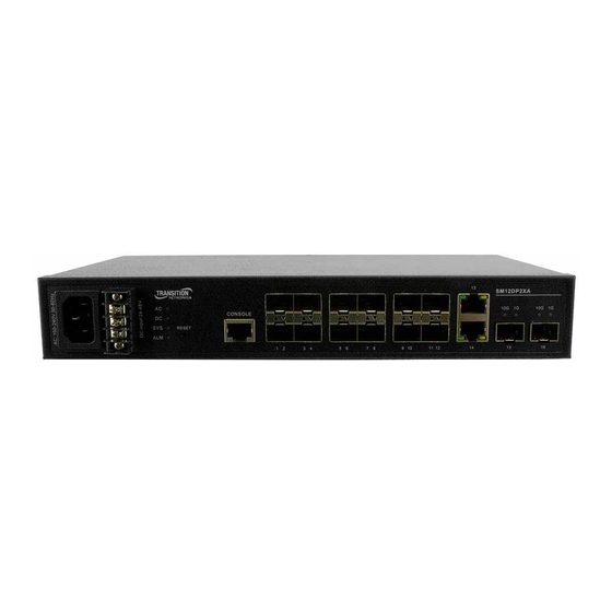
Page 14: Front Panel
Transition Networks SM12DP2XA Install Guide Front Panel The switch front panel contains the power inputs, ports, LEDs and RESET button as shown and described below. 1000BASE‐T Ports The switch contains 10/100/1000BASE‐T RJ‐45 ports. All RJ‐45 ports support automatic MDI/MDI‐X operation, auto‐negotiation and IEEE 802.3x auto‐negotiation of flow control, so the optimum data rate and transmission can be selected automatically. SFP and SFP+ Transceiver Slots The switch supports Small Form Factor Pluggable (SFP) transceiver slots port 1 to port 12, and port 15 to port 16 are 10G SFP+. In the default configuration, if an SFP transceiver (purchased separately) is installed in a slot and has a valid link on the port, the associated RJ‐45 port is disabled. CONSOLE Port The switch has one RJ‐45 CONSOLE port for CLI access via the provided RS232 DB9 to RJ45 Cable. Note that Cross‐over cabling to the CONSOLE port is not supported. 33751 Rev. C https://www.transition.com Page 14 of 32... -
Page 15: Front Panel Leds
Transition Networks SM12DP2XA Install Guide Front Panel LEDs The switch includes a LED panel for system and port indications that simplify installation and network troubleshooting. The LEDs are located on left side of the front panel for easy viewing. The LEDs are shown and described in the tables below. Port Status LEDs LED (Color) View Status Lights when Fiber connection with remote device is good. P1‐P12 SFP Blinks when any traffic is present. Link/Act/Speed The LED is green when linking up 1Gbps. (Green/ Amber) The LED is Amber when linking up 100Mbps. P13‐P14 TP Blinks when any traffic is present. Link/Act/Speed The LED is green when linking up 1Gbps. (Green/ Amber) The LED is Amber when linking up 10/100Mbps. P15‐P16 1G SFP Blinks when any traffic is present. 10G SFP+ The green 10G LED is lit when linked at 10Gbps. Link/Act/Speed The green 1G LED is lit when linked at 1Gbps. System Status LEDs LED (Color) View ... -
Page 16: Rst (Reset) Button
Transition Networks SM12DP2XA Install Guide RST (Reset) Button The front panel RST (Reset) button is recessed for access using a paper clip or something similar. Press and hold the RST (Reset) button for 2‐7 seconds to reset or 7‐12 seconds to restore to factory defaults; the LEDs blink and the fan speeds up momentarily. Press the Reset button for a certain period of time to perform these tasks: Reset the Switch: to reboot and get the switch back to the previous configuration settings saved. Restore the Switch to Factory Defaults: to restore the original factory default settings back to the switch. Note: Based on the table below, you can tell which task is being performed by reading the LED behaviors while pressing the RST (Reset) button. Once the LED behaviors are correctly displayed, you can just release the button. Task Press RST button for SYS LED Behavior Port Status LED Behavior Reset the Switch 2 ~ 7 seconds Blinking Green All LEDs OFF Restore to Defaults 8 ~ 12 seconds Blinking Green All LEDs Stay ON Power Supply Inputs The SM12DP2XA front panel has two front panel power inputs for power redundancy; the switch has a 100~240 VAC power socket for AC power Input and a 24/48VDC power input via the terminal block. Connecting to both AC and DC power provides redundancy (AC with priority). An AC Power Cord is included. To order the corresponding country‐specific power cord, add the extension from ... -
Page 17: Installation
Transition Networks SM12DP2XA Install Guide Installation Site Selection The Switch can be mounted in a standard 19‐inch equipment rack (Via Rack mount Kit). Be sure to follow the guidelines below when choosing a location. The site should: • Be at the center of all the devices you want to link and near a power outlet. • Be able to maintain its temperature within ‐20 to +60°C and its humidity within 5% to 95%, non‐condensing. • Be accessible for installing, cabling and maintaining the devices. • Allow the status LEDs to be clearly visible. Make sure the twisted‐pair Ethernet cable is always routed away from power lines, radios, transmitters or any other electrical interference. Make sure that the Switch is connected to a separate grounded power outlet. Unpacking 1. Carefully unpack all SM12DP2XA contents. 2. Verify receipt of all SM12DP2XA components. Contact your sales representative if any items are missing. 3. Place the SM12DP2XA and related materials near the install location. 4. Save the SM12DP2XA shipping carton and packing materials for possible future use. Unpacking 33751 Rev. C https://www.transition.com Page 17 of 32... -
Page 18: Package Contents
Transition Networks SM12DP2XA Install Guide Package Contents After unpacking the switch, please check the contents to be sure you have received all the components. Before beginning the installation, be sure you have all other necessary installation equipment. • One SM12DP2XA GbE Fiber Managed Switch • Four adhesive rubber feet • Mounting Accessory (for 19” Rack Shelf) • One printed Quick Start Guide • One AC Power Cord • One RS232 DB9 to RJ45 Cable Notify your sales representative immediately if any of the above items is missing or damaged. Mounting The switch can be mounted in a standard 19‐inch equipment rack or on a desktop or shelf as follows. Rack Mounting Before rack mounting the switch, verify these factors: • Temperature: Since the temperature within a rack assembly may be higher than the ambient room temperature, check that the rack‐environment temperature is within the specified operating temperature range (‐20° to +60°C). • Mechanical Loading: Do not place any equipment on top of a rack‐mounted unit. • Circuit Overloading: Be sure that the supply circuit to the rack assembly is not overloaded. • Grounding: Rack‐mounted equipment should be properly grounded. To Rack‐mount Devices: (Optional) 1. Attach the brackets to the device using the screws provided in the Mounting Accessory. ... -
Page 19: Desktop Or Shelf Mounting
Transition Networks SM12DP2XA Install Guide Desktop or Shelf Mounting 1. Attach the four adhesive rubber feet to the bottom of the first switch. 2. Set the device on a flat surface near an AC power source, making sure there are at least two inches of space on all sides for proper air flow. 3. If installing a single switch only, go to “Connecting to a Power Source” at the end of this Chapter. 4. If installing multiple switches, attach four adhesive feet to each one. Place each device squarely on top of the one below, in any order. 33751 Rev. C https://www.transition.com Page 19 of 32... -
Page 20: Ethernet Cabling
Transition Networks SM12DP2XA Install Guide Ethernet Cabling To ensure proper operation when installing the switch into a network, make sure that the current cables are suitable for your operating environment. Check the following criteria against the current installation of your network: • Protection from radio frequency interference emissions. • Electrical surge suppression. • Separation of electrical wires and data based network wiring. • Safe connections with no damaged cables, connectors or shields. WARNING: The mini‐GBICs are Class 1 laser devices. Avoid direct eye exposure to the beam coming from the transmit port. RJ‐45 Connections SFP Transceiver For fiber optic connections, you may use 50/125 or 62.5/125 micron multimode fiber or 9/125 micron single‐mode fiber. For copper connections, you may use unshielded twisted‐pair (UTP) for RJ‐45 connections. For 1G bps connections use Category 5, 5e, 6, or 6A. For 10G bps connections see the table below. The IEEE 802.3an‐2006, Table 55‐12, Cabling Types and Distances provides distance descriptions as follows: Cabling Category Max Link Segment Distance Cabling reference(s) Class E / Category 6 55 m to 100 m* ISO/IEC TR‐24750 / TIA/EIA TSB‐155 Class E / Category 6: unscreened 55 m ... -
Page 21: Installing An Optional Sfp Transceiver
Transition Networks SM12DP2XA Install Guide Installing an Optional SFP Transceiver You can install or remove a mini‐GBIC SFP from a mini‐GBIC slot without having to power off the switch. Refer to the SFP manual for important cautions and warnings. See the Fiber Optics Association (FOA) safety webpage. An optional Gigabit SFP transceiver can be used for a backbone connection between switches, or for connecting to a high‐speed server. Each single‐mode fiber port requires 9/125 micron single‐mode fiber optic cable with an LC connector at both ends. Each multimode fiber optic port requires 50/125 or 62.5/125 micron multimode fiber optic cabling with an LC connector at both ends. Make sure the fiber connectors are clean; see the FOA.org termination cleaning webpage. WARNING: This switch uses lasers to transmit signals over fiber optic cable. The lasers are inherently eye safe in normal operation. However, never look directly at a transmit port when it is powered on. WARNING: When selecting a fiber SFP device, considering safety; make sure that it can function at a temperature that is not less than the recommended maximum operational temperature of the product. You must also use an approved Laser SFP transceiver. NOTE: The mini‐GBIC slots are shared with the four 10/ 100/ 1000Base‐T RJ‐45 ports. If a mini‐GBIC is installed in a slot, the associated RJ‐45 port is disabled and cannot be used The mini‐GBIC ports operate only at full duplex. Half duplex operation is not supported. Ensure the network cable is NOT connected when you install or remove a mini‐GBIC. NOTE: SFP transceivers are not provided in the switch package. See the Transition Networks Optical Devices webpage. Connectivity Rules When adding hubs to your network, note that because switches break up the path for connected devices into separate collision domains, you should not include the switch or connected cabling in your calculations for cascade length involving other devices. ... -
Page 22: To Install An Sfp Transceiver
Transition Networks SM12DP2XA Install Guide To Install an SFP transceiver 1. Consider network and cabling requirements to select an appropriate SFP transceiver type. 2. Remove and keep the LC port’s rubber plug. When not connected to a fiber cable, the rubber plug should be replaced to protect the optics. 3. Make sure the fiber connectors are clean; see http://foa.org/tech/ref/termination/cleaning.html. Dirty fiber terminators on fiber optic cables will impair the quality of the light transmitted through the cable and lead to degraded performance on the port. 4. Insert the transceiver with the optical connector facing outward and the slot connector facing down. Note that SFP transceivers are keyed so they can only be installed in one orientation. 5. Slide the SFP transceiver into the slot until it clicks into place. 6. Connect one end of the cable to the LC port on the switch and the other end to the LC port on the other device. Since LC connectors are keyed, the cable can be attached in only one orientation. 7. As a connection is made, check the Link LED on the switch corresponding to the port to be sure that the connection is valid. The fiber optic ports operate at 1 Gbps. The maximum length for fiber optic cable operating at Gigabit speed will depend on the fiber type. You need an attenuator if the lengths will be less than half the maximum range of your particular optics; see the FOA.org attenuators webpage 33751 Rev. C https://www.transition.com... -
Page 23: Connecting To Power
Transition Networks SM12DP2XA Install Guide Connecting to Power The AC/DC Dual Power Supply can provide power failover when power supplies are connected to different circuits to help reduce network operating risk. With fiber and copper cabling completed, and AC and/or DC power applied, the port LEDs light, the SYS LED flashes, the AC and/or DC LEDs light and the SYS LED goes from flashing to steadily lit. Note: see the Cautions and Warnings on page 3. Connecting to an AC Power Source You can plug or remove the AC power cord through the AC socket from the AC power source. 1. Insert the AC power cord directly into the AC socket located at the front of the switch. 2. Plug the other end of the power cord into a 100‐240 VAC (50‐60Hz) power source. 3. Check the front‐panel LEDs as the device is powered on to be sure the AC LED is lit. If not, check that the power cable is correctly plugged in and that the AC outlet is live. Connecting to a DC Power Source You can plug or remove wires at the terminal block from an external 24/48VDC source. 1. Remove the DC Input cover. –... -
Page 24: Initial Switch Configuration
Transition Networks SM12DP2XA Install Guide Initial Switch Configuration Initial switch configuration can be via CLI or web browser. The factory defaults are IP Address: 192.168.1.77, User Name: admin, and Password: admin. CLI Configuration The command‐line interface (CLI) is a text‐based interface that you can access the CLI through either a direct serial connection to the device or a Telnet session. An‐RJ‐45 cable is used for connecting a terminal or terminal emulator to the SM12DP2XA RJ‐45 port to access the CLI. Attach the RJ‐45 serial port on the switch front panel to the cable for Telnet/CLI configuration. Attach the other end of the DB‐9 cable to a PC running Telnet. See the CLI Reference for initial switch configuration via CLI. Web UI Configuration The left‐hand menu contains two main tabs (Switch and DMS) each with several sub‐tabs for configuring and monitoring the switch’s major functions. The major Switch tab functions include System, Ports, DHCP, Security, Aggregation, Spanning Tree, VLAN, QoS, Diagnostics, and Maintenance. The DMS (Device Management System) functions are DMS Mode, Graphical Monitoring, Management, and Maintenance. See the Web User Guide for initial switch configuration via web browser. 33751 Rev. C https://www.transition.com Page 24 of 32... -
Page 25: Troubleshooting, Warranty, Support And Compliance
Transition Networks SM12DP2XA Install Guide Troubleshooting, Warranty, Support and Compliance General Troubleshooting Most problems are caused by the following situations. Check for these items first when starting troubleshooting: 1. Make sure your switch model supports the feature or function attempted; see Features on page 7. 2. Verify the install process; see Installation on page 17. 3. Troubleshoot connected network devices to pinpoint the problem to the switch. 4. Connecting to devices that have a fixed full‐ duplex configuration. Make sure all devices connected to the Switch devices are configured to auto negotiate, or are configured to connect at half duplex. 5. Faulty or loose cables. Look for loose or obviously faulty connections. If they appear to be OK, make sure the connections are snug. If that does not correct the problem, try a different cable. 6. Check cables. Non‐standard and miswired cables may cause network collisions and other network problems, and can seriously impair network performance. Use a new correctly‐wired cable. A cable tester is a recommended tool for every Ethernet network installation. 7. Check Network Topology to make sure you have a valid network topology. If you no longer experience the problems, the new topology is probably at fault. Also, make sure your network topology contains no data path loops. 8. Check port configurations. A port on your Switch may not be operating as you expect because it has been put into a “blocking” state by Spanning Tree, GVRP (automatic VLANs), or LACP (automatic trunking). Note that the normal operation of the Spanning Tree, GVRP, and LACP features may put the port in a blocking state. Make sure the port was not configured as disabled via software. 9. SYS LED is Off. Check connections between the switch, the power cord and the wall outlet. Contact Tech Support for assistance. See LED Troubleshooting below. 10. Link LED is Off. Verify that the switch and attached device are powered on. Be sure the cable is plugged into the switch and corresponding device. If the switch is installed in a rack, check the connections to the punch‐down block and patch panel. Verify that the proper cable type is used and its length does not exceed ... -
Page 26: Led Troubleshooting
Transition Networks SM12DP2XA Install Guide LED Troubleshooting The LED behavior is summarized below. LED Color Function Lit Green when Power A on Switch is Ready. POWER/Alarm Green/Red Lit Red when FAN, Temperature or Voltage Detected Fault Global Blinks when POST Running Link/Act/Speed Green Lit Green when select to Link/Act/Speed mode. Light off: port disconnected or link failed. Green Light on: 1GLink Present, No Activity. SFP Green/ Link/Act/Speed Amber Light on: 100M Link Present, No Activity. Ports 1‐12 Amber Green Blinking : 1GActivity. Port is sending or receiving data. Amber Blinking : 100M Activity. Port is sending or receiving data. LNK: Amber/Green (Two Color) Light off: port disconnected or link failed RJ45 Green/ Link/Act/,Speed ... -
Page 27: Recording Device And System Information
Transition Networks SM12DP2XA Install Guide Recording Device and System Information After performing the troubleshooting procedures, and before calling or emailing Technical Support, please record as much information as possible in order to help the Transition Networks Tech Support Specialist. 1. Select the SM12DP2XA Configuration > System > Information menu path. From the CLI, use the show commands needed to gather the information below or as requested by the TN Support Specialist. 2. Record SM12DP2XA Model Information: Model Name: _________________________________________ Hardware Version: __________________________ Mechanical Version: _____________________________ Firmware Version: ___________________________System Date: ___________________________________ 3. Record the LED Status: _____________________________________________________________________ ________________________________________________________________________________________ 4. Provide additional information to your Tech Support Specialist. See the “Troubleshooting” section above. Your Transition Networks service contract number: _________________________________________________ Describe the failure: _________________________________________________________________________ ___________________________________________________________________________________________ ___________________________________________________________________________________________ Describe any action(s) already taken to resolve the problem (e.g., changing mode, rebooting, etc.): ___________________________________________________________________________________________ ___________________________________________________________________________________________ ___________________________________________________________________________________________ The serial and revision numbers of all involved Transition Networks products in the network: _______________ ___________________________________________________________________________________________ ___________________________________________________________________________________________ Describe your network environment (layout, cable type, etc.): _______________________________________ ___________________________________________________________________________________________ ___________________________________________________________________________________________ ___________________________________________________________________________________________ Network load and frame size at the time of trouble (if known): ________________________________________ ... - Page 28 Transition Networks SM12DP2XA Install Guide Limited Lifetime Warranty To return a defective product for warranty coverage, contact Transition Networks’ technical support department for a return authorization number. Contact Us Technical Support Technical support is available 24‐hours a day US and Canada: 1‐800‐260‐1312 International: 00‐1‐952‐941‐7600 Main Office tel: +1.952.941.7600 | toll free: 1.800.526.9267 | fax: 952.941.2322 sales@transition.com | techsupport@transition.com | customerservice@transition.com Address Transition Networks 10900 Red Circle Drive Minnetonka, MN 55343, U.S.A. Firmware: Keep your products up to date by downloading the latest firmware. You must log in or create an account to download firmware. For further assistance contact us at +1.952.358.3601, 1.800.260.1312, or at techsupport@transition.com. 33751 Rev. C https://www.transition.com Page 28 of 32...
- Page 29 Transition Networks SM12DP2XA Install Guide Compliance Information FCC Regulations This equipment has been tested and found to comply with the limits for a Class A digital device, pursuant to part 15 of the FCC rules. These limits are designed to provide reasonable protection against harmful interference when the equipment is operated in a commercial environment. This equipment generates, uses, and can radiate radio frequency energy and, if not installed and used in accordance with the instruction manual, may cause harmful interference to radio communications. Operation of this equipment in a residential area is likely to cause harmful interference, in which case the user will be required to correct the interference at the user's own expense. This device complies with part 15 of the FCC Rules. Operation is subject to the following two conditions: (1) This device may not cause harmful interference, and (2) this device must accept any interference received, including interference that may cause undesired operation. You are cautioned that changes or modifications not expressly approved by the party responsible for compliance could void your authority to operate the equipment. Canadian Regulations This digital apparatus does not exceed the Class A limits for radio noise for digital apparatus set out on the radio interference regulations of the Canadian Department of Communications. Le présent appareil numérique n'émet pas de bruits radioélectriques dépassant les limites applicables aux appareils numériques de la Class A prescrites dans le Règlement sur le brouillage radioélectrique édicté par le ministère des Communications du Canada. Declaration of Conformity (DoC) 33751 Rev. C https://www.transition.com Page 29 of 32...
- Page 30 Transition Networks SM12DP2XA Install Guide High Risk Activities Disclaimer Components, units, or third‐party products used in the product described herein are NOT fault‐tolerant and are NOT designed, manufactured, or intended for use as on‐line control equipment in the following hazardous environments requiring fail‐safe controls: the operation of Nuclear Facilities, Aircraft Navigation or Aircraft Communication Systems, Air Traffic Control, Life Support, or Weapons Systems ("High Risk Activities"). Transition Networks and its supplier(s) specifically disclaim any expressed or implied warranty of fitness for such High Risk Activities. Notices : The information in this user’s guide is subject to change. For the most current SISTG10xx‐211‐LRT‐B information refer to the online user guide at https://www.transition.com. Product is certified by the manufacturer to comply with DHHS Rule 21/CFR, Subchapter J applicable at the date of manufacture. Notices: Not Designed for Use in Life Support Equipment or Applications: These products are not designed for use in life support equipment or applications that would cause a life‐threatening situation if any such product failed. Do not use this product in these types of equipment or applications. ERN # : ERN # (Encryption Registration Number) R111839 (self‐declaring). IMPORTANT Copper based media ports: e.g., Twisted Pair (TP) Ethernet, USB, RS‐232, RS422, RS485, DS1, DS3, Video Coax, etc., are intended to be connected to intra‐building (inside plant) link segments that are not subject to lightening transients or power faults. Copper based media ports: e.g., Twisted Pair (TP) Ethernet, USB, RS‐232, RS‐422, RS‐485, DS1, DS3, Video Coax, etc., are NOT to be connected to inter‐building (outside plant) link segments that are subject to lightening transients or power faults. Failure to observe this caution could result in damage to equipment. Warning: Visible and invisible laser radiation when open: Do not stare into the beam or view the beam directly with optical instruments. Failure to observe this warning could result in an eye injury or blindness. WARNING: Use of controls, adjustments or the performance of procedures other than those specified herein may result in hazardous radiation exposure. 33751 Rev. C https://www.transition.com Page 30 of 32...
- Page 31 Transition Networks SM12DP2XA Install Guide Electrical Safety Warnings Electrical Safety IMPORTANT: This equipment must be installed in accordance with safety precautions. Elektrische Sicherheit WICHTIG: Für die Installation dieses Gerätes ist die Einhaltung von Sicherheitsvorkehrungen erforderlich. Elektrisk sikkerhed VIGTIGT: Dette udstyr skal installeres i overensstemmelse med sikkerhedsadvarslerne. Elektrische veiligheid BELANGRIJK: Dit apparaat moet in overeenstemming met de veiligheidsvoorschriften worden geïnstalleerd. Sécurité électrique IMPORTANT: Cet équipement doit être utilisé conformément aux instructions de sécurité. Sähköturvallisuus TÄRKEÄÄ: Tämä laite on asennettava turvaohjeiden mukaisesti. Sicurezza elettrica IMPORTANTE: questa apparecchiatura deve essere installata rispettando le norme di sicurezza. Elektrisk sikkerhet VIKTIG: Dette utstyret skal installeres i samsvar med sikkerhetsregler. Segurança eléctrica IMPORTANTE: Este equipamento tem que ser instalado segundo as medidas de precaução de segurança. Seguridad eléctrica IMPORTANTE: La instalación de este equipo deberá llevarse a cabo cumpliendo con las precauciones de seguridad. Elsäkerhet OBS! Alla nödvändiga försiktighetsåtgärder måste vidtas när denna utrustning används. 33751 Rev. C https://www.transition.com Page 31 of 32...
- Page 32 Transition Networks SM12DP2XA Install Guide Transition Networks 10900 Red Circle Drive Minnetonka, MN 55343, U.S.A. tel: +1.952.941.7600 | toll free: 1.800.526.9267 | fax: 952.941.2322 sales@transition.com | techsupport@transition.com | customerservice@transition.com Copyright © 2018 Transition Networks. All rights reserved. Printed in the U.S.A. SM12DP2XA Install Guide, 33751 Rev. C 33751 Rev. C https://www.transition.com Page 32 of 32...
Need help?
Do you have a question about the SM12DP2XA and is the answer not in the manual?
Questions and answers