Table of Contents
Advertisement
Quick Links
Advertisement
Table of Contents

Related Manuals for INVT Goodrive300-21 Series


Summary of Contents for INVT Goodrive300-21 Series
- Page 1 Goodrive300-21 Series Dual-inverter Integrated Machine for Air Compressor...
- Page 2 Goodrive300-21 integrated machine for air compressor Preface Preface Goodrive300-21 series dual inverter integrated machine for air compressor (hereafter referred to as GD300-21 compressor integrated machine) especially developed synchronous/asynchronous twin screw air compressor. It can be used in combination with HMI touch screen to drive and control the twin screw air compressor.
-
Page 3: Table Of Contents
Goodrive300-21 integrated machine for air compressor Contents Contents Preface ............................i Contents ............................ii 1 Product overview ........................1 1.1 Product specifications ......................1 1.2 Product nameplate ......................2 1.3 Model instruction ......................... 3 1.4 Product ratings ........................3 2 Installation guidance ........................5 2.1 Wiring and terminal instruction of main circuit .............. - Page 4 Goodrive300-21 integrated machine for air compressor Contents B.1.2 Electrical wiring ....................... 81 B.1.3 Fuse pedestal installation ..................82 B.1.4 Dimension of contactor component ................. 83 B.2 IoT module ........................84 B.2.1 Product overview ....................84 B.2.2 Specifications ......................88 B.2.3 Operation guide ...................... 89 B.2.4 Ordering information ....................
-
Page 5: Product Overview
Goodrive300-21 integrated machine for air compressor Product overview 1 Product overview GD300-21 air compressor integrated machine is capable of providing dual inverter output of master and fan for the air compressor as well as offering +24V power to the touch screen. It supports control of solenoid valve and receiving of temperature and pressure signal. -
Page 6: Product Nameplate
1.2 Product nameplate IP20 Model:GD300-21-022G-4 Power(Output):22kW(motor) 1kW(fan) Input:AC 3PH 380V(-15%)-440V(+10%) 45A 47Hz-63Hz Output:AC 3PH 0V-Uinput 45A 0Hz-400Hz(motor) AC 3PH 0V-Uinput 3A 0Hz-50Hz(fan) S/N: MADE IN CHINA Shenzhen INVT Electric Co.,Ltd Figure 1-1 Product nameplate... -
Page 7: Model Instruction
Goodrive300-21 integrated machine for air compressor Product overview Note: The preceding are standard product nameplate examples. The CE/TUV/IP20 marking on the top right will be marked according to actual certification conditions. 1.3 Model instruction A model designation code contains product information. You can find the model designation code on the inverter nameplate and simplified nameplate. - Page 8 Goodrive300-21 integrated machine for air compressor Product overview Main motor inverter Fan inverter Rated input current Rating Rated Rating Rated Model of the integrated output output output output machine (A) power (kW) current (A) power (kW) current (A) GD300-21-075G-4 GD300-21-090G-4 Note: ...
-
Page 9: Installation Guidance
Goodrive300-21 integrated machine for air compressor Installation guidance 2 Installation guidance 2.1 Wiring and terminal instruction of main circuit 2.1.1 Wiring diagram of the main circuit Master Goodrive300-21 Figure 2-1 Wiring diagram of the main circuit 2.1.2 Terminal diagram of the main circuit The terminal layout of 15–22kW, 30kW–37kW and 45–90kW main circuit slightly differs from each other. - Page 10 Goodrive300-21 integrated machine for air compressor Installation guidance Figure 2-3 AC380V 45–90kW Table 2-1 Terminal instruction Symbol Description UA, UB, UC Used for input connection of optional contactor components. R, S, T 3PH AC input terminals, connecting to the grid U1, V1, W1 3PH AC output terminal, connected to main motor of air compressor U2, V2, W2...
-
Page 11: Wiring And Terminal Instruction Of Control Circuit
Goodrive300-21 integrated machine for air compressor Installation guidance 2.2 Wiring and terminal instruction of control circuit 2.2.1 Control circuit layout diagram 34PIN CN17 26PIN Goodrive300-21 control board CN15 +24V +24V 485+ CN14-5 485- CGND CN10 CN11 CN12 CN13 CN14 Figure 2-4 Control circuit layout diagram Table 2-2 Terminal instruction Symbol Name... - Page 12 Goodrive300-21 integrated machine for air compressor Installation guidance Symbol Name Remarks 110V voltage selection Select this terminal with jumpers when users select the terminal solenoid valve with 110V coil or the contactor. Access terminal for 485 485 corresponds to access terminal resistor. Does not communication terminal connect terminal resistor by default.
-
Page 13: Wiring Diagram Of Control Circuit
Goodrive300-21 integrated machine for air compressor Installation guidance 2.2.2 Wiring diagram of control circuit Remote data collection terminal (Optional) RS485 joint control GD300-21 RS485 control board CN17 GD300-21 control board Pressure sensor PT100 temperature Output voltage interface sensor interface Multi-function terminal 220/110VAC 24V 4-20mA Solenoid... - Page 14 Goodrive300-21 integrated machine for air compressor Installation guidance Category Symbol Terminal name Description input analog signal 1 4–20mA/2–10V corresponds to 0–1.6MPa; P1 is switched by jumper J7 while P2 by J8 2. Input impedance: 20kΩ for voltage input; Pressure 500Ω for current input analog signal 2 3.
-
Page 15: Instruction For Panel Display
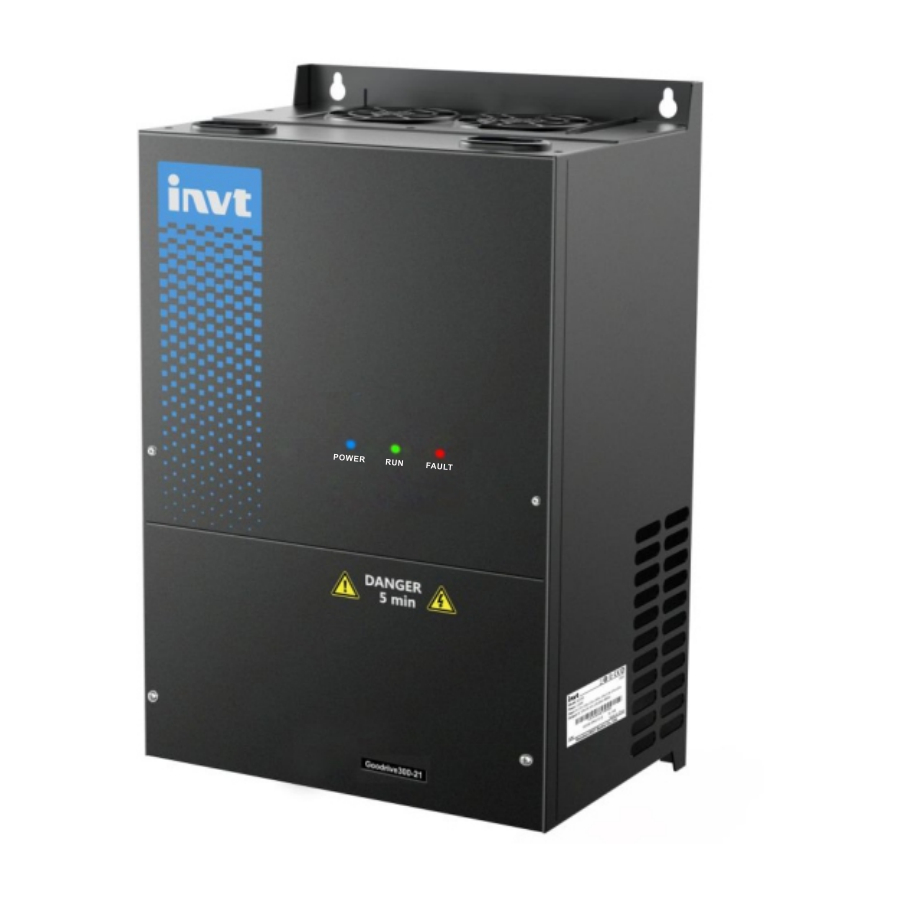
Goodrive300-21 integrated machine for air compressor Instruction for panel display 3 Instruction for panel display The panel of GD300-21 series air compressor integrated machine carries three LED indicators (fault, running, power). The position and display state of the indicators are illustrated as below: Power Fault Figure 3-1 Diagram of indicator position... -
Page 16: Commissioning Guidelines
Goodrive300-21 integrated machine for air compressor Commissioning guidelines 4 Commissioning guidelines 4.1 Wiring diagram of integrated machine system Remote data collection GD300-21 terminal (optional) 485B+ 485+ 485A+ 485- 485A- 485B- +24V RS485 RS485 joint control E-stop Customized Internal fault input signal signal output Oil gas temp. - Page 17 Goodrive300-21 integrated machine for air compressor Commissioning guidelines AC power Main motor R, S, T, ground wire through hole U1, V1, W1, ground wire through hole Through-hole of Through-hole of controlling cable controlling cable Through-hole of U2, V2, W2, ground wire through hole optional parts cable Ventilation hole at the bottom of integrated machine...
- Page 18 Goodrive300-21 integrated machine for air compressor Commissioning guidelines AC power Main motor U1, V1, W1 through R, S, T through hole hole Through hole of Through hole of controlling cable controlling cable Through hole of optional parts U2, V2, W2, ground wire cable through hole Through hole of...
-
Page 19: Function Commissioning Procedure
Goodrive300-21 integrated machine for air compressor Commissioning guidelines Note: There are two controlling cable through holes on the top and at the bottom of the integrated machine cabinet, users can select which through-hole to use based on wiring condition. It is recommended that the controlling cable is routed via top through-hole to realize separation between controlling cable and motor cable and reduce interference. - Page 20 Goodrive300-21 integrated machine for air compressor Commissioning guidelines 3. Click "Enter" to enter the working environment interface, as shown in the following figure: Figure 4-7 Working interface 4. Click "MENU" in above interface and the interface is as follows: Figure 4-8 Menu interface...
- Page 21 Goodrive300-21 integrated machine for air compressor Commissioning guidelines 5. Click "System configuration" in touch screen menu to enter the system configuration page, as shown in the following figure: Figure 4-9 System configuration interface The fan inverter is enabled by default. Debug according to the debugging procedures. Step 1 Click "Motor parameter setting"...
- Page 22 Goodrive300-21 integrated machine for air compressor Commissioning guidelines Figure 4-11 Main (asynchronous) motor parameters setting interface Step 2 After setting motor parameters according to actual motor nameplate parameters, click "Autotun" and after recognition completes, click "Next" and set fan motor parameter (Max. frequency, Rated power, Rated frequency, Rated voltage, Rated current and Rated rotation speed are required.) Figure 4-12 Fan motor parameters setting interface Step 3 In system configuration interface, click "One button setting"...
- Page 23 Goodrive300-21 integrated machine for air compressor Commissioning guidelines Function code Configuration value Description 0: Vector control (SM) P00.00 0 or 2 2: VF control (AM) Select according to the motor type. P00.01 2: Communication P00.06 Main frequency PID control setting P01.15 35.00 Stop frequency: 35Hz...
- Page 24 Goodrive300-21 integrated machine for air compressor Commissioning guidelines Step 5 In system configuration interface, click “Debug mode” and the interface is shown as follows: Figure 4-14 Debugging mode interface Click "Jog run" for motor and fan to determine motor rotation direction; click "Load" or "Unload" to test the action of solenoid valve.
- Page 25 Goodrive300-21 integrated machine for air compressor Commissioning guidelines 7. Click "Maintenance parameters" in touch screen menu and the interface is shown as follows: Figure 4-16 Maintenance parameter interface 8. Click "Protection parameters" in the menu and the interface is shown as follows: Figure 4-17 Protection parameter interface...
- Page 26 Goodrive300-21 integrated machine for air compressor Commissioning guidelines 9. Click “Running information” in the menu and the interface is shown as follows: Figure 4-18 Running information interface 10. After adjusting user parameter, factory parameter, maintenance parameter according to touch screen manual, return to the working interface and click “RUN” to run. Note: All the parameters displayed in 4.3 Function commissioning procedure are for reference only and subject to actual displayed content.
-
Page 27: Function Description
Goodrive300-21 integrated machine for air compressor Function description 5 Function description "○" indicates that the value of the parameter can be modified when the inverter is in stopped or running state. "◎" indicates that the value of the parameter cannot be modified when the inverter is in running state. "●"... - Page 28 Goodrive300-21 integrated machine for air compressor Function description Function Name Description Default Modify code 9–11: Reserved Note: A frequency and B frequency cannot be set to the same frequency reference mode. Frequency source can be set by P00.09. Reference object of 0: Max.
- Page 29 Goodrive300-21 integrated machine for air compressor Function description Function Name Description Default Modify code 7: Parameter 1 for customer 1 8: Parameter 2 for customer 1 9: Parameter for customer 2 10: Parameter for customer 3 Note: When the factory setting is restored, the motor parameters in group P02 keep the current value unchanged.
- Page 30 Goodrive300-21 integrated machine for air compressor Function description Function Name Description Default Modify code Leakage inductance Model ○ P02.08 0.1–6553.5mH of AM 1 depended Mutual inductance Model ○ P02.09 0.1–6553.5mH of AM 1 depended No-load current of Model ○ P02.10 0.1–6553.5A AM 1 depended...
- Page 31 Goodrive300-21 integrated machine for air compressor Function description Function Name Description Default Modify code 0: No protection Common motor (with low-speed Overload protection ◎ P02.26 compensation) of motor 1 Frequency-variable motor (without low-speed compensation) Motor overload multiples M=Iout/(In*K) “In” is rated motor current, “Iout” is inverter output current, “K”...
- Page 32 Goodrive300-21 integrated machine for air compressor Function description Function Name Description Default Modify code Low-point frequency ○ P03.02 0.00Hz–P03.05 5.00Hz for switching Speed-loop ○ P03.03 0–200.0 20.0 proportional gain 2 Speed-loop integral ○ P03.04 0.000–10.000s 0.200s time 2 High-point ○ P03.05 frequency for P03.02–P00.03 (Max.
- Page 33 Goodrive300-21 integrated machine for air compressor Function description Function Name Description Default Modify code Electromotive ○ P03.20 torque upper limit 0.0–300.0% (of the motor rated current) 180.0% set through keypad Braking torque ○ P03.21 upper limit set 0.0–300.0% (of the motor rated current) 180.0% through keypad Weakening...
- Page 34 Goodrive300-21 integrated machine for air compressor Function description Function Name Description Default Modify code V/F frequency point ○ P04.05 P04.03–P04.07 00.00Hz 2 of motor 1 V/F voltage point 2 ○ P04.06 0.0%–110.0% (of the rated voltage of motor 1) 00.0% of motor 1 V/F frequency point P04.05–P02.02 (Rated frequency of motor 1)
- Page 35 Goodrive300-21 integrated machine for air compressor Function description Function Name Description Default Modify code ◎ P05.05 Function of S5 4: Jog forward 5: Jog reversely 6: Coast to stop 7: Reset faults 8: Pause running 9: External fault input 10–24: Reserved 25: Pause PID control 26–39: Reserved 40: Clear electricity consumption...
- Page 36 Goodrive300-21 integrated machine for air compressor Function description Function Name Description Default Modify code ○ P05.18 S3 switch-on delay 0.000–50.000s 0.000s ○ P05.19 S3 switch-off delay 0.000–50.000s 0.000s ○ P05.20 S4 switch-on delay 0.000–50.000s 0.000s ○ P05.21 S4 switch-off delay 0.000–50.000s 0.000s ○...
- Page 37 Goodrive300-21 integrated machine for air compressor Function description Function Name Description Default Modify code Mapping settings P05.40 Mapping percentage P05.38 Input voltage P18.28 17.20 P18.29 ○ P05.41 PT1 input filter time 0.000s–10.000s 0.300s ○ P05.42 P2 lower limit 0.00V–P05.44 2.00V Corresponding ○...
- Page 38 Goodrive300-21 integrated machine for air compressor Function description Function Name Description Default Modify code 12: Ready for running 13: Pre-exciting 14–19: Reserved 20: External fault is valid 21–22: Reserved 23: Modbus communication virtual terminal output 24–25: Reserved 26: Special for oil pump (for blower) 27: Auxiliary motor start/stop control (for air compressor) 28: Solenoid valve control output (for air...
- Page 39 Goodrive300-21 integrated machine for air compressor Function description Function Name Description Default Modify code ○ P07.00 User password 0–65535 0: No operation 1: Upload parameters from the local address to the keypad 2: Download parameters (including motor parameters) from the keypad to the local address 3: Download parameters (excluding groups P02 and P12) from the keypad to the local...
- Page 40 Goodrive300-21 integrated machine for air compressor Function description Function Name Description Default Modify code Inverter rated ● P07.19 50–1200V voltage Inverter rated ● P07.20 0.1–6000.0A current ● P07.21 Factory bar code 1 0x0000–0xFFFF ● P07.22 Factory bar code 2 0x0000–0xFFFF ●...
- Page 41 Goodrive300-21 integrated machine for air compressor Function description Function Name Description Default Modify code 25: Electronic overload (OL3) 26: Keypad communication error (PCE) 27: Parameter upload error (UPE) 28: Parameter download error (DNE) 29–31: Reserved 32: To-ground short-circuit fault 1 (ETH1) 33: To-ground short-circuit fault 2 (ETH2) 34: Speed deviation fault (dEu) 35: Mal-adjustment fault (STo)
- Page 42 Goodrive300-21 integrated machine for air compressor Function description Function Name Description Default Modify code Output voltage at ● P07.43 last fault Output current at ● P07.44 0.0A last fault Bus voltage at last ● P07.45 0.0V fault Max. temperature at ●...
- Page 43 Goodrive300-21 integrated machine for air compressor Function description Function Name Description Default Modify code Delay time of ○ P08.18 0.0–6000.0s 60.0s automatic start-up Low voltage ○ P08.19 frequency-limit 0.0–6000.0s 60.0s running time 0–1 Counting mode of ○ P08.26 0: Counting during motor running maintenance time 1: Counting during motor running and sleeping 0: Keypad (P09.01)
- Page 44 Goodrive300-21 integrated machine for air compressor Function description Function Name Description Default Modify code increase to balance the PID. Example: PID control on strain during unwinding. P determines the strength of the whole PID adjuster. The larger the value of P, the stronger the adjustment intensity.
- Page 45 Goodrive300-21 integrated machine for air compressor Function description Function Name Description Default Modify code indicates slower response. Setting range: 0.001–10.000s The feedback value of the PID system is relative to the max. deviation of the closed loop reference. The PID regulator stops PID control ○...
- Page 46 Goodrive300-21 integrated machine for air compressor Function description Function Name Description Default Modify code LED tens place: 0: Output phrase loss protection disabled 1: Output phrase loss protection enabled LED hundreds place: 0: Hardware protection against input phrase loss disabled 1: Hardware protection against input phrase loss enabled Note: The hundreds place of the LED detects...
- Page 47 Goodrive300-21 integrated machine for air compressor Function description Function Name Description Default Modify code 1: Do not act upon an undervoltage fault LED tens place: 0: Act during automatic reset 1: Do not act during the automatic reset period Speed deviation ○...
- Page 48 Goodrive300-21 integrated machine for air compressor Function description Function Name Description Default Modify code Valid when the motor speed exceeds the rated High frequency speed. If oscillation occurred to the motor, ○ P13.12 compensation 50.0% adjust this parameter properly. coefficient Setting range: 0.0–100.0% Local ○...
- Page 49 Goodrive300-21 integrated machine for air compressor Function description Function Name Description Default Modify code Communication ○ P14.07 address of auxiliary 1–247; 0 indicates a broadcast address Auxiliary pressure 0: Disable ◎ P15.00 start-up protection 1: Enable 0.00–20.00MPa Auxiliary pressure The inverter cannot start if current auxiliary ○...
- Page 50 Goodrive300-21 integrated machine for air compressor Function description Function Name Description Default Modify code Delay time of 0–65535s ○ P15.06 auxiliary pressure Note: The value 0 indicates that the low detection auxiliary pressure fault will not be detected. 0.00–20.00MPa When the auxiliary pressure protection is enabled (P18.39=1) and the auxiliary pressure Auxiliary pressure ○...
- Page 51 Goodrive300-21 integrated machine for air compressor Function description Function Name Description Default Modify code ● P17.07 Exciting current -3000.0–3000.0A 0.0A -300.0% –300.0% (of the motor rated power) ● P17.08 Motor power 0.0% ● P17.09 Output torque -250.0–250.0% 0.0% Estimated motor ●...
- Page 52 Goodrive300-21 integrated machine for air compressor Function description Function Name Description Default Modify code Displays the analog input voltage value of PT2 channel. Connect PT100 thermal resistor temperature sensor in air compressor mode, and different resistance value will be generated under different temperature. Different resistance value corresponds to ●...
- Page 53 Goodrive300-21 integrated machine for air compressor Function description Function Name Description Default Modify code Auto-sleep mode Current pressure P18.05 P18.07 P18.06 Load Time Current running frequency P00.04 P18.12 P18.13 P01.15 Time Sleep trigger Sleep stop Manual sleep mode Manual sleep command Enable Time...
- Page 54 Goodrive300-21 integrated machine for air compressor Function description Function Name Description Default Modify code inverter will carry out loading operation again and pressure PID will regulate accordingly. Manual: set through touch screen or other communication methods 0: Automatic 1: Manual In manual mode, loading/unloading is conducted manually via touch screen or other Loading/unloading...
- Page 55 Goodrive300-21 integrated machine for air compressor Function description Function Name Description Default Modify code master is controlled by pressure PID. The system keeps exhaust pressure constant by adjusting the rotation speed of the master. Refer to section 5.2 for process logic of pressure control.
- Page 56 Goodrive300-21 integrated machine for air compressor Function description Function Name Description Default Modify code time set by P18.14 and then it stops. Setting range: 0–3600s Loading operation can only be available after Delay time of the master runs at no-load frequency by the ○...
- Page 57 Goodrive300-21 integrated machine for air compressor Function description Function Name Description Default Modify code It determines the adjustment intensity of temperature PID regulator. The larger the kp, the stronger the intensity, however, too strong the intensity may cause temperature ○ P18.24 18.0 Gain coefficient (kp)
- Page 58 Goodrive300-21 integrated machine for air compressor Function description Function Name Description Default Modify code 0.00Hz–10.00Hz Reduction rate of It is the reduction quantity of the ○ P18.31 upper limit corresponding upper limit frequency for each 0.00Hz frequency additional 0.01Mpa when current pressure is larger than P18.30.
- Page 59 Goodrive300-21 integrated machine for air compressor Function description Function Name Description Default Modify code 0.00–20.00Mpa It is related to actual range of pressure sensor. Upper limit of ◎ P18.38 The voltage corresponds to P18.04 is P05.44. 1.60Mpa pressure sensor P2 Note: This value stays in current set value during restoring to factory value.
- Page 60 Goodrive300-21 integrated machine for air compressor Function description Function Name Description Default Modify code ensure the running current of the master will not exceed automatic frequency reduction threshold. 0–8000h When this parameter is set to "0", the maintenance time-out function is invalid. If it is Time-out time of set to non-zero value, then the system will ○...
- Page 61 Goodrive300-21 integrated machine for air compressor Function description Function Name Description Default Modify code Current pressure Mpa P18.37=0 P18.04 P19.11 P1 input P05.32 P17.19 P05.34 voltage Current pressure Mpa P18.37=1 P18.38 P19.11 P2 input voltage P05.42 P17.21 P05.44 Range: 0.00–655.35Mpa Displays the head temperature currently detected.
- Page 62 Goodrive300-21 integrated machine for air compressor Function description Function Name Description Default Modify code 1: Fault; 0: normal BIT4: External fault signal 1 1: Fault; 0: normal BIT5: External fault signal 2 1: Fault; 0: normal BIT6: Solenoid valve signal state 1: Load;...
- Page 63 Goodrive300-21 integrated machine for air compressor Function description Function Name Description Default Modify code 1: Pressure pre-alarm; 0: normal BIT8: Auxiliary temperature pre-alarm signal 1: Temperature pre-alarm; 0: normal BIT9: Auxiliary pressure alarm signal 1: Pressure alarm; 0: normal BIT10: Auxiliary temperature alarm signal 1: Temperature pre-alarm;...
- Page 64 Goodrive300-21 integrated machine for air compressor Function description Function Name Description Default Modify code It displays the auxiliary pressure value detected currently. Current pressure Mpa P18.37=0 P18.04 P19.11 Current auxiliary ● P19.20 0.00Mpa P1 input P05.32 P17.19 P05.34 pressure voltage Current pressure Mpa P18.37=1 P18.38...
-
Page 65: Air Compressor Control Logic
Goodrive300-21 integrated machine for air compressor Function description Function Name Description Default Modify code 1: Negative sequence 2: R-phase loss 3: S-phase loss 4: T-phase loss 5.2 Air compressor control logic (1) The control logic of air compressor is shown as below: Stand-by Starting command... - Page 66 Goodrive300-21 integrated machine for air compressor Function description (2) The pressure and running frequency control of air compressor during running is shown as below: Current pressure P18.05 P18.07 P18.06 Time Load valve Current running frequency P00.04 P18.11 P18.12 P18.15 P18.13 P18.15 P18.14 P01.15...
-
Page 67: Pid Commissioning
Goodrive300-21 integrated machine for air compressor Function description H: Restart delay stage after stop, the duration time is P18.16 In automatic loading/unloading mode, when air compressor control is valid and air supply of the compressor becomes normal after it starts, if exhaust pressure is detected to be above P18.05, automatic unloading will be applied. -
Page 68: General Procedures For Pid Parameter Setup
Goodrive300-21 integrated machine for air compressor Function description Introduction to the working principles and control methods for PID control: Proportional control (Kp): When the feedback is different from the reference, the output will be proportional to the difference. If such a difference is constant, the regulating variable will also be constant. Proportional control can respond to feedback changes rapidly, however, it cannot eliminate the difference by itself. -
Page 69: How To Fine-Tune Pid
Goodrive300-21 integrated machine for air compressor Function description b. Determine integral time Ti After proportional gain P is determined, set the initial value of integral time Ti to a large value, and decrease Ti gradually until system oscillation occurs. Then in reverse, increase Ti until system oscillation disappears. - Page 70 Goodrive300-21 integrated machine for air compressor Function description Control long-term vibration: If the cycle of periodic vibration is longer than the set value of integral time (Ti), it indicates the integral action is too strong, prolong the integral time (Ti) to control vibration. Response Before adjustment After adjustment...
- Page 71 Goodrive300-21 integrated machine for air compressor Function description Function Name Description Default code 0: Analog P1-feedback 1: Reserved 2: Analog P2-feedback PID feedback 3: Reserved P09.02 source 4: Modbus communication 5–7: Reserved 8: Pressure feedback for air compressor-specific function 0: PID output is positive. When the feedback signal is greater than the PID reference value, the output frequency of the inverter will decrease to balance the PID.
- Page 72 Goodrive300-21 integrated machine for air compressor Function description Function Name Description Default code Used to determine the strength of the change ratio adjustment on the deviation of PID feedback and reference from the PID regulator. If feedback quantity changes 100% during this time period, the range within which the differential regulator Differential time P09.06...
-
Page 73: Running Logic Of Blower Oil Pump
Goodrive300-21 integrated machine for air compressor Function description Function Name Description Default code 0: Limit as per the max. frequency 1: Limit as per A frequency Thousands place: 0: A+B frequency. Acceleration /deceleration of main reference A frequency source buffering is invalid. -
Page 74: Troubleshooting
Goodrive300-21 integrated machine for air compressor Troubleshooting 6 Troubleshooting 6.1 Faults and countermeasures for integrated machine Table 6-1 Faults and countermeasures Fault Fault type Possible cause Solution code Inverter unit U-phase ACC is too fast; OUt1 Increase ACC time; protection IGBT module is damaged;... - Page 75 Goodrive300-21 integrated machine for air compressor Troubleshooting Fault Fault type Possible cause Solution code restarted; Check the grid voltage; The voltage of the grid is too Select the inverter with larger low; power; Load is too large. Select a proper motor. Phase loss violent...
- Page 76 Goodrive300-21 integrated machine for air compressor Troubleshooting Fault Fault type Possible cause Solution code Error in reading or writing EEPROM operation Press STOP/RST to reset; control parameters. fault Replace the main control board. The EEPROM is damaged. PID feedback offline; Check PID feedback signal PID feedback offline PIDE...
- Page 77 Goodrive300-21 integrated machine for air compressor Troubleshooting Fault Fault type Possible cause Solution code Check whether the motor wiring Inverter output short is normal/the motor is short To-ground connected to the ground; circuited to the ground; ETH2 short-circuit fault 2 There is a fault in the current Replace the hall component;...
-
Page 78: Faults And Countermeasures For Air Compressor Device
Goodrive300-21 integrated machine for air compressor Troubleshooting 6.2 Faults and countermeasures for air compressor device Fault and countermeasures for air compressor device are listed as below: P19.13 Status type Possible cause Solution BIT0=1 Air filter is blocked Air filter is abnormal. Stop and check the air filter BIT1=1 Oil filter is blocked Oil filter is abnormal. - Page 79 Goodrive300-21 integrated machine for air compressor Troubleshooting P19.13 Status type Possible cause Solution Temperature detection circuit is abnormal. Temperature detection sensor is abnormal; Temperature detection input actual temperature circuit is abnormal; Low temperature detected by PT1 is less than BIT14=1 The actual temperature is too protection pre-alarm the low temperature protection...
- Page 80 Goodrive300-21 integrated machine for air compressor Troubleshooting P19.14 Status type Possible cause Solution Check if pressure detection sensor actual pressure is abnormal; Auxiliary pressure detected by P2 is larger than BIT7=1 The set value of pressure is too pre-alarm the pre-alarm pressure set large;...
-
Page 81: Appendix A Product Dimension
Goodrive300-21 integrated machine for air compressor Product dimension Appendix A Product dimension A.1 Wall-mounting dimensions Figure A-1 Diagram for 220V 7.5–18.5kW/380V 15–37kW Table A-1 Dimensions for 220V 7.5–18.5kW/380V 15–37kW (unit: mm) Installation Screw Model hole diameter specification 220V 7.5–11kW 380V 15–22kW 220V 15–18.5kW 380V 30–37kW POWER RUN FAULT... -
Page 82: Floor-Mounting Dimensions (With Top Cover)
Goodrive300-21 integrated machine for air compressor Product dimension Table A-2 Dimensions for 220V 22–45kW/380V 45–90kW (unit: mm) Installation Screw Model hole specification diameter 220V 22–45kW 380V 45–90kW A.2 Floor-mounting dimensions (with top cover) Bottom view POWER RUN FAULT Leftside view Front view Figure A-3 Diagram for 220V 7.5–45kW/380V 15–90kW Table A-3 Dimensions for 220V 7.5–45kW/380V 15–90kW (unit: mm) -
Page 83: Floor-Mounting Dimension (Without Top Cover)
Goodrive300-21 integrated machine for air compressor Product dimension A.3 Floor-mounting dimension (without top cover) Bottom view POWER RUN FAULT Leftside view Front view Figure A-4 Diagram for 220V 7.5–45kW/380V 15–90kW Table A-4 Dimension for 220V 7.5–45kW/380V 15–90kW (unit: mm) Installation Screw Model hole diameter... - Page 84 Goodrive300-21 integrated machine for air compressor Product dimension Product weight N.W(kg) G.W (kg) Packaging dimension (mm) 220V 15–18.5kW/380V 30–37kW 585x435x340 (integrated machine) 220V 22–37kW/380V 45–75kW 725x490x410 (integrated machine) 220V 45kW/380V 90kW 725x490x410 (integrated machine) 220V 7.5–11kW/380V 15–22kW 310x220x35 (top cover) 220V 15–18.5kW/380V 30–37kW 360x240x40 (top cover)
-
Page 85: Appendix B Optional Parts
When the main motor and its cooling fan is connected in non-coaxial way, it is recommended to install the optional contactor component to control the operation of main motor cooling fan. The optional contactor component is available from INVT. B.1.1 Unpacking inspection Please carefully check if the product package is intact before open-package inspection. -
Page 86: Fuse Pedestal Installation
Goodrive300-21 integrated machine for air compressor Optional parts METER connection terminal of integrated machine METER UB UC U3, V3, W3 conversion terminal to the control board of integrated machine Cooling fan of the TA2,TC2 main motor Figure B-1 Electrical diagram of contactor component B.1.3 Fuse pedestal installation The fuse pedestal must be installed according to the following procedures, otherwise any wiring attempt would fail. -
Page 87: Dimension Of Contactor Component
Goodrive300-21 integrated machine for air compressor Optional parts Figure B-2 Installation diagram of fuse pedestal B.1.4 Dimension of contactor component 35mm standard guide rail installation Figure B-3 Contactor dimension (unit: mm) M4 fixation screw Fix this part with M4 screw 44.4 19.5 55.5... -
Page 88: Iot Module
Figure B-5 Dimension of fuse pedestal (unit: mm) B.2 IoT module B.2.1 Product overview INVT ICA series communication adapter is a kind of wireless data terminal for Internet of Things (IoT), which provides users with wireless long-distance data transmission function through the public operator network. - Page 89 Support GPRS base station positioning; GPS positioning to obtain device positions accurately (optional). B.2.1.2 Model instruction Model name illustration of INVT IoT communication adapter for the IoT: ICA 2 0 0-0 0 G-5 ① ② ③ ④ ⑤ ⑥...
- Page 90 Goodrive300-21 integrated machine for air compressor Optional parts Field Sign Description Content 0: 1 unit Max. number of ⑤ Monitoring object 2: 4 units access points 3: 8 units 0: IP00 (without housing) Ingress protection (IP) Ingress protection 1: IP20 (wall-mounted housing) ⑥...
- Page 91 Goodrive300-21 integrated machine for air compressor Optional parts Category Specifications Description GPRS communication Enhance AT command set command Operating system Preemptive multi-tasking real-time kernel ARM 32-bit Cortex™-M3 CPU System FLASH 512KB flash resources SRAM 64KB Peripheral interface RS232; RS485; GPRS; GPS; Wireless module Industrial-level wireless module Support GSM850/900/1800/1900MHz frequency...
-
Page 92: Specifications
Goodrive300-21 integrated machine for air compressor Optional parts B.2.2 Specifications The adapter must be installed properly to achieve the designed function. Generally, the installation must be done under the guidance of our certified and qualified engineers. Note: Do not install the adpater with the power on. ... -
Page 93: Operation Guide
Item Description Order No. ICA200-02 Rail-mounted 11023-00091 ICA200-00 Built in the machine, without housing 11023-00042 SIM card Used for INVT communication adapter 34016-00004 Deliverables for GPRS communication adapter Deliverables Remark Adapter Operation manual GPRS antenna GPS antenna Optional One 6-PIN connection terminal and one 2-PIN connection... -
Page 94: Installation Of Drip-Proof Top Cover
Goodrive300-21 integrated machine for air compressor Optional parts Name Model Qty. Remark 220V 7.5–11kW, M5×101 380V 15–22kW 220V 15–18.5kW Hex-head stud M5×110 380V 30–37kW 220V 22–45kW M5×110 380V 45–90kW 220V 7.5–11kW M5×10 380V 15–22kW 220V 15–18.5kW Combination screw M4×10 380V 30–37kW 220V 22–45kW M4×10 380V 45–90kW... -
Page 95: Floor Installation Pedestal
Goodrive300-21 integrated machine for air compressor Optional parts B.4 Floor installation pedestal B.4.1 Package list The default installation mode is wall mounting. If floor mounting is needed, users can install the pedestal for floor mounting. The package list is shown as below: Name Model Qty. -
Page 96: Installation Diagram Of Optional Pedestal
Goodrive300-21 integrated machine for air compressor Optional parts Note: If users need to install a contactor component, it is recommended to install the components onto the pedestal first, then, install the pedestal onto the integrated machine. B.4.3 Installation diagram of optional pedestal Please refer to the following diagram if it is needed to install optional contactor component on the installation pedestal. -
Page 97: Floor Wiring Process
Goodrive300-21 integrated machine for air compressor Optional parts B.4.4 Floor wiring process With an optional pedestal added at the bottom, the device can be mounted on the floor instead of a wall. Control cable Control cable Connection cable of optional parts The cable goes through the through-hole on the left and right side to the back of... - Page 98 Goodrive300-21 integrated machine for air compressor Optional parts Category Item Specifications 600MHz ARM Cortex-A8 Memory 128M Flash + 128M DDR3 Real-time clock (embedded) Ethernet None USB port 1 USB Slave 2.0 port; 1 USB Host 2.0 port Program download USB Slave/U disk method COM1: RS232/RS485/RS422;...
-
Page 99: Connection Terminals
2.5-meter long. Communication function Communication mode GPRS, plug directly 34008-00097 module Note: Users can choose the optional INVT ICA200 series IoT module. For details, refer to section 0. B.5.2 Connection terminals USB Host Power supply RS485 serial DB9 serial port... -
Page 100: Wiring Description
Goodrive300-21 integrated machine for air compressor Optional parts USB Host Used to connect external peripherals such as USB Type A the USB disk and barcode scanning device USB Slave MicroUSB Used for program download and debugging FLink expansion module IoT module interface Expansion Supported modules: FLink, FLink-2G, FLink-4G, module slot... -
Page 101: Cable Description
Goodrive300-21 integrated machine for air compressor Optional parts B.5.4 Cable description E-stop signal E-stop signal Figure B-16 Emergency stop cable diagram Note: The emergency stop cable is used for emergency stop control when a device fault occurs and it is often connected to the S1 terminal and COM terminal. Figure B-17 Touch screen power supply cable diagram Note: As shown in Figure B-15, the touch screen power supply interface is connected to the CN17 of inverter control board. -
Page 102: Installation Dimensions And Description
Goodrive300-21 integrated machine for air compressor Optional parts B.5.5 Installation dimensions and description B.5.5.1 Touch screen installation dimensions 203.9± 0.5 190.8± 0.5 13.1 71.4± 0.5 33.8± 0.3 7.3± 0.3 Embedded installation Snap-fit fastening position 4 in total Figure B-19 Touch screen installation dimensions (unit: mm) B.5.5.2 Cut-out installation description When you want to mount the touch screen into the operation panel of the control cabinet, use the cross screwdriver and metal installation snap-fit. - Page 103 Goodrive300-21 integrated machine for air compressor Optional parts 192mm Operation panel Operation panel Touch screen Cut-out dimensions Step 2 Insert the metal snap-fits into the back, top and bottom mounting jacks of the touch screen, insert the fastening screws (attached), and then tighten the screws with the cross screwdriver. Back Front Bottom...
-
Page 104: Appendix C Communication Protocol
Goodrive300-21 integrated machine for air compressor Communication protocol Appendix C Communication protocol C.1 Application of Modbus The inverter uses MODBUS RTU mode and communicates through RS485 interfaces. C.1.1 RS485 RS485 interfaces work in half-duplex mode and transmit data signals in the differential transmission way, which is also referred to as balanced transmission. -
Page 105: Command Code 08H, Diagnosis
Goodrive300-21 integrated machine for air compressor Communication protocol only one piece of data. It is used to modify the parameters and running mode of the inverter. C.2.3 Command code 08H, diagnosis Sub-function code description: Sub-function code Description 0000 Return data based on query requests C.2.4 Command code 10H, continuous writing The command code 10H is used by the master to write data to the inverter. - Page 106 Goodrive300-21 integrated machine for air compressor Communication protocol Function Address Data description Communication-based frequency setting (0– 2001H Fmax; unit: 0.01 Hz) PID reference (0–1000, in which 1000 2002H corresponds to 100.0%) PID feedback (0–1000, in which 1000 2003H corresponds to 100.0%) Torque setting (-3000–3000, in which 1000 2004H corresponds to 100.0% of the motor rated...
- Page 107 Goodrive300-21 integrated machine for air compressor Communication protocol Function Address Data description BIT0:=1 Clear the working time of part 1 =0 invalid BIT1:=1 Clear the working time of part 2 =0 invalid BIT2:=1 Clear the working time of part 3 =0 invalid BIT3:=1 Clear the working time of part 4 200FH...
- Page 108 Goodrive300-21 integrated machine for air compressor Communication protocol Function Address Data description Frequency reference during fan debugging 201CH mode; range (0–1000, 1000 corresponds to 100.0%) 0001H: Forward running 0002H: Reverse running 0003H: Stopped Inverter status word 1 2100H 0004H: Fault 0005H: POFF 0006H: Pre-exciting Bit0: =0: Not ready to run =1: Ready to run...
-
Page 109: Error Messages
Goodrive300-21 integrated machine for air compressor Communication protocol Function Address Data description Read high speed pulse 1 3010H input Read high speed pulse 2 3011H input Read the actual step of 3012H multi-step speed External length value 3013H External counting value 3014H Torque setting 3015H... - Page 110 Goodrive300-21 integrated machine for air compressor Communication protocol Code Name Definition Parameter cannot The parameter to be modified in the write operation of the upper be modified in computer cannot be modified during the running of the inverter. running If the upper computer does not provide the correct password to Password unlock the system to perform a read or write operation, the error of protection...
-
Page 111: Appendix D Common Emc Problems And Solution
Goodrive300-21 integrated machine for air compressor Common EMC problems and solution Appendix D Common EMC problems and solution D.1 Interference problems of meter switch and sensors Interference phenomenon Pressure, temperature, displacement, and other signals of a sensor are collected and displayed by a human-machine interaction device. -
Page 112: Failure To Stop And Indicator Shimmering Due To Motor Cable Coupling
Goodrive300-21 integrated machine for air compressor Common EMC problems and solution the exception is not necessarily caused by interference. You can find out the causes as follows: Check whether the RS485 communication bus is disconnected or in poor contact. ... -
Page 113: Leakage Current And Interference On Rcd
Goodrive300-21 integrated machine for air compressor Common EMC problems and solution Indicator shimmering After the inverter is started, shimmering, flickering or abnormal noise occurred to below devices: a) Relay indicator b) Indicator of distribution box c) PLC indicator d) Indicating buzzer Solution: ... -
Page 114: Live Device Chassis
Goodrive300-21 integrated machine for air compressor Common EMC problems and solution Solution to mal-operation of RCD (on the part of inverter) a) Try to disassemble the jumper cap in "EMC/J10" (see chapter 2.1.2 Terminal diagram of the main circuit for the position of J10 jumper) b) Try to decrease the carrier frequency to 1.5KHz (P00.14=1.5). - Page 115 66001- 00485 202104 (V1.6)
Need help?
Do you have a question about the Goodrive300-21 Series and is the answer not in the manual?
Questions and answers