
Related Manuals for WAGO 750-461


Summary of Contents for WAGO 750-461
- Page 1 Fieldbus Independent I/O Modules Analog Input Modules for RTD's 750-461, (/xxx-xxx) Manual Version 1.1.2...
- Page 2 • General Copyright © 2006 by WAGO Kontakttechnik GmbH & Co. KG All rights reserved. WAGO Kontakttechnik GmbH & Co. KG Hansastraße 27 D-32423 Minden Phone: +49 (0) 571/8 87 – 0 Fax: +49 (0) 571/8 87 – 1 69 E-Mail: info@wago.com...
-
Page 3: Table Of Contents
Number Notation ..................5 Safety Notes ..................... 6 Scope ......................6 2 I/O Modules ....................7 Analog Input Modules................7 2.1.1 Overview Analog Input Modules for RTD's 750-461, (/xxx-xxx)..7 2.1.2 750-461, (/xxx-xxx) [2 AI Pt100/ RTD] ..........8 2.1.2.1 View....................8 2.1.2.2 Variations.................. -
Page 4: Important Comments
WAGO Kontakttechnik GmbH & Co. KG declines all liability resulting from improper action and damage to WAGO products and third party products due to non-observance of the information contained in this manual. -
Page 5: Symbols
Routines or advice for efficient use of the device and software optimization. More information References on additional literature, manuals, data sheets and INTERNET pages 1.3 Number Notation Number Code Example Note Decimal normal notation Hexadecimal 0x64 C notation Binary '100' Within ', '0110.0100' Nibble separated with dots WAGO-I/O-SYSTEM 750 I/O Modules... -
Page 6: Safety Notes
Do not use any contact spray. The spray may impair the functioning of the contact area. The WAGO-I/O-SYSTEM 750 and its components are an open system. It must only be assembled in housings, cabinets or in electrical operation rooms. Access must only be given via a key or tool to authorized qualified personnel. -
Page 7: O Modules
Analog Input Modules • 7 Overview Analog Input Modules for RTD's 750-461, (/xxx-xxx) 2 I/O Modules 2.1 Analog Input Modules 2.1.1 Overview Analog Input Modules for RTD's 750-461, (/xxx-xxx) 750-461/ 750-461/ 750-461/ 750-461/ I/O Module 750-461 000-002 000-003 000-004 000-005... -
Page 8: 750-461, (/Xxx-Xxx) [2 Ai Pt100/ Rtd]
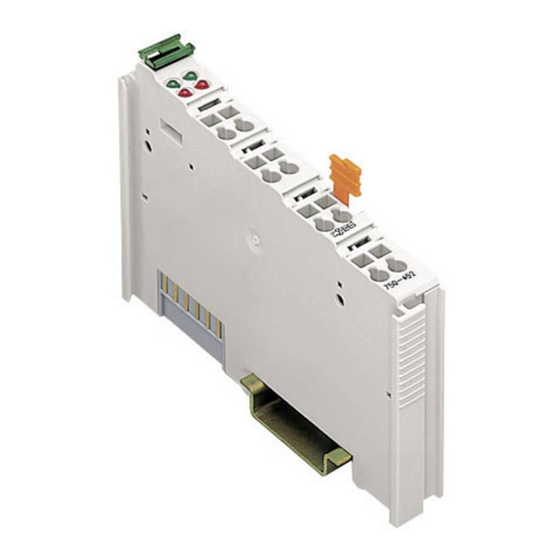
8 • 750-461, (/xxx-xxx) [2 AI Pt100/ RTD] View 2.1.2 750-461, (/xxx-xxx) [2 AI Pt100/ RTD] 2-Channel Analog Input Module for RTDs 2- or 3-wire connection 2.1.2.1 View 13 14 Function AI 2 Function AI 1 Error AI 1 Error AI 2... -
Page 9: Description
The operating mode of the 750-461/003-000 variation can be set by using the WAGO-I/O-CHECK 2 start-up and diagnostic tool (Item No.: 759-302). The default setting is Pt 100. After setting the parameters, the module behaves like the version with the selected operating mode. -
Page 10: Display Elements
This module has no power contacts. For field supply to downstream I/O modules, a supply module will be needed. The analog input module 750-461 and its variations can be used with all couplers/controllers of the WAGO-I/O-SYSTEM 750 (except for the economy types 750-320, -323, -324 and -327). -
Page 11: Schematic Diagram
750-461, (/xxx-xxx) [2 AI Pt100/ RTD] • 11 Schematic Diagram 2.1.2.5 Schematic Diagram 270pF Logic 270pF Error Function 10nF Shield Shield (screen) (screen) 750-461 Fig. 2.1.2-3: 2-Channel Analog Input Module 750-461 g046101e WAGO-I/O-SYSTEM 750 I/O Modules... -
Page 12: Technical Data
12 • 750-461, (/xxx-xxx) [2 AI Pt100/ RTD] Technical Data 2.1.2.6 Technical Data Module Specific Data Number of inputs Voltage supply via system voltage DC /DC Current consumption (internal) 80 mA max. Sensor types Pt 100 (factory preset), optionally orderable... -
Page 13: Process Image
Some fieldbus systems can process input channel status information by means of a status byte. This status byte can be displayed via the WAGO-I/O-CHECK 2 start-up and diagnostic tool. However, processing via the coupler / controller is optional, which means that accessing or parsing the status information depends on the fieldbus system. -
Page 14: I/O Modules For Pt Resistance Sensors
Thus, 0 °C corresponds to the numeric value 0x0000 and 100 °C to 0x03E8 (dec. 1000). Temperature values below 0 °C are represented in two’s complement binary form. The measured values of the resistance are directly sent by the 750-461/000- 200 (Pt 100) module. WAGO-I/O-SYSTEM 750 I/O Modules... - Page 15 750-461, (/xxx-xxx) [2 AI Pt100/ RTD] • 15 Process Image 2.1.2.7.1.1 Pt 100 The analog input modules 750-461 and 750-461/000-006 transmit 16-bit measured values per channel as well as 8 optional status bits to the coupler/controller. However, accessing the status byte depends on the fieldbus system being used.
-
Page 16: Pt 100 With Status Information For S5-Fb250 In Data Word
Process Image 2.1.2.7.1.3 Pt 100 with Status Information for S5-FB250 in Data Word The analog input module 750-461/000-200 transmits 16-bit measured values per channel as well as 8 optional status bits to the coupler/controller. When a S5 is used as higher-level control system, this data can be directly processed using the FB 250 function block. -
Page 17: I/O Modules For Ni Resistance Sensors
-60 °C to +250 °C. 2.1.2.7.2.1 Ni 100 In the Ni 100 setting 750-461/000-004, the temperature values of the sensors are represented with a resolution of 1 digit per 0.1 °C within a word (16 bits). Thus, 0 °C corresponds to the numeric value 0x0000 and 100 °C to 0x03E8 (dec. - Page 18 Process Image 2.1.2.7.2.2 Ni 1000 In the Ni 1000 setting 750-461/000-005, the temperature values of the sensors are represented with a resolution of 1 digit per 0.1 °C within a word (16 bits). Thus, 0 °C corresponds to the numeric value 0x0000 and 100 °C to 0x03E8 (dec.
-
Page 19: I/O Modules For Resistance Measuring
Measuring range: 10 Ω ... 5.0 kΩ The measured values are sent out directly when measuring the resistance. Using the 750-461/000-002 module with measuring range from 10 Ω to 1.2 kΩ, the resolution is 1 digit per 0.1 Ω. Using the 750-461/000-007 module with measuring range from 10 Ω to 5.0 kΩ, the resolution is 1 digit per 0.5 Ω. -
Page 20: Adjustable 750-461/003-000 Variation
750-461, (/xxx-xxx) [2 AI Pt100/ RTD] Adjustable 750-461/003-000 Variation 2.1.2.8 Adjustable 750-461/003-000 Variation The operating mode of the 750-461/003-000 variation can be parameterized using the WAGO-I/O-CHECK 2 start-up and diagnostic tool (Item No.: 759- 302). The default setting is Pt 100. In this operating mode, the module has the same behavior and process values as the 750-461 basic module. - Page 21 750-461, (/xxx-xxx) [2 AI Pt100/ RTD] • 21 Adjustable 750-461/003-000 Variation In WAGO-I/O-CHECK 2, the following input boxes allow you to set the offset and gain values of the user and manufacturer scaling. Input box Offset Gain User Scaling 0x0000...
-
Page 22: 750-461/020-000 [2 Ai Ntc 20Kohm]
Funktion AI 2 Fehler AI 1 Fehler AI 2 +R1 +R2 Datenkontakte 2-Leiter +R 1 +R 2 RL1 RL2 -R1 -R2 -R 1 -R 2 Schirm Schirm 750-461 /020-000 Fig. 2.1.3-1: 2-2-Channel Analog Input Module 750-461/020-000 g046103e WAGO-I/O-SYSTEM 750 I/O Modules... -
Page 23: Description
750-461/020-000 [2 AI NTC 20kOhm] • 23 Description 2.1.3.2 Description The analog input module 750-461/020-000 evaluates NTC 20kOhm resistance Temperature Devices, RTDs. The resistance value is converted to a temperature. A microprocessor within the module is used for converting and linearizing the measured resistance value into a numeric value proportional to the temperature of the selected resistance sensor. -
Page 24: Display Elements
Operational readiness and trouble-free internal data bus communication Normal operation Overrange/underflow of the admissible measuring range, broken wire 2.1.3.4 Schematic Diagram Logic 270pF Error Function 10nF Shield Shield (screen) (screen) 750-461 /020-000 Fig. 2.1.3-3: 2-Channel Analog Input Module 750-461/020-000 g046104e WAGO-I/O-SYSTEM 750 I/O Modules... -
Page 25: Technical Data
(UL508) Conformity Marking More Information Detailed references to the approvals are listed in the document "Overview Approvals WAGO-I/O-SYSTEM 750", which You can find on the CD ROM ELECTRONICC Tools and Docs (Item-No.: 0888-0412-0001-0101) or in the Internet under: www.wago.com -> Service /Downloads /Documentation /WAGO-I/O-SYSTEM 750/System Description/. -
Page 26: Process Image
Some fieldbus systems can process input channel status information by means of a status byte. This status byte can be displayed via the WAGO-I/O-CHECK 2 start-up and diagnostic tool. However, processing via the coupler / controller is optional, which means that accessing or parsing the status information depends on the fieldbus system. - Page 27 750-461/020-000 [2 AI NTC 20kOhm] • 27 Process Image WAGO-I/O-SYSTEM 750 I/O Modules...
- Page 28 WAGO Kontakttechnik GmbH & Co. KG Postfach 2880 • D-32385 Minden Hansastraße 27 • D-32423 Minden Phone: 05 71/8 87 – 0 Fax: 05 71/8 87 – 1 69 E-Mail: info@wago.com Internet: http://www.wago.com...
Need help?
Do you have a question about the 750-461 and is the answer not in the manual?
Questions and answers