
Related Manuals for WAGO 750 Series


Summary of Contents for WAGO 750 Series
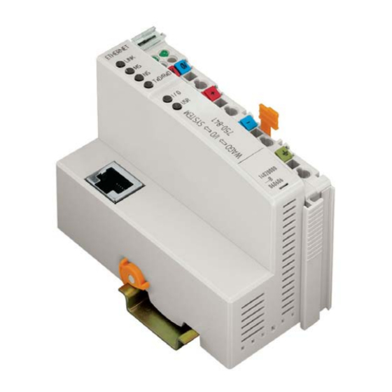
- Page 1 Fieldbus Independent I/O Modules 2 AI DC ±10 V, Differential Measurement Input 750-479 Manual Version 1.0.4...
- Page 2 • General Copyright 2007 by WAGO Kontakttechnik GmbH & Co. KG All rights reserved. WAGO Kontakttechnik GmbH & Co. KG Hansastraße 27 D-32423 Minden Phone: +49 (0) 571/8 87 – 0 Fax: +49 (0) 571/8 87 – 1 69 E-Mail: info@wago.com...
-
Page 3: Table Of Contents
750-479/000-001 [2 AI DC ±10 V Differential Measurement Input/Sync] ..................13 2.1.2.1 View....................13 2.1.2.2 Description..................13 2.1.2.3 Display Elements ................14 2.1.2.4 Schematic Diagram............... 15 2.1.2.5 Technical Data ................16 2.1.2.6 Process Image ................18 WAGO-I/O-SYSTEM 750 I/O Modules... -
Page 4: Important Comments
WAGO Kontakttechnik GmbH & Co. KG declines all liability resulting from improper action and damage to WAGO products and third party products due to non-observance of the information contained in this manual. -
Page 5: Symbols
Routines or advice for efficient use of the device and software optimization. More information References on additional literature, manuals, data sheets and INTERNET pages 1.3 Number Notation Number Code Example Note Decimal normal notation Hexadecimal 0x64 C notation Binary '100' Within ', '0110.0100' Nibble separated with dots WAGO-I/O-SYSTEM 750 I/O Modules... -
Page 6: Safety Notes
1.5 Scope This manual describes the Analog Input Module 750-479 2 AI DC ±10 V, Differential Measurement Input of the modular WAGO-I/O- SYSTEM 750. Handling, assembly and start-up are described in the manual of the Fieldbus Coupler. -
Page 7: O Modules
LED. Any configuration of the input modules is possible when designing the fieldbus node. Grouping of module types is not necessary. The voltage supply is done via system voltage. WAGO-I/O-SYSTEM 750 I/O Modules... -
Page 8: Display Elements
This module has no power contacts. For field supply to downstream I/O modules, a supply module will be needed. The analog input module 750-479 can be used with all couplers/controllers of the WAGO-I/O-SYSTEM 750 (except for the economy types 750-320, -323, -324 and -327). 2.1.1.3... -
Page 9: Schematic Diagram
750-479 [2 AI DC ±10 V, Differential Measurement Input] • 9 Schematic Diagram 2.1.1.4 Schematic Diagram +AI 2 +AI 1 Logic -AI 1 -AI 2 270pF 270pF Error Function Shield Shield (screen) (screen) 750-479 Fig. 2.1.1-3: Schematic diagram g0479001e WAGO-I/O-SYSTEM 750 I/O Modules... -
Page 10: Technical Data
* from upper edge of 35 DIN rail Weight ca. 55 g Standards and Regulations (cf. Chapter 2.2 of the Coupler/Controller Manual) EMC-Immunity to interference (CE) acc. to EN 50082-2 (96) EMC-Emission of interference (CE) acc. to EN 50081-1 (93) WAGO-I/O-SYSTEM 750 I/O Modules... -
Page 11: Process Image
II 3 GD EEx nA II T4 Conformity Marking More Information Detailed references to the approvals are listed in the document "Overview Approvals WAGO-I/O-SYSTEM 750", which you can find on the CD ROM ELECTRONICC Tools and Docs (Item-No.: 0888-0412) or in the internet under: www.wago.com... - Page 12 Some fieldbus systems can process input channel status information by means of a status byte. This status byte can be displayed via the starting tool WAGO-I/O-CHECK 2. However, processing via the coupler / controller is optional, which means that accessing or parsing the status information depends on the fieldbus system.
-
Page 13: 750-479/000-001 [2 Ai Dc ±10 V Differential Measurement Input/Sync]
The Shield (sreen) is directly connected to the DIN rail. A capacitive connection is made automatically when snapped onto the DIN rail. The input signal of each channel is electrically isolated and will be transmitted with a resolution of 14 bits(13 bits + sign bit). WAGO-I/O-SYSTEM 750 I/O Modules... -
Page 14: Display Elements
This module has no power contacts. For field supply to downstream I/O modules, a supply module will be needed. The analog input module 750-479/000-001 can be used with all couplers/controllers of the WAGO-I/O-SYSTEM 750 (except for the economy types 750-320, -323, -324 and -327). 2.1.2.3... -
Page 15: Schematic Diagram
750-479/000-001 [2 AI DC ±10 V Differential Measurement Input/Sync] • 15 Schematic Diagram 2.1.2.4 Schematic Diagram +AI 2 +AI 1 Logic -AI 1 -AI 2 270pF 270pF Error Function Shield Shield (screen) (screen) 750-479 Fig. 2.1.2-3: Schematic diagram g0479001e WAGO-I/O-SYSTEM 750 I/O Modules... -
Page 16: Technical Data
2 x 16 bits data 2 x 8 bits control/status (option) Dimensions W x H* x L 12 mm x 64 mm x 100 mm * from upper edge of 35 DIN rail Weight ca. 55 g WAGO-I/O-SYSTEM 750 I/O Modules... - Page 17 (as from version 0101)) More Information Detailed references to the approvals are listed in the document "Overview Approvals WAGO-I/O-SYSTEM 750", which you can find on the CD ROM ELECTRONICC Tools and Docs (Item-No.: 0888-0412) or in the internet under: www.wago.com...
-
Page 18: Process Image
'1110.0000.0000.00 00' 0xE000 -8192 0x00 -5.0 '1100.0000.0000.00 00' 0xC000 -16384 0x00 -7.5 '1010.0000.0000.00 00' 0xA000 -24576 0x00 -10.0 '1000.0000.0000.00 00' 0x8000 -32768 0x00 <-10.0 '1000.0000.0000.00 01' 0x8001 -32767 0x41 status informations: F: Error, Ü: over control WAGO-I/O-SYSTEM 750 I/O Modules... - Page 19 750-479/000-001 [2 AI DC ±10 V Differential Measurement Input/Sync] • 19 Process Image WAGO-I/O-SYSTEM 750 I/O Modules...
- Page 20 WAGO Kontakttechnik GmbH & Co. KG Postfach 2880 • D-32385 Minden Hansastraße 27 • D-32423 Minden Phone: 05 71/8 87 – 0 Fax: 05 71/8 87 – 1 69 E-Mail: info@wago.com Internet: http://www.wago.com...
Need help?
Do you have a question about the 750 Series and is the answer not in the manual?
Questions and answers