
Related Manuals for WAGO I/O SYSTEM 750 750-833


Summary of Contents for WAGO I/O SYSTEM 750 750-833
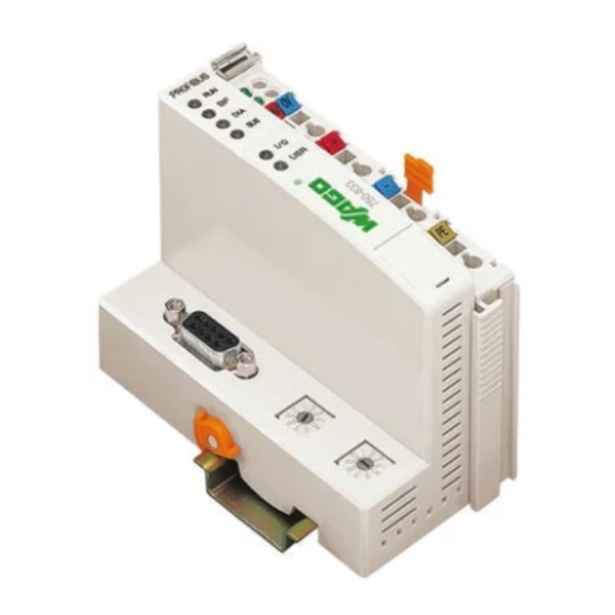
- Page 1 Modular I/O-System PROFIBUS DP/V1 Programmable Field Bus Controller 750-833 Manual Technical description, installation and configuration Version 1.0.0...
- Page 2 • General Copyright © 2008 by WAGO Kontakttechnik GmbH & Co. KG. All rights reserved. WAGO Kontakttechnik GmbH & Co. KG Hansastraße 27 D-32423 Minden Phone: +49 (0) 571/8 87 – 0 Fax: +49 (0) 571/8 87 – 1 69 E-Mail: info@wago.com...
-
Page 3: Table Of Contents
Safety Information.................. 13 Font Conventions ................... 14 Number Notation..................14 Scope ...................... 15 Abbreviation................... 15 2 The WAGO-I/O-SYSTEM 750 ..............16 System Description................. 16 Technical Data..................17 Manufacturing Number ................23 Component Update................. 24 Storage, Assembly and Transport ............24 Mechanical Setup ................... - Page 4 3.4.6.3 Flags ....................68 3.4.6.4 Calculate Addresses ..............68 3.4.6.5 Example for Absolute Addresses..........69 Programming of the PFC with WAGO-I/O-PRO ........70 3.5.1 PROFIBUS Library for WAGO-I/O-PRO ........70 3.5.2 IEC 61131-3 Program Transfer ............71 3.5.2.1 Transmission via the Serial Interface..........71 3.5.2.2...
- Page 5 Digital Output Modules ..............128 5.1.3 Analog Input Modules ..............129 5.1.4 Analog Output Modules ..............131 5.1.5 Special Modules ................132 5.1.6 System Modules ................134 Design of the Process Data for PROFIBUS-DP ........135 WAGO-I/O-SYSTEM 750 Bus System...
- Page 6 2 DO I/O Modules ..............168 5.4.1.7 2 (1) DO I/O Modules with 1 Bit Diagnostics per Channel ..169 5.4.1.8 2 DO I/O Module with 2 Bit Diagnostics per Channel....171 5.4.1.9 4 DO I/O Modules ..............173 WAGO-I/O-SYSTEM 750 Bus System...
- Page 7 5.5.18 4 AO I/O Modules ................218 5.5.19 Counter Module 750-404..............220 5.5.20 Counter Module 750-638 and PWM Module 750-511 ....221 5.5.21 SSI Interface ..................222 5.5.22 Incremental Encoder Interfaces and Serial Interfaces ..... 222 5.5.23 Digital Impulse Interface ..............223 WAGO-I/O-SYSTEM 750 Bus System...
- Page 8 Divisions ..................232 6.4.2 Explosion Protection Groups............232 6.4.3 Temperature Classes................ 233 Identification ..................234 6.5.1 For Europe ..................234 6.5.2 For America ..................235 Installation Regulations................ 236 7 List of Literature ..................238 8 Index ......................239 WAGO-I/O-SYSTEM 750 Bus System...
-
Page 9: Important Notes
WAGO Kontakttechnik GmbH & Co. KG, Minden. Non-observance will entail the right of claims for damages. WAGO Kontakttechnik GmbH & Co. KG reserves the right of changes serving technical progress. All rights developing from the issue of a patent or the legal protection of utility patents are reserved to WAGO Kontakttechnik GmbH &... -
Page 10: Conforming Use Of Series 750
All personnel must be familiar with the applicable standards. WAGO Kontakttechnik GmbH & Co. KG declines any liability resulting from improper action and damage to WAGO products and third party products due to non-observance of the information contained in this manual. -
Page 11: Standards And Regulations For Operating The 750 Series
(emissions of interference) according to EN 61000-6-3. You will find the relevant information in the section on "WAGO-I/O-SYSTEM 750" ! "System Description" ! "Technical Data". • Please observe the safety measures against electrostatic discharge according to DIN EN 61340-5-1/-3. -
Page 12: Symbols
Observe the precautionary measure for handling components at risk of electrostatic discharge. Note Make important notes that are to be complied with so that a trouble-free and efficient device operation can be guaranteed. Additional Information References to additional literature, manuals, data sheets and internet pages. WAGO-I/O-SYSTEM 750 Bus System... -
Page 13: Safety Information
Danger The WAGO-I/O-SYSTEM 750 and its components are an open system. It must only be assembled in housings, cabinets or in electrical operation rooms. Access is only permitted via a key or tool to authorized qualified personnel. -
Page 14: Font Conventions
Important Notes Font Conventions 1.5 Font Conventions Names of paths and files are marked in italic. italic e.g.: C:\Programs\WAGO-IO-CHECK Menu items are marked in bold italic. italic e.g.: Save A backslash between two names characterizes the selection of a menu point from a menu. -
Page 15: Scope
Important Notes • 15 Scope 1.7 Scope This manual describes all components of the field bus independent WAGO I/O SYSTEM 750 with programmable field bus controller. Item No. Description 750-833 Programmable Field Bus Controller PROFIBUS DP/V1 12 MBd 1.8 Abbreviation... -
Page 16: The Wago-I/O-System 750
The WAGO-I/O-SYSTEM 750 has a clear port level with LEDs for status indication, insertable mini WSB markers and pullout group marker carriers. The 3-wire technology supplemented by a ground wire connection allows for direct sensor/actuator wiring. -
Page 17: Technical Data
The WAGO-I/O-SYSTEM 750 • 17 Technical Data 2.2 Technical Data Mechanic Material Polycarbonate, Polyamide 6.6 Dimensions W x H* x L * from upper edge of DIN 35 rail - Coupler/Controller (Standard) - 51 mm x 65 mm x 100 mm... - Page 18 18 • The WAGO-I/O-SYSTEM 750 Technical Data Safe electrical isolation Air and creepage distance acc. to IEC 60664-1 Degree of pollution acc. To IEC 61131-2 Degree of protection Degree of protection IP 20 Electromagnetic compatibility Immunity to interference for industrial areas acc. to EN 61000-6-2 (2001)
- Page 19 The WAGO-I/O-SYSTEM 750 • 19 Technical Data Mechanical strength acc. to IEC 61131-2 Test specification Frequency range Limit value 5 Hz ≤ f < 9 Hz IEC 60068-2-6 vibration 1.75 mm amplitude (permanent) 3.5 mm amplitude (short term) 9 Hz ≤ f < 150 Hz 0.5 g (permanent)
- Page 20 20 • The WAGO-I/O-SYSTEM 750 Technical Data For Products of the WAGO-I/O-SYSTEM 750 with ship specific approvals supplementary guidelines are valid: Electromagnetic compatibility Immunity to interference acc. to Germanischer Lloyd (2003) Test specification Test values Strength Evaluation class criteria IEC 61000-4-2 ESD...
- Page 21 In Germany, the Federal Office for Post and Telecommunications and its branch offices issues the permit. It is possible to use other field bus couplers/controllers under certain boundary conditions. Please contact WAGO Kontakttechnik GmbH & Co. KG. Maximum power dissipation of the components Bus modules 0.8 W / bus terminal (total power dissipation,...
- Page 22 22 • The WAGO-I/O-SYSTEM 750 Technical Data Dimensions 01 02 24V 0V Side view Dimensions in mm Fig. 2-2: Dimensions g01xx05e Note The illustration shows a standard coupler. For detailed dimensions, please refer to the technical data of the respective coupler/controller.
-
Page 23: Manufacturing Number
The manufacturing number consists of the production week and year, the software version (if available), the hardware version of the component, the firmware loader (if available) and further internal information for WAGO Kontakttechnik GmbH & Co. KG. WAGO-I/O-SYSTEM 750 Bus System... -
Page 24: Component Update
24 • The WAGO-I/O-SYSTEM 750 Component Update 2.4 Component Update For the case of an Update of one component, the lateral marking on each component contains a prepared matrix . This matrix makes columns available for altogether three updates to the entry of the current update data, like production order number (NO;... -
Page 25: Mechanical Setup
The WAGO-I/O-SYSTEM 750 • 25 Mechanical Setup 2.6 Mechanical Setup 2.6.1 Installation Position Along with horizontal and vertical installation, all other installation positions are allowed. Attention In the case of vertical assembly, an end stop has to be mounted as an additional safeguard against slipping. -
Page 26: Assembly Onto Carrier Rail
WAGO Kontakttechnik GmbH & Co. KG supplies standardized carrier rails that are optimal for use with the I/O system. If other carrier rails are used, then a technical inspection and approval of the rail by WAGO Kontakttechnik GmbH & Co. KG should take place. -
Page 27: Wago Din Rail
The WAGO-I/O-SYSTEM 750 • 27 Mechanical Setup 2.6.3.2 WAGO DIN Rail WAGO carrier rails meet the electrical and mechanical requirements. Item Number Description 210-113 /-112 35 x 7.5; 1 mm; steel yellow chromated; slotted/unslotted 210-114 /-197 35 x 15; 1.5 mm; steel yellow chromated; slotted/unslotted 210-118 35 x 15;... -
Page 28: Plugging And Removal Of The Components
28 • The WAGO-I/O-SYSTEM 750 Mechanical Setup 2.6.5 Plugging and Removal of the Components Warning Before work is done on the components, the voltage supply must be turned off. In order to safeguard the coupler/controller from jamming, it should be fixed onto the carrier rail with the locking disc To do so, push on the upper groove of the locking disc using a screwdriver. -
Page 29: Assembly Sequence
The WAGO-I/O-SYSTEM 750 • 29 Mechanical Setup 2.6.6 Assembly Sequence All system components can be snapped directly on a carrier rail in accordance with the European standard EN 50022 (DIN 35). The reliable positioning and connection is made using a tongue and groove system. -
Page 30: Internal Bus/Data Contacts
30 • The WAGO-I/O-SYSTEM 750 Mechanical Setup 2.6.7 Internal Bus/Data Contacts Communication between the coupler/controller and the bus modules as well as the system supply of the bus modules is carried out via the internal bus. It is comprised of 6 data contacts, which are available as self-cleaning gold spring contacts. -
Page 31: Power Contacts
Fig. 2-8: Example for the arrangement of power contacts g0xxx05e Recommendation With the WAGO ProServe® Software smartDESIGNER, the structure of a field bus node can be configured. The configuration can be tested via the integrated accuracy check. WAGO-I/O-SYSTEM 750... -
Page 32: Wire Connection
More than one conductor per connection is not permissible. If several conductors have to be made at one connection point, then they should be made away from the connection point using WAGO Terminal Blocks. The terminal blocks may be jumpered together and a single wire brought back to the I/O module connection point. -
Page 33: Power Supply
The WAGO-I/O-SYSTEM 750 • 33 Power Supply 2.7 Power Supply 2.7.1 Isolation Within the field bus node, there are three electrically isolated potentials. • Operational voltage for the field bus interface. • Electronics of the couplers/controllers and the bus modules (internal bus). -
Page 34: System Supply
2.7.2 System Supply 2.7.2.1 Connection The WAGO-I/O-SYSTEM 750 requires a 24 V direct current system supply (-15 % or +20 %). The power supply is provided via the coupler/controller and, if necessary, in addition via the internal system supply modules (750-613). -
Page 35: Alignment
The WAGO-I/O-SYSTEM 750 • 35 Power Supply Attention Resetting the system by switching on and off the system supply, must take place simultaneously for all supply modules (coupler/controller and 750-613). 2.7.2.2 Alignment Recommendation A stable network supply cannot be taken for granted always and everywhere. - Page 36 (750-613), e.g. in the middle of the node, should be added. Recommendation With the WAGO ProServe® Software smartDESIGNER, the assembly of a field bus node can be configured. The configuration can be tested via the integrated accuracy check.
-
Page 37: Field Supply
The WAGO-I/O-SYSTEM 750 • 37 Power Supply 2.7.3 Field Supply 2.7.3.1 Connection Sensors and actuators can be directly connected to the relevant channel of the bus module in 1/4 conductor connection technology. The bus module supplies power to the sensors and actuators. The input and output drivers of some bus modules require the field side supply voltage. -
Page 38: Fusing
38 • The WAGO-I/O-SYSTEM 750 Power Supply Attention Some bus modules have no or very few power contacts (depending on the I/O function). Due to this, the passing through of the relevant potential is disrupted. If a field supply is required for subsequent bus modules, then a power supply module must be used. - Page 39 The WAGO-I/O-SYSTEM 750 • 39 Power Supply Warning In the case of power supply modules with fuse holders, only fuses with a maximum dissipation of 1.6 W (IEC 127) must be used. For UL approved systems only use UL approved fuses.
- Page 40 40 • The WAGO-I/O-SYSTEM 750 Power Supply Alternatively, fusing can be done externally. The fuse modules of the WAGO series 281 and 282 are suitable for this purpose. Fig. 2-18: Fuse modules for automotive fuses, series 282 pf66800x Fig. 2-19: Fuse modules with pivotable fuse carrier, series 281 pe61100x Fig.
-
Page 41: Supplementary Power Supply Regulations
Power Supply 2.7.4 Supplementary Power Supply Regulations The WAGO-I/O-SYSTEM 750 can also be used in shipbuilding or offshore and onshore areas of work (e. g. working platforms, loading plants). This is demonstrated by complying with the standards of influential classification companies such as Germanischer Lloyd and Lloyds Register. -
Page 42: Supply Example
42 • The WAGO-I/O-SYSTEM 750 Power Supply 2.7.5 Supply Example Attention The system supply and the field supply should be separated in order to ensure bus operation in the event of a short-circuit on the actuator side. 750-400 750-410 750-401... -
Page 43: Power Supply Unit
• 43 Power Supply 2.7.6 Power Supply Unit The WAGO-I/O-SYSTEM 750 requires a 24 V direct current system supply with a maximum deviation of -15 % or +20 %. Recommendation A stable network supply cannot be taken for granted always and everywhere. -
Page 44: Grounding
The optimal insulated setup is a metallic assembly plate with grounding connection with an electrical conductive link with the carrier rail. The separate grounding of the carrier rail can be easily set up with the aid of the WAGO ground wire terminals. Item No. Description... -
Page 45: Grounding Function
The WAGO-I/O-SYSTEM 750 • 45 Grounding 2.8.2 Grounding Function The grounding function increases the resistance against disturbances from electro-magnetic interferences. Some components in the I/O system have a carrier rail contact that dissipates electro-magnetic disturbances to the carrier rail. Fig. 2-23: Carrier rail contact... -
Page 46: Grounding Protection
46 • The WAGO-I/O-SYSTEM 750 Grounding 2.8.3 Grounding Protection For the field side, the ground wire is connected to the lowest connection terminals of the power supply module. The ground connection is then connected to the next module via the Power Jumper Contact (PJC). If the bus... -
Page 47: Shielding (Screening)
Note For a better shield performance, the shield should have previously been placed over a large area. The WAGO shield connection system is suggested for such an application. This suggestion is especially applicable if the equipment can have even current or high impulse formed currents running through (for example initiated by atmospheric discharge). -
Page 48: Wago Shield (Screen) Connecting System
Assembly Guidelines/Standards 2.9.4 WAGO Shield (Screen) Connecting System The WAGO Shield Connecting system includes a shield clamping saddle, a collection of rails and a variety of mounting feet. Together these allow many different possibilities. See catalog W4 volume 3 chapter 10. -
Page 49: Programmable Field Bus Controller 750-833
The physical structure of the field bus node may be individually adapted to the configuration of each system without changing the addressing of a global control application. This is done by parameterizing the modules accordingly with the aid of the planning environment (for instance, WAGO NETCON, COM PROFIBUS, STEP7, Profi-Map, etc.). WAGO-I/O-SYSTEM 750... - Page 50 • Automatic recognition of the transmission speed on the PROFIBUS of 9.6 kBd to 12 MBd • All I/O modules from the WAGO-I/O-SYSTEM 750 are supported • Configuration modules can be parameterized as wildcards. • Parameterizable substitute value for each channel •...
-
Page 51: Hardware
• Configuration and programming interface • Operating mode switch • Electronics for communication with the I/O modules (internal bus) and the field bus interface WAGO-I/O-SYSTEM 750 Bus System... -
Page 52: Device Supply
The integrated internal system supply module generates the necessary voltage to supply the electronics and the connected I/O modules. The field bus interface is supplied with galvanically isolated voltage from the internal system supply module. WAGO-I/O-SYSTEM 750 Bus System... -
Page 53: Field Bus Connection
The galvanic isolation between the field bus system and the electronics is achieved by means of DC/DC converter and optocoupler. The connection point is mechanically lowered permitting fitting in an 80 mm high switch box once connected. WAGO-I/O-SYSTEM 750 Bus System... -
Page 54: Display Elements
The USR-LED can be selected by a user program in a / orange programmable field bus controller. green Status of the operating voltage – system green Status of the operating voltage – power jumper contacts LED-Position depends on manufacturer WAGO-I/O-SYSTEM 750 Bus System... -
Page 55: Station Address
PFC functions, without the field bus being active. Using this function, an Stand Alone, smallest scale control can be realized using the WAGO-I/O-SYSTEM 750 Any station address may be used from SW 03. The user determines whether the controller may start up with the default configuration using a functional building block. -
Page 56: Configuration And Programming Interface
Programmable Field Bus Controller 750-833 Hardware 3.2.6 Configuration and Programming Interface The configuration and programming interface is located behind the cover flap. This is used to communicate with WAGO-I/O-CHECK and WAGO-I/O-PRO as well as for firmware transmitting. Fig. 3.2.6-6: Configuration interface g01xx07e The communication cable (750-920) is connected to the 4 pole male header. -
Page 57: Operating Mode Switch
Note With "GET_STOP_VALUE" (library "System.lib") WAGO-I/O-PRO provides a function which serves to recognize the last cycle prior to a program stop giving the user the possibility to program the behavior of the controller in case of a STOP. -
Page 58: Operating System
. The I/O-LED lights up green. A PFC user program does not yet exist in the flash memory when delivered. The controller runs-up as described, without initializing the system. It then behaves as a coupler. WAGO-I/O-SYSTEM 750 Bus System... -
Page 59: Pfc Cycle
The PFC cycle starts following a fault free run-up when the operating mode switch is in the top position or by a start command from the WAGO-I/O- PRO. The input and output data of the field bus and the I/O modules as well as the times are read. - Page 60 Fieldbus data, Writing outputs data of I/O modules Operating system functions, updating times operating mode switch STOP is in the top position or Operating mode start command in WAGO-IO- Online/Start Online/Stop Fig. 3.3.2-8: Operating system 750-833 g012112e WAGO-I/O-SYSTEM 750 Bus System...
-
Page 61: Process Image
The process is mapped on the PROFIBUS with the module configuration. This is the reason why this description is only important for programming the controller with WAGO-I/O-PRO. After power-up, the controller recognizes all I/O modules connected in the node (data width/bit width > 0). Analog and digital I/O modules can be mixed. -
Page 62: Allocation Of The Input And Output Data
PROFIBUS DP Telegram. Fig. 3.4.2-9: Allocation of the input and output data g012117e WAGO-I/O-SYSTEM 750 Bus System... - Page 63 IEC 61131-3 input variable = PFC output variable PFC input variable = IEC 61131-3 output variable Programmable fieldbus controller Fieldbus input input variables variables output output variables variables Fig. 3.4.2-10: Correlation of IEC 61131-3 variables and PFC variables g012444e WAGO-I/O-SYSTEM 750 Bus System...
-
Page 64: Process Data Structure For Profibus-Dp
PFC variables behind the physical process image. The division of the memory spaces and the access of the PLC functionality (CPU) to the process data is identical with all WAGO field bus controllers. Access is via an application related IEC 61131-3 program and independent on the field bus system. - Page 65 The variables processed by the CPU via the IEC 61131-3 program are filed in the output memory space and can be read out by the master. In addition, the controller offers further memory spaces, which cannot be accessed from the field bus side: WAGO-I/O-SYSTEM 750 Bus System...
- Page 66 RAM memory. After an error-free start-up, the PFC cycle starts when the operating mode switch is turned to its upper position or by a start command from WAGO-I/O-PRO. WAGO-I/O-SYSTEM 750 Bus System...
-
Page 67: Addressing
The structure of the process image is described in chapter 3.4., “Process Image” is done in this structure. Input data %IW0 word oriented data bit oriented data Output data %QW0 word oriented data bit oriented data WAGO-I/O-SYSTEM 750 Bus System... -
Page 68: Field Bus Variables
Byte Address 1st byte: 2 x Word address 2nd byte: 2 x Word address + 1 lower section: Word address (even numbers) / 2 Dword Address upper section: Word address (odd numbers) / 2, rounded off WAGO-I/O-SYSTEM 750 Bus System... -
Page 69: Example For Absolute Addresses
Data Size Flags %MX11.0 ... 15 %MX12.0 ... 15 Byte %MB22 %MB23 %MB24 %MB25 Word %MW11 %MW12 Dword %MD5 (upper part) %MD6 (lower part) The character 'X' for single bits can be deleted, e. g.%I14.0, %Q6.10, %M11.7 WAGO-I/O-SYSTEM 750 Bus System... -
Page 70: Programming Of The Pfc With Wago-I/O-Pro
WAGO-I/O-PRO. This manual, however, does not include a description of how to program with WAGO-I/O-PRO. In contrast, the following chapters are to describe the special modules for WAGO-I/O-PRO for you to utilize explicitly for programming the PROFIBUS field bus controller. -
Page 71: Iec 61131-3 Program Transfer
3.5.2.1 Transmission via the Serial Interface Use the WAGO communication cable to produce a physical connection via the serial interface. This is contained in the scope of delivery of the programming tool IEC 1131-3, order No.: 759-333, or can be purchased as an accessory under order No.: 750-920. - Page 72 Programmable Field Bus Controller 750-833 Programming of the PFC with WAGO-I/O-PRO 1. Start the WAGO-I/O-PRO software via 'Start/Programs' or by double clicking on the WAGO-I/O-PRO symbol on your desk top. 2. In the "Online" menu click on the "Communication parameters" menu point.
-
Page 73: Transmission Via The Field Bus
(byte 19) must be set to 0x81. 1. Start the WAGO-I/O-PRO software via 'Start/Programs' or by double clicking on the WAGO-I/O-PRO symbol on your desktop. 2. In the "Online" menu click on the "Communication parameters" menu point 3. Click on the "New" button to define a driver in the "Communication parameter"... -
Page 74: Msac2 Interface
PROFIBUS telegram. The transmission speed depends on the physical requirements of PROFIBUS (e.g. baud rate). 1. Start the WAGO-I/O-PRO software via 'Start/Programs' or by double clicking on the WAGO-I/O-PRO- symbol on your desktop. 2. In the "Online" menu click on the "Communication parameters" menu point 3. - Page 75 Waiting time in ms for the preparation of the station list - Data base To operate the PROFIBUS card (WAGO) as a class 2 master, the data base on the card must be deleted only once by WAGO-I/O-PRO. Once the data base has been deleted, it can be left unchanged.
-
Page 76: Configuration
„not plug fitted“. In this manner the process data still on the PROFIBUS DP can be filtered for the individual module and not transmitted to the periphery or read by it. WAGO-I/O-SYSTEM 750 Bus System... -
Page 77: Configuration Of The Field Bus Variables
The SFC 14 or SFC 15 is to be used with S7 if the PFC inputs or PFC outputs are more than 4 bytes. The same also applies for I/O modules with a data width of more than 4 bytes. WAGO-I/O-SYSTEM 750 Bus System... -
Page 78: Gsd Files
GSD and symbol files for the configuration of the I/O modules are available on the CD ROM ELECTRONICC Tools and Docs (Art.-Nr.: 0888-0412) or at http://www.wago.com. GSD File for I/O Module 750-833 WAGOB756.GSD The GSD file is read by the configuration software and the corresponding settings are transferred. -
Page 79: Identification Bytes
15 = no manufacturer specific data follows Input and output Spec. identification formats Input and output unassigned slot a length byte for inputs follows a length byte for outputs follows a length byte each for inputs and outputs follows WAGO-I/O-SYSTEM 750 Bus System... - Page 80 Structure of the length bytes: Octet 2 / 3 Meaning Data length 1 byte or word 63 bytes or 63 words Formats Byte structure Consistency about Total length WAGO-I/O-SYSTEM 750 Bus System...
- Page 81 Array Of Floating Point This information is saved in the GSD file. For projecting, the I/O module is selected in accordance with the item number using the configuration software contained in the hardware catalogue of the I/O module. WAGO-I/O-SYSTEM 750 Bus System...
-
Page 82: Bus Controller Modules
0xB1 750-833 4 byte process data channel 0xB3 3.6.4.2 I/O Modules Note You can find a list of all I/O modules with all possible identification bytes in chapter 5.3 “PROFIBUS Identification Bytes of I/O Modules “. WAGO-I/O-SYSTEM 750 Bus System... -
Page 83: Example
750-504 4 DO/24 V DC/0.5 A AB8.0 0x20 Digital output AB8.1 Digital output AB8.2 Digital output AB8.3 Digital output *750-504 4 DO/24 V DC/0.5 A AB8.4 0x00 Digital output AB8.5 Digital output AB8.6 Digital output AB8.7 WAGO-I/O-SYSTEM 750 Bus System... - Page 84 AB10.0 0x20 Digital output AB10.1 Digital output AB10.2 Digital output AB10.3 End module End module * The master addresses listed in the table correspond to the allocation of the process data given in the master configuration. WAGO-I/O-SYSTEM 750 Bus System...
-
Page 85: Parameterization Of The Controllers
PFC image Projecting of virtual PFC When projecting PFC modules using the modules PROFIBUS DP configuration tool, the modules not possible cannot be parameterized as “not being connected” possible can be parameterized as “not being connected” WAGO-I/O-SYSTEM 750 Bus System... - Page 86 Internal bus restart after fault: AUTORESET reserved Table 0, register 2 HB, reserved Table 0, register 3 LB '011' reserved Data format byte orientated I/O modules: INTEL Data format byte orientated I/O modules: MOTOROLA '1100' reserved WAGO-I/O-SYSTEM 750 Bus System...
- Page 87 - DPV1 compatible - S7 compatible '00' reserved '0000.0000' Table 100, register 1 LB, reserved '0000.0000' Table 100, register 1 HB, reserved '0000.0000' Table 100, register 2 LB, reserved '0000.0000' Table 100, register 2 HB, reserved WAGO-I/O-SYSTEM 750 Bus System...
-
Page 88: Configuration And Parameterization Of The Modules
3.8.1 Process Data Channel of the Bus Controller The process data channel , which has been parameterized as PFC interface and which requires 2-byte I/O data, is used for communication between WAGO- I/O-PRO and the run-time system of the field bus controller as described before. -
Page 89: Parameterization Of I/O Modules
3.8.2 Parameterization of I/O Modules Note You can find a list of all I/O modules with all possible parameters in chapter 5.4 “Configuration and Parameterization of the I/O Modules”. WAGO-I/O-SYSTEM 750 Bus System... -
Page 90: Diagnostics
(3 bytes per message). Byte Station status 1 Station status 2 Station status 3 DP-Master-Address Manufacturer identification Diagnostics module based (8 byte) Device status Diagnostics channel based Status (3 byte per channel) parameterization (5 byte per module) WAGO-I/O-SYSTEM 750 Bus System... -
Page 91: Stations Status 1 To 3
31 30 29 28 27 26 25 24 39 38 37 36 35 34 33 32 47 46 45 44 43 42 41 40 55 54 53 52 51 50 49 48 63 62 61 60 59 58 57 56 WAGO-I/O-SYSTEM 750 Bus System... -
Page 92: Device Status
(manufacturer specific device status) Slot number 0 Status differentiation (none) Status message q – Status source '00' Internal status '01' Internal bus status '10' PROFIBUS DP status '11' PFC-RTS status n – Status number Status argument Reserved WAGO-I/O-SYSTEM 750 Bus System... -
Page 93: Internal Status Messages And Arguments
At least one module cannot interpret an internal bus command 0x44 0x00 A data fault or a internal bus interruption exists behind the controller 0x44 An internal bus interruption exists behind module n 0x45 Fault during register communication with module n WAGO-I/O-SYSTEM 750 Bus System... -
Page 94: Profibus Dp Status Messages And Arguments
Compilate buffer overflow for DP process image 0x86 0x02 Compilate buffer overflow for PFC process image 3.9.5.4 PFC-RTS Status Messages and Arguments Status Status Description Message Argument 0xC1 0x00 t. b. d. 0xC1 0x01 t. b. d. 0xC2 0x00 t. b. d. WAGO-I/O-SYSTEM 750 Bus System... -
Page 95: Channel Based Diagnostics
Header diagnostics channel based Type of 23 + n Signal channel signal Signal channel 1 ... 8 0 Signal channel 1 1 Signal channel 2 7 Signal channel 8 Type of signal Input Output Input / Output WAGO-I/O-SYSTEM 750 Bus System... - Page 96 0 1 0 2 bit 0 1 1 4 bit 1 0 0 1 byte 1 0 1 1 word 1 1 0 2 words n : Offset of the diagnostics message in the diagnostics buffer WAGO-I/O-SYSTEM 750 Bus System...
-
Page 97: Fault Types Of I/O Modules With Diagnostics Capability
Programmable Field Bus Controller 750-833 • 97 Diagnostics 3.9.6.1 Fault Types of I/O Modules with Diagnostics Capability The fault numbers 0 to 9 refer to standardized fault descriptions. The WAGO specific faults are arranged from fault number 17. Fault Meaning Type... -
Page 98: I/O Modules Fault Cases
'110 0.0111' Upper limit value exceeded 0.1000' Lower limit value gone below 750-641 '000 0.1001' Fault 1.1011' Frame fault 1.1101' Bus error 750-642, 750-650, '110 1.0011' Receiver buffer overflow 750-651, 750-653 ('000) 1.1111' I/O module fault WAGO-I/O-SYSTEM 750 Bus System... - Page 99 Bus error (AS interface flags offer more information) 750-660, 750-665, '001 1.1000' The register of the I/O module, which is 750-666 ('000) referenced by the type of signal and the signal channel, contains a diagnostics message. 1.1111' Terminal fault WAGO-I/O-SYSTEM 750 Bus System...
-
Page 100: Parameterization Status Profisafe
The CRC, which was determined by the F module via the PROFIsafe (0x47) parameters (CRC1), varies from the CRC1 transmitted in the parameterization telegram. (0x48) Reserved fault numbers, which are not allowed to be used or evaluated. (0x49) WAGO-I/O-SYSTEM 750 Bus System... -
Page 101: Acyclic Communication According To Dp/V1
(MSAC1) and master class 2/ slave functions (MSAC2). Both initiating and aborting the communication channel is required so that the MSAC2 connection can be monitored. Monitoring a MSAC1 connection is done via the MSCY0 connection, which is always required. WAGO-I/O-SYSTEM 750 Bus System... - Page 102 Once the connection has been established, it will be monitored by the C2 master. When failures occur, both the master and the slave can close the connection via MSAC2_Abort. The bus coupler is able to manage a MSAC2 connection. WAGO-I/O-SYSTEM 750 Bus System...
-
Page 103: Data Areas
In this case, however, the data to be written will not be transferred to the complex I/O module. The transfer only occurs if the write protection is reset. WAGO-I/O-SYSTEM 750 Bus System... -
Page 104: Field Bus Coupler, Slots 0 And 1
Physical module arrangement MSAC1/2_Read / 2 … 65 ... 99 Reserved for expansions MSAC1/2_Write / 1 ... 138 Reserved for WAGO-IO-PRO MSAC1/2_Read / 1 ... 138 Reserved for expansions Field bus input image MSAC1/2_Read / 1 ... 240 Field bus input image MSAC1/2_Read / 1 ... -
Page 105: Complex I/O Modules, Slots 1
Accessing the data areas of the third channel while using a 2-channel module. Requesting the input data of an output module. Requesting the output data of an input module. Requesting the diagnostics data of a module that has no diagnostics information. WAGO-I/O-SYSTEM 750 Bus System... - Page 106 Service Error_Frame Octet 2 Error_Decode Octet 3 Error_Code_1 Error_Class Octet 4 Error_Code_2 User specific Abb. 3.10.2-13: Coding of error messages g012121e Octet 2 Error Decode Meaning 0 ... 127 Reserved PROFIBUS-DP/V1 129 ... 254 Reserved PROFIBUS-FMS WAGO-I/O-SYSTEM 750 Bus System...
- Page 107 Access denied Invalid scaling Invalid parameter Invalid type 10 ... 15 Application specific Resource errors Read conflict Write conflict Resource busy Resource not available 4 ... 7 Reserved 8 ... 15 Application specific 13 ... 15 Reserved WAGO-I/O-SYSTEM 750 Bus System...
- Page 108 Application specific Error codes returned by the bus coupler are shown in bold italic. Note You can find a list of all I/O modules with all possible indices in chapter 5.5 “Acyclic Communication According to DP/V1“. WAGO-I/O-SYSTEM 750 Bus System...
-
Page 109: Led Signaling
• After a pause a second blink sequence appears (approx. 1 Hz). The number of blink impulses gives the fault code. • The third blink sequence (approx. 1 Hz) appears following a further pause. The number of blink pulses indicates the fault argument. WAGO-I/O-SYSTEM 750 Bus System... -
Page 110: Field Bus Status
The coupler signals an The data exchange is existing diagnostics. functioning without any problems so that you may obtain diagnostics information, for instance on a cable breakage in an analog input terminal. * not relevant WAGO-I/O-SYSTEM 750 Bus System... -
Page 111: Fault Message Via Blink Code Of The Bus Led
3.11.3 Fault Message via Blink Code of the BUS LED Fault Argument Fault Description Remedy Fault Code 1: Fault in Parameterization Telegram Insufficient parameterization Get in contact with WAGO support. data The GSD file is defective or the parameter data was entered improperly. -
Page 112: Node Status
The coupler starts after switching on the supply voltage. The I/O-LED flashes red. Following a fault free run up the I/O-LED changes to green steady light. In the case of a fault the I/O-LED continues blinking red. The fault is cyclically displayed with the blink code. WAGO-I/O-SYSTEM 750 Bus System... - Page 113 Programmable Field Bus Controller 750-833 • 113 LED Signaling Fig. 3.11.4-15: Signaling the LED node status g012111e After overcoming a fault, restart the coupler by switching off and on the supply voltage. WAGO-I/O-SYSTEM 750 Bus System...
-
Page 114: Fault Message Via Blink Code Of The I/O Led
Restart the coupler by switching the supply configuration found after voltage off and on again. AUTORESET. Fault when writing in the Switch off the supply voltage of the node. serial EEPROM. Replace the coupler and switch on the supply voltage again. WAGO-I/O-SYSTEM 750 Bus System... - Page 115 I/O module is detected. Replace the faulty I/O module. If there is only one module on the coupler and the LED is blinking, either this module or the coupler is defective. Replace the defective component. WAGO-I/O-SYSTEM 750 Bus System...
- Page 116 Switch off the supply voltage of the node. fault during internal bus Replace the n module with process data and initialization. switch on the supply voltage again. Fault Code 6: not used Fault Code 7: not used Fault Code 8: not used WAGO-I/O-SYSTEM 750 Bus System...
- Page 117 Argument Fault Code 9: CPU Exception Fault Invalid device A failure occurs in the program flow. Get in instruction contact with WAGO support. Stack overflow A failure occurs in the program flow. Get in contact with WAGO support. Stack underflow A failure occurs in the program flow.
-
Page 118: Supply Voltage Status
System supply is ok System supply failed Check the power supply (24 V and 0 V) LED C Meaning Remedy or B green Field supply is ok Field supply failed Check the power supply (24 V and 0 V) WAGO-I/O-SYSTEM 750 Bus System... -
Page 119: Fault Behavior
Once the internal bus fault has been overcome the coupler starts up again automatically in accordance with the parameterized restart behavior. The transfer of the process data is then resumed and the node outputs are correspondingly set. WAGO-I/O-SYSTEM 750 Bus System... -
Page 120: Technical Data
*from upper edge of DIN 35 rail Weight ca. 195 g Standards and Regulations PROFIBUS-Norm EN 50 170 EMC-Immunity to interference (CE) acc. to EN 50082-2 (96) EMC-Emission of interference (CE) acc. to EN 50081-2 (94) WAGO-I/O-SYSTEM 750 Bus System... - Page 121 Mini WSB quick marking system More Information Detailed references to the approvals are listed in the document "Overview Approvals WAGO-I/O-SYSTEM 750", which you can find on the CD ROM ELECTRONICC Tools and Docs (Item No.: 0888-0412) or at http://www.wago.com under Documentation ! WAGO-I/O-SYSTEM 750 ! System Description.
-
Page 122: Field Bus Communication
• Every slave has a manufacturer-specific identifier that has been assigned by the PNO (PROFIBUS Nutzerorganisation). • The slaves are described in the GSD files. The GSD file is imported into the configuration software which makes the configuration of the slave easier. WAGO-I/O-SYSTEM 750 Bus System... -
Page 123: Wiring
Transmission speed Max. bus segment length 9.6 / 19.2 / 45.45 / 93.75 kBaud 1200 m 187.5 kBaud 1000 m kBaud 400 m 1500 kBaud 200 m 3000 / 6000 / 12000 kBaud 100 m WAGO-I/O-SYSTEM 750 Bus System... - Page 124 Field Bus Communication PROFIBUS The plugs 750-960, 750-970 offered by WAGO provide the possibility that arriving and departing data cables can be directly connected to the plug. In this manner drop cables are avoided and the bus plug can be connected to or disconnected from the bus at any time without interrupting the data traffic.
- Page 125 „Installation Guideline for PROFIBUS-FMS/DP", 2.112. http://www.profibus.com/ Note WAGO Kontakttechnik GmbH & Co. KG offers this screen connection system for the optimum connection between field bus screening and function earth. WAGO-I/O-SYSTEM 750...
-
Page 126: O Modules
You will find these manuals on CD ROM „ELECTRONICC Tools and Docs“ (Item No.: 0888-0412) or at http://www.wago.com under Documentation. Additional Information Current information on the modular WAGO-I/O-SYSTEM is available at http://www.wago.com. 5.1.1 Digital Input Modules Tab. 5-1: Digital input modules DI DC 5 V 750-414 4 Channel, DC 5 V, 0.2 ms, 2- to 3-conductor connection,... - Page 127 2 Channel, AC 120 V, 2- to 4-conductor connection; high-side switching DI AC 120(230) V 753-440 4 Channel, AC 120(230) V, 2-conductor connection; high-side switching DI AC 230 V 750-405, 753-405 2 Channel, AC 230 V, 2- to 4-conductor connection; high-side switching WAGO-I/O-SYSTEM 750 Bus System...
-
Page 128: Digital Output Modules
8 Channel, DC 24 V, 0.5 A, short-circuit-protected; high-side switching; diagnostics 750-536 8 Channel, DC 24 V, 0.5 A, short-circuit-protected; low-side switching DO AC 120(230) V 753-540 4 Channel, AC 120(230) V, 0.25 A, short-circuit-protected; high-side switching WAGO-I/O-SYSTEM 750 Bus System... -
Page 129: Analog Input Modules
4 Channel, 4 - 20 mA, single-ended AI 0 - 1 A 750-475, 753-475 2-Channel, 0 - 1 A AC/DC, differential input AI 0 - 5 A 750-475/020-000, 2-Channel, 0 - 5 A AC/DC, differential input 753-475/020-000 WAGO-I/O-SYSTEM 750 Bus System... - Page 130 J, K, B, E, N, R, S, T, U 750-469, 753-469 2 Channel, thermocouples, line break detection, sensor types: J, K, B, E, N, R, S, T, U, L AI Others 750-491 1 Channel for resistor bridges (strain gauge) WAGO-I/O-SYSTEM 750 Bus System...
-
Page 131: Analog Output Modules
2 Channel, DC 0 - 10 V, 10 bit, 100 mW, 24 V 750-559, 753-559 4 Channel, DC 0 - 10 V AO DC ± 10 V 750-556, 753-556 2 Channel, DC ± 10 V 750-557, 753-557 4 Channel, DC ± 10 V WAGO-I/O-SYSTEM 750 Bus System... -
Page 132: Special Modules
AS interface master module Radio Receiver Module 750-642 Radio receiver EnOcean MP Bus Master Module 750-643 MP bus (multi point bus) master module Vibration Monitoring 750-645 2 Channel vibration velocity / bearing condition monitoring VIB I/O WAGO-I/O-SYSTEM 750 Bus System... - Page 133 750-666/000-001 1FDO 10A / 2FDO 0.5A / 2FDI 24V PROFIsafe; PROFIsafe power switch module RTC Module 750-640 RTC module KNX / EIB TP1 Module 750-646 KNX / EIB /TP1 module – device mode / router mode WAGO-I/O-SYSTEM 750 Bus System...
-
Page 134: System Modules
Field side connection module, AC/DC 0 ... 230 V Separation Modules 750-616 Separation module 750-621 Separation module with power contacts Binary Spacer Module 750-622 Binary spacer module End Module 750-600 End module, to loop the internal bus WAGO-I/O-SYSTEM 750 Bus System... -
Page 135: Design Of The Process Data For Profibus-Dp
Process Image Length in [Bit] Diagnostics information in the Input Output PROFIBUS process image 750-418 (1 bit diagnostics / channel, 1 bit confirmation / channel) Process Image Length in [Bit] Diagnostics information in the Input Output PROFIBUS process image WAGO-I/O-SYSTEM 750 Bus System... -
Page 136: Di I/O Modules
PROFIBUS process image Yes (not possible) 5.2.6 2 DO I/O Modules 750-501, 750-502, 750-509, 750-512, 750-513, 750-514, 750-517, 750-535 Process Image Length in [Bit] Diagnostics information in the Input Output PROFIBUS process image Yes (not possible) WAGO-I/O-SYSTEM 750 Bus System... -
Page 137: Do I/O Modules With Diagnostics
Diagnostics information in the Input Output PROFIBUS process image Yes (not possible) 5.2.9 4 DO I/O Module with Diagnostics 750-532 (1 bit diagnostics / channel) Process Image Length in [Bit] Diagnostics information in the Input Output PROFIBUS process image WAGO-I/O-SYSTEM 750 Bus System... -
Page 138: Do I/O Modules
Process Image Length in [Bit] Diagnostics information in the Input Output PROFIBUS process image Yes (not possible) 5.2.13 Power Supply Modules 750-610, 750-611 (with diagnostics) Process Image Length in [Bit] Diagnostics information in the Input Output PROFIBUS process image WAGO-I/O-SYSTEM 750 Bus System... -
Page 139: Ai I/O Modules
Register communication possible Input Output Mapping with Register Communication Data format MOTOROLA INTEL I/O area Input Output Input Output Channel 1 Channel 2 Mapping without Register Communication MOTOROLA INTEL Input Output Input Output Channel 1 Channel 2 WAGO-I/O-SYSTEM 750 Bus System... -
Page 140: Ai I/O Modules
I/O area Input Output Input Output Channel 1 Channel 2 Channel 3 Channel 4 Mapping without Register Communication Data format MOTOROLA INTEL I/O area Input Output Input Output Channel 1 Channel 2 Channel 3 Channel 4 WAGO-I/O-SYSTEM 750 Bus System... -
Page 141: Ao I/O Modules
Mapping with Register Communication Data format MOTOROLA INTEL I/O area Input Output Input Output Channel 1 Channel 2 Mapping without Register Communication Data format MOTOROLA INTEL I/O area Input Output Input Output Channel 1 Channel 2 WAGO-I/O-SYSTEM 750 Bus System... -
Page 142: Ao I/O Modules
I/O area Input Output Input Output Channel 1 Channel 2 Channel 3 Channel 4 Mapping without Register Communication Data format MOTOROLA INTEL I/O area Input Output Input Output Channel 1 Channel 2 Channel 3 Channel 4 WAGO-I/O-SYSTEM 750 Bus System... -
Page 143: Counter Modules
I/O area Input Output Input Output Channel 1 750-638 Process Image Length in [Byte] Register communication possible Input Output No (not possible) Mapping Data format MOTOROLA INTEL I/O area Input Output Input Output Channel 1 Channel 2 WAGO-I/O-SYSTEM 750 Bus System... -
Page 144: Pwm Module
Input Output Channel 1 Channel 2 5.2.20 Stepper Controller 750-639 Process Image Length in [Byte] Register communication possible Input Output No (not possible) Mapping Data format MOTOROLA INTEL I/O area Input Output Input Output Channel 1 WAGO-I/O-SYSTEM 750 Bus System... -
Page 145: Ssi Encoder Interface
Output Channel 1 Mapping with Register Communication (Standard-Format) Data format MOTOROLA INTEL I/O area Input Output Input Output Channel 1 Mapping without Register Communication Data format MOTOROLA INTEL I/O area Input Output Input Output Channel 1 WAGO-I/O-SYSTEM 750 Bus System... -
Page 146: Incremental Encoder Interfaces
The 2. CONTROL or STATUS byte is just available with 750-637. 5.2.23 Digital Impulse Interface 750-635 Process Image Length in [Byte] Register communication possible Input Output No (not possible) Mapping Data format MOTOROLA INTEL I/O area Input Output Input Output Channel 1 WAGO-I/O-SYSTEM 750 Bus System... -
Page 147: Serial Interface
D2 (4, 6) D2 (4, 6) D2 (4, 6) D2 (4, 6) D3 (6) D3 (6) D3 (6) D3 (6) D4 (6) D4 (6) D4 (6) D4 (6) The numbers in brackets stand for the projected data length. WAGO-I/O-SYSTEM 750 Bus System... -
Page 148: Data Exchange Module
Register communication possible Input Output Mapping with Register Communication Data format MOTOROLA INTEL I/O area Input Output Input Output Channel 1 Mapping without Register Communication Data format MOTOROLA INTEL I/O area Input Output Input Output Channel 1 WAGO-I/O-SYSTEM 750 Bus System... -
Page 149: Dali/Dsi Master
12, 20, 24, 32, 40, 48 12, 20, 24, 32, 40, 48 No (not possible) Mapping Data format MOTOROLA / INTEL I/O area Input Output Channel 1 … … D(n-1) D(n-1) n = 9, 17, 21, 29, 37, 45 WAGO-I/O-SYSTEM 750 Bus System... -
Page 150: Profisafe I/O Modules
Data format MOTOROLA / INTEL I/O area Input Output Channel 1 STATUS (PROFIsafe) CONTROL (PROFIsafe) Consecutive number F-Module Consecutive number F-Host CRC F-Module High Byte CRC F-Host High Byte CRC F-Module Low Byte CRC F-Host Low Byte WAGO-I/O-SYSTEM 750 Bus System... -
Page 151: Profibus Identification Bytes Of I/O Modules
8 DI/24 V DC/0.2 ms 0x10 0x00 750-438 2 DI/24 V DC EEx i 0x10 0x00 0x00 750-4dd 2 DI 0x10 0x00 0x00 750-4dd 2 DI/DIA 0x10 0x00 750-4dd 4 DI 0x10 0x00 0x00 750-4dd 8 DI 0x10 0x00 WAGO-I/O-SYSTEM 750 Bus System... -
Page 152: Binary Output Modules
5.3.3 Supply Modules Order No. Description Module *-Module PFC Module 750-610 P-Supply 24 V DC/DIA 0x00 750-610 Dia. Im PA 0x10 0x00 0x00 750-611 P-Supply 230 V AC/DIA 0x00 750-611 Dia. Im PA 0x10 0x00 0x00 WAGO-I/O-SYSTEM 750 Bus System... -
Page 153: Analog Input Modules
750-559 4 AO/0-10 V 0x63 0xF5 0x00 750-560 2 AO/0-10 V 100mW 0x61 0xF2 0x00 750-585 2 AO/4-20 mA EEx i 0x61 0xF2 0x00 750-5aa 2 AO 0x61 0xF2 0x00 750-5aa 4 AO 0x63 0xF5 0x00 WAGO-I/O-SYSTEM 750 Bus System... -
Page 154: Special Modules
ASI-Master 48 byte PA 0xC2,0xAF,0xAF,0x0A,0x0A 0x00 750-660 8 FDI/24 V DC 0xC4,0x84,0x84, 0x00 0x05,0x0A,0x05,0x0A 750-665 4 FDO 0.5A/4 FDI 24V DC 0xC4,0x84,0x84, 0x00 0x05,0x0A,0x05,0x0A 750-666 1 FDO 10A/2 FDI/2 FDO 0xC4,0x84,0x84, 0x00 0x05,0x0A,0x05,0x0A 750-6aa 0xF2 0x00 WAGO-I/O-SYSTEM 750 Bus System... -
Page 155: Field Bus Variables
0x80,0xB8 58 byte PFC Inputs 0x80,0xB9 59 byte PFC Inputs 0x80,0xBA 60 byte PFC Inputs 0x80,0xBB 61 byte PFC Inputs 0x80,0xBC 62 byte PFC Inputs 0x80,0xBD 63 byte PFC Inputs 0x80,0xBE 64 byte PFC Inputs 0x80,0xBF WAGO-I/O-SYSTEM 750 Bus System... - Page 156 11 byte PFC Input 12 byte PFC Input 0x81,0x8A,0x05 0x81,0x8B,0x05 (Unsigned8) (Unsigned8) 13 byte PFC Input 14 byte PFC Input 0x81,0x8C,0x05 0x81,0x8D,0x05 (Unsigned8) (Unsigned8) 15 byte PFC Input 16 byte PFC Input 0x81,0x8E,0x05 0x81,0x8F,0x05 (Unsigned8) (Unsigned8) WAGO-I/O-SYSTEM 750 Bus System...
- Page 157 (Octet String) 12 byte PFC Input 13 byte PFC Input 0x81,0x8B,0x0A 0x81,0x8C,0x0A (Octet String) (Octet String) 14 byte PFC Input 15 byte PFC Input 0x81,0x8D,0x0A 0x81,0x8E,0x0A (Octet String) (Octet String) 16 byte PFC Input 0x81,0x8F,0x0A (Octet String) WAGO-I/O-SYSTEM 750 Bus System...
-
Page 158: Pfc Output Variables In The Field Bus Input Process Image
0x40,0xB8 58 byte PFC Outputs 0x40,0xB9 59 byte PFC Outputs 0x40,0xBA 60 byte PFC Outputs 0x40,0xBB 61 byte PFC Outputs 0x40,0xBC 62 byte PFC Outputs 0x40,0xBD 63 byte PFC Outputs 0x40,0xBE 64 byte PFC Outputs 0x40,0xBF WAGO-I/O-SYSTEM 750 Bus System... - Page 159 11 byte PFC Output 12 byte PFC Output 0x41,0x8A,0x05 0x41,0x8B,0x05 (Unsigned8) (Unsigned8) 13 byte PFC Output 14 byte PFC Output 0x41,0x8C,0x05 0x41,0x8D,0x05 (Unsigned8) (Unsigned8) 15 byte PFC Output 16 byte PFC Output 0x41,0x8E,0x05 0x41,0x8F,0x05 (Unsigned8) (Unsigned8) WAGO-I/O-SYSTEM 750 Bus System...
- Page 160 12 byte PFC Output 0x41,0x8A,0x0A 0x41,0x8B,0x0A (Octet String) (Octet String) 13 byte PFC Output 14 byte PFC Output 0x41,0x8C,0x0A 0x41,0x8D,0x0A (Octet String) (Octet String) 15 byte PFC Output 16 byte PFC Output 0x41,0x8E,0x0A 0x41,0x8F,0x0A (Octet String) (Octet String) WAGO-I/O-SYSTEM 750 Bus System...
-
Page 161: Configuration And Parameterization Of The I/O Modules
For modules capable of diagnostics, the diagnostics message can be suppressed or released channel for channel or module for module. Binary outputs offer the possibility of switching to a predetermined state in the case of a master failure. WAGO-I/O-SYSTEM 750 Bus System... -
Page 162: Di I/O Modules
Parameter Offset Information Plug Module is mapped into the field bus PA and PFC-PA Module is exclusively mapped into the PFC-PA Plug Module is physically not present Module is physically present (default) Italic cannot be changed WAGO-I/O-SYSTEM 750 Bus System... -
Page 163: Di I/O Modules With 1 Bit Diagnostics Per Channel
- transmitted to PROFIBUS DP master locked - not transmitted to PROFIBUS DP master Default settings Parameter (up to Firmware 06) Offset Information Plug Diag Diag Parameter (from Firmware 07) Offset Information Plug Diag Diag Diag WAGO-I/O-SYSTEM 750 Bus System... - Page 164 Diagnostics is mapped into the Input-PAB (only for locked *-Modules) released DiagEn1 Diagnostics idle run, short circuit on channel 2 locked released DiagEn0 Diagnostics idle run, short circuit on channel 1 locked released Italic cannot be changed WAGO-I/O-SYSTEM 750 Bus System...
-
Page 165: Di I/O Modules
Parameter Offset Information Plug Module is mapped into the field bus PA and PFC-PA Module is exclusively mapped into the PFC-PA Plug Module is physically not present Module is physically present (default) Italic cannot be changed WAGO-I/O-SYSTEM 750 Bus System... -
Page 166: Di I/O Modules
Parameter Offset Information Plug Module is mapped into the field bus PA and PFC-PA Module is exclusively mapped into the PFC-PA Plug Module is physically not present Module is physically present (default) Italic cannot be changed WAGO-I/O-SYSTEM 750 Bus System... -
Page 167: Di I/O Modules
Parameter Offset Information Plug Module is mapped into the field bus PA and PFC-PA Module is exclusively mapped into the PFC-PA Plug Module is physically not present Module is physically present (default) Italic cannot be changed WAGO-I/O-SYSTEM 750 Bus System... -
Page 168: Do I/O Modules
Module is mapped into the field bus PA and PFC-PA Module is exclusively mapped into the PFC-PA Plug Module is physically not present Module is physically present (default) Substitute channel 1 Substitute channel 2 Italic cannot be changed WAGO-I/O-SYSTEM 750 Bus System... -
Page 169: (1) Do I/O Modules With 1 Bit Diagnostics Per Channel
Default settings Parameter (up to Firmware 06) Offset Information Plug Diag Diag Parameter (from Firmware 07) Offset Information Plug Diag Diag Diag WAGO-I/O-SYSTEM 750 Bus System... - Page 170 Diagnostics error (idle run, overload or short circuit) on channel 1 locked released DiagEn1 Diagnostics error (idle run, overload or short circuit) on channel 2 locked released Substitute channel 1 Substitute channel 2 Italic cannot be changed WAGO-I/O-SYSTEM 750 Bus System...
-
Page 171: Do I/O Module With 2 Bit Diagnostics Per Channel
Default settings Parameter (up to Firmware 06) Offset Information Plug Diag Diag Parameter (from Firmware 07) Offset Information Plug Diag Diag Diag WAGO-I/O-SYSTEM 750 Bus System... - Page 172 DiagEn0 Diagnostics short circuit, undervoltage, broken wire, error on channel 1 locked released DiagEn1 Diagnostics short circuit, undervoltage, broken wire, error on channel 2 locked released Substitute channel 1 Substitute channel 2 Italic cannot be changed WAGO-I/O-SYSTEM 750 Bus System...
-
Page 173: Do I/O Modules
Module is mapped into the field bus PA and PFC-PA Module is exclusively mapped into the PFC-PA Plug Module is physically not present Module is physically present (default) Substitute channel 1 Substitute channel 2 Substitute channel 3 Substitute channel 4 Italic cannot be changed WAGO-I/O-SYSTEM 750 Bus System... -
Page 174: Do I/O Modules With 1 Bit Diagnostics Per Channel
If, in the case of a PROFIBUS DP fault, the switching of substitute values is enabled by the coupler parameterization, this data is transmitted to the periphery in the case of a fault. Default settings Parameter Offset Information Plug Diag Diag Diag Diag Diag WAGO-I/O-SYSTEM 750 Bus System... - Page 175 Diagnostics error on channel 2 locked released DiagEn2 Diagnostics error on channel 3 locked released DiagEn3 Diagnostics error on channel 4 locked released Substitute channel 1 Substitute channel 2 Substitute channel 3 Substitute channel 4 Italic cannot be changed WAGO-I/O-SYSTEM 750 Bus System...
-
Page 176: Do I/O Modules
Default settings Parameter (750-530, 750-536, 750-5dd 8 DO , Buerkert 8644 monost. 8 DO V2) Offset Information Plug WAGO-I/O-SYSTEM 750 Bus System... - Page 177 Module is physically not present Module is physically present (default) Substitute channel 1 Substitute channel 2 Substitute channel 3 Substitute channel 4 Substitute channel 5 Substitute channel 6 Substitute channel 7 Substitute channel 8 Italic cannot be changed WAGO-I/O-SYSTEM 750 Bus System...
-
Page 178: Do I/O Modules With 1 Bit Diagnostics Per Channel
Default settings Parameter Offset Information Plug Diag Diag Diag Diag Diag Diag Diag Diag Diag WAGO-I/O-SYSTEM 750 Bus System... - Page 179 DiagEn7 Diagnostics error on channel 8 locked released Substitute channel 1 Substitute channel 2 Substitute channel 3 Substitute channel 4 Substitute channel 5 Substitute channel 6 Substitute channel 7 Substitute channel 8 Italic cannot be changed WAGO-I/O-SYSTEM 750 Bus System...
-
Page 180: Do I/O Module
Substitute channel 8 Substitute channel 9 Substitute channel 10 SV10 Substitute channel 11 SV11 Substitute channel 12 SV12 Substitute channel 13 SV13 Substitute channel 14 SV14 Substitute channel 15 SV15 Substitute channel 16 Italic cannot be changed WAGO-I/O-SYSTEM 750 Bus System... -
Page 181: Di/Do I/O Modules With 1 Bit Diagnostics Per Channel
- transmitted to PROFIBUS DP master locked - not transmitted to PROFIBUS DP master Default settings Parameter (up to Firmware 06) Offset Information Plug Diag Diag Parameter (from Firmware 07) Offset Information Plug Diag Diag Diag Diag WAGO-I/O-SYSTEM 750 Bus System... - Page 182 Module is physically present (default) PA-Diag Diagnostics is mapped into the Input-PAB locked released DiagEn0 Diagnostics idle run, short circuit on channel 1 locked released DiagEn1 Diagnostics idle run, short circuit on channel 2 locked released Italic cannot be changed WAGO-I/O-SYSTEM 750 Bus System...
-
Page 183: Power Supply Modules With Diagnostics
PROFIBUS-DP-Process image Plug Module is physically not present Module is physically present (default) DiagEn0 Diagnostics field voltage breakdown locked Diagnostics field voltage breakdown released DiagEn1 Diagnostics fuse breakage locked Diagnostics fuse breakage released Italic cannot be changed WAGO-I/O-SYSTEM 750 Bus System... - Page 184 Evaluation of the diagnostics via Plug PROFIBUS-DP-Process image Plug Module is physically not present Module is physically present (default) DiagEn0 Diagnostics field voltage breakdown, fuse breakage locked Diagnostics field voltage breakdown, fuse breakage released Italic cannot be changed WAGO-I/O-SYSTEM 750 Bus System...
-
Page 185: Analog I/O Modules
Diagnostics channel x The diagnostics information of the correspond- ing channel is released - transmitted to PROFIBUS DP master locked - not transmitted to PROFIBUS DP master Default settings Parameter Offset Information Plug Diag Diag reserved reserved WAGO-I/O-SYSTEM 750 Bus System... - Page 186 Diagnostics channel 1 locked Diagnostics channel 1 released DiagEn1 Diagnostics channel 2 locked Diagnostics channel 2 released ID5 .. ID0 Order number less 450 (e. g. 750-461 would be coded as (461-450) = 11) Italic Cannot be changed WAGO-I/O-SYSTEM 750 Bus System...
-
Page 187: Ai I/O Modules
Diagnostics channel 1 locked Diagnostics channel 1 released DiagEn1 Diagnostics channel 2 locked Diagnostics channel 2 released ID5 .. ID0 Order number less 450 (e. g. 750-461 would be coded as (468-450) = 18) Italic Cannot be changed WAGO-I/O-SYSTEM 750 Bus System... -
Page 188: Ao I/O Modules
0 or -32767 coupler parameterization, this data is transmitted ... 0x7FFF to the periphery in the case of a fault..32767 Default settings Parameter Offset Information Plug Diag Diag SubVal_Ch1_HB SubVal_Ch1_LB SubVal_Ch2_HB SubVal_Ch2_LB WAGO-I/O-SYSTEM 750 Bus System... - Page 189 Diagnostics channel 2 released SubVal_Ch1 0x0000 Substitute channel 1 0x7FFF 0xFFFF SubVal_Ch2 0x0000 Substitute channel 2 0x7FFF 0xFFFF ID5 .. ID0 Order number less 550 (e. g. 750-550 would be coded as (550-550) = 0) Italic Cannot be changed WAGO-I/O-SYSTEM 750 Bus System...
-
Page 190: Ao I/O Modules
... 0x7FFF to the periphery in the case of a fault..32767 Default settings Parameter Offset Information Plug Diag Diag Diag Diag SubVal_Ch1_HB SubVal_Ch1_LB SubVal_Ch2_HB SubVal_Ch2_LB SubVal_Ch3_HB SubVal_Ch3_LB SubVal_Ch4_HB SubVal_Ch4_LB WAGO-I/O-SYSTEM 750 Bus System... - Page 191 0xFFFF SubVal_Ch3 0x0000 Substitute channel 1 0x7FFF 0xFFFF SubVal_Ch4 0x0000 Substitute channel 2 0x7FFF 0xFFFF ID5 .. ID0 Order number less 550 (e. g. 750-557 would be coded as (557-550) = 7) Italic Cannot be changed WAGO-I/O-SYSTEM 750 Bus System...
-
Page 192: Digital Special Modules
ID 750-404 ID 750-638 reserved reserved Module is mapped in the field bus and PFC-PA Module is exclusively mapped in the PFC-PA Plug Module is physically not present Module is physically present (default) Italic Cannot be changed WAGO-I/O-SYSTEM 750 Bus System... -
Page 193: Pwm Module
Module is mapped in the field bus and PFC-PA Module is exclusively mapped in the PFC-PA Plug Module is physically not present Module is physically present (default) SubVal_Ch1 0x0000 Substitute channel 1 0x7FFF SubVal_Ch2 0x0000 Substitute channel 2 0x7FFF Italic Cannot be changed WAGO-I/O-SYSTEM 750 Bus System... -
Page 194: Stepper Controller
Module is mapped in the field bus and PFC-PA Module is exclusively mapped in the PFC-PA Plug Module is physically not present Module is physically present (default) DiagEn0 Diagnostics channel 1 locked Diagnostics channel 1 released Italic Cannot be changed WAGO-I/O-SYSTEM 750 Bus System... -
Page 195: Distance And Angle Measurement Modules
Module is mapped in the field bus and PFC-PA Module is exclusively mapped in the PFC-PA Plug Module is physically not present Module is physically present (default) DiagEn0 Diagnostics locked (default) Diagnostics released Italic Cannot be changed WAGO-I/O-SYSTEM 750 Bus System... -
Page 196: Incremental Encoder Interface
Module is physically not present Module is physically present (default) DiagEn0 Diagnostics locked (default) Diagnostics released ID5 .. ID0 Order number less 630 (e. g. 750-634 would be coded as (634-630) = 4) Italic Cannot be changed WAGO-I/O-SYSTEM 750 Bus System... -
Page 197: Digital Impulse Interface
Module is mapped in the field bus and PFC-PA Module is exclusively mapped in the PFC-PA Plug Module is physically not present Module is physically present (default) DiagEn0 Diagnostics locked (default) Diagnostics released Italic Cannot be changed WAGO-I/O-SYSTEM 750 Bus System... -
Page 198: Serial Interfaces
Module is physically not present Module is physically present (default) DiagEn0 Diagnostics locked (default) Diagnostics released ID5 .. ID0 Order number less 630 (e. g. 750-650 would be coded as (650-630) = 20) Italic Cannot be changed WAGO-I/O-SYSTEM 750 Bus System... -
Page 199: Data Exchange Module
Module is mapped in the field bus and PFC-PA Module is exclusively mapped in the PFC-PA Plug Module is physically not present Module is physically present (default) DiagEn0 Diagnostics locked (default) Diagnostics released Italic Cannot be changed WAGO-I/O-SYSTEM 750 Bus System... -
Page 200: Enocean Receiver Module
Module is mapped in the field bus and PFC-PA Module is exclusively mapped in the PFC-PA Plug Module is physically not present Module is physically present (default) DiagEn0 Diagnostics locked (default) Diagnostics released Italic Cannot be changed WAGO-I/O-SYSTEM 750 Bus System... -
Page 201: Dali/Dsi Master
Module is physically not present Module is physically present (default) DiagEn0 Diagnostics locked (default) Diagnostics released ID5 .. ID0 Order number less 630 (e. g. 750-650 would be coded as (650-630) = 20) Italic Cannot be changed WAGO-I/O-SYSTEM 750 Bus System... -
Page 202: As Interface Master
- not superposed released - superposed Diagnostics channel x The diagnostics information of the correspond- ing channel is released - transmitted to PROFIBUS DP master locked - not transmitted to PROFIBUS DP master Default settings WAGO-I/O-SYSTEM 750 Bus System... - Page 203 Acyclic No acyclic channel channel length 6 Byte acyclic channel 10 Byte acyclic channel 12 Byte acyclic channel (from 20 Byte data length) 18 Byte acyclic channel (from 20 Byte data length) Italic Cannot be changed WAGO-I/O-SYSTEM 750 Bus System...
-
Page 204: Profisafe Modules
- set to zero by the coupler or ignored by the coupler Diagnostics The diagnostics information of the correspond- ing channel is released - transmitted to PROFIBUS DP master locked - not transmitted to PROFIBUS DP master Default settings WAGO-I/O-SYSTEM 750 Bus System... - Page 205 0 F-Host/F-Slave-Communication-Connection F_Par_Ver 0 Valid for PROFIsafe-Profil versions 1.00 – 1.99 7..6 F_Src_Addr 1..65534 PROFIsafe-Address of the F-Host F_Dst_Addr 1..65534 PROFIsafe-Address of the F-Slave F_WD_Time 150..10000 PROFIsafe-Watchdogtime in ms F_CRC any PROFIsafe-CRC Italic Cannot be changed WAGO-I/O-SYSTEM 750 Bus System...
-
Page 206: Acyclic Communication According To Dp/V1
Input data channel 2 MSAC1/2_Read / 1 bit (byte) '0010.0010' Input data channel 3 MSAC1/2_Read / 1 bit (byte) '0010.0011' Input data channel 4 MSAC1/2_Read / 1 bit (byte) '1010.0000' Input data module MSAC1/2_Read / 1 byte WAGO-I/O-SYSTEM 750 Bus System... -
Page 207: Di I/O Modules
Input data channel 14 MSAC1/2_Read / 1 bit (byte) '0010.0110' Input data channel 15 MSAC1/2_Read / 1 bit (byte) '0010.0111' Input data channel 16 MSAC1/2_Read / 1 bit (byte) '1010.0000' Input data module MSAC1/2_Read / 2 byte WAGO-I/O-SYSTEM 750 Bus System... -
Page 208: Do I/O Modules
MSAC2_Write / 1 bit (byte) '0100.0010' Output data channel 3 MSAC1/2_Read, MSAC2_Write / 1 bit (byte) '0100.0011' Output data channel 4 MSAC1/2_Read, MSAC2_Write / 1 bit (byte) '1100.0000' Output data module MSAC1/2_Read, MSAC2_Write / 1 byte WAGO-I/O-SYSTEM 750 Bus System... -
Page 209: Do I/O Modules With 1 Bit Diagnostics Per Channel
'1010.0000' *) Input data module MSAC1/2_Read / 1 byte '1100.0000' Output data module MSAC1/2_Read, MSAC2_Write / 1 byte These indices are only available when the mapping of diagnostics data into the input process image is enabled WAGO-I/O-SYSTEM 750 Bus System... -
Page 210: Do I/O Modules
MSAC2_Write / 1 bit (byte) '0100.0110' Output data channel 7 MSAC1/2_Read, MSAC2_Write / 1 bit (byte) '0100.0111' Output data channel 8 MSAC1/2_Read, MSAC2_Write / 1 bit (byte) '1100.0000' Output data module MSAC1/2_Read, MSAC2_Write / 1 byte WAGO-I/O-SYSTEM 750 Bus System... -
Page 211: Do I/O Modules With 1 Bit Diagnostics Per Channel
'1010.0000' *) Input data module MSAC1/2_Read / 1 byte '1100.0000' Output data module MSAC1/2_Read, MSAC2_Write / 1 byte These indices are only available when the mapping of diagnostics data into the input process image is enabled WAGO-I/O-SYSTEM 750 Bus System... -
Page 212: Do I/O Modules
MSAC2_Write / 1 bit (byte) '0100.1110' Output data channel 15 MSAC1/2_Read, MSAC2_Write / 1 bit (byte) '0100.1111' Output data channel 16 MSAC1/2_Read, MSAC2_Write / 1 bit (byte) '1100.0000' Output data module MSAC1/2_Read, MSAC2_Write / 1 byte WAGO-I/O-SYSTEM 750 Bus System... -
Page 213: Di/Do I/O Modules With 1 Bit Diagnostics Per Channel
'0010.0001' *) Input data channel 2 MSAC1/2_Read / 1 bit (byte) '1010.0000' *) Input data module MSAC1/2_Read / 1 byte These indices are only available when the mapping of diagnostics data into the input process image is enabled WAGO-I/O-SYSTEM 750 Bus System... -
Page 214: Ai I/O Modules
Input data channel 2 MSAC1/2_Read / 2 byte '0111.1110' *) Output data channel 2 MSAC1/2_Read, MSAC2_Write / 2 byte These indices are only available when the mapping of diagnostics data into the input process image is enabled WAGO-I/O-SYSTEM 750 Bus System... -
Page 215: Ai I/O Modules
Diagnostics data channel 3 MSAC1/2_Read / 2 byte '1011.1101' Input data channel 3 MSAC1/2_Read / 2 byte '1011.1110' *) Output data channel 3 MSAC1/2_Read, MSAC2_Write / 2 byte '1100.0000' Table 3 / register 0 MSAC1/2_Read, MSAC1/2_Write / 2 byte WAGO-I/O-SYSTEM 750 Bus System... - Page 216 Input data channel 4 MSAC1/2_Read / 2 byte '1111.1110' *) Output data channel 4 MSAC1/2_Read, MSAC1/2_Write / 2 byte These indices are only available when the mapping of diagnostics data into the input process image is enabled WAGO-I/O-SYSTEM 750 Bus System...
-
Page 217: Ao I/O Modules
MSAC1/2_Read / 2 byte '0111.1101' *) Input data channel 2 MSAC1/2_Read '0111.1110' Output data channel 2 MSAC1/2_Read, MSAC2_Write / 2 byte These indices are only available when the mapping of diagnostics data into the input process image is enabled WAGO-I/O-SYSTEM 750 Bus System... -
Page 218: Ao I/O Modules
Diagnostics data channel 3 MSAC1/2_Read / 2 byte '1011.1101' *) Input data channel 3 MSAC1/2_Read '1011.1110' Output data channel 3 MSAC1/2_Read, MSAC2_Write / 2 byte '1100.0000' Table 3 / register 0 MSAC1/2_Read, MSAC1/2_Write / 2 byte WAGO-I/O-SYSTEM 750 Bus System... - Page 219 MSAC1/2_Read / 2 byte '1111.1101' *) Input data channel 3 MSAC1/2_Read '1111.1110' Output data channel 3 MSAC1/2_Read, MSAC2_Write / 2 byte These indices are only available when the mapping of diagnostics data into the input process image is enabled WAGO-I/O-SYSTEM 750 Bus System...
-
Page 220: Counter Module 750-404
Table 0 / register 0…58 MSAC1/2_Read, MSAC1/2_Write / 2 byte '0011.1100' Diagnostics data channel 1 MSAC1/2_Read / 2 byte '0011.1101' Input data channel 1 MSAC1/2_Read / 6 byte '0011.1110' Output data channel 1 MSAC1/2_Read, MSAC2_Write / 6 byte WAGO-I/O-SYSTEM 750 Bus System... -
Page 221: Counter Module 750-638 And Pwm Module 750-511
Table 1 / register 0…58 MSAC1/2_Read, MSAC1/2_Write / 2 byte '0111.1100' Diagnostics data channel 2 MSAC1/2_Read / 2 byte '0111.1101' Input data channel 2 MSAC1/2_Read / 3 byte '0111.1110' Output data channel 2 MSAC1/2_Read, MSAC2_Write / 3 byte WAGO-I/O-SYSTEM 750 Bus System... -
Page 222: Ssi Interface
Table 0 / register 0…58 MSAC1/2_Read, MSAC1/2_Write / 2 byte '0011.1100' Diagnostics data channel 1 MSAC1/2_Read / 2 byte '0011.1101' Input data channel 1 MSAC1/2_Read / 6 byte '0011.1110' Output data channel 1 MSAC1/2_Read, MSAC2_Write / 6 byte WAGO-I/O-SYSTEM 750 Bus System... -
Page 223: Digital Impulse Interface
MSAC1/2_Write / 2 byte '0011.1100' Diagnostics data channel 1 MSAC1/2_Read / 2 byte '0011.1101' Input data channel 1 MSAC1/2_Read / 4 or 6 byte '0011.1110' Output data channel 1 MSAC1/2_Read, MSAC2_Write / 4 or 6 byte WAGO-I/O-SYSTEM 750 Bus System... -
Page 224: Dali/Dsi Master
MSAC1/2_Read / 2 byte '0011.1101' Input data channel 1 MSAC1/2_Read / n byte (n ∈ {12, 20, 24, 32, 40, 48}) '0011.1110' Output data channel 1 MSAC1/2_Read, MSAC2_Write / n byte (n ∈ {12, 20, 24, 32, 40, 48}) WAGO-I/O-SYSTEM 750 Bus System... -
Page 225: Profisafe I/O Modules
'0011.1101' Input data channel 1 MSAC1/2_Read / 5 Byte (Assignment fieldbus) MSAC1/2_Read / 8 Byte (Assignment PFC) '0011.1110' Output data channel 1 MSAC1/2_Read, MSAC2_Write / 5 Byte (Assignment Feldbus) MSAC1/2_Read, MSAC2_Write / 8 Byte (Assignment PFC) WAGO-I/O-SYSTEM 750 Bus System... -
Page 226: Use In Hazardous Environments
This is backed by law, directives or regulations on a national and international scale. WAGO-I/O-SYSTEM 750 (electrical components) is designed for use in zone 2 explosive environments. The following basic explosion protection related terms have been defined. - Page 227 • Zone 21 areas can expect the occasional occurrence of an explosive atmosphere (> 10 h ≤ 1000 h /year). • Zone 22 areas can expect the rare or short-term occurrence of an explosive atmosphere (> 0 h ≤ 10 h /year). WAGO-I/O-SYSTEM 750 Bus System...
-
Page 228: Explosion Protection Group
Tab. 6-1: Minimal ignition energy of representative types of gases Minimal Ignition Energy of Representative Types of Gases Explosion group Gases Methane Propane Ethylene Hydrogen Ignition energy (µJ) Hydrogen being commonly encountered in chemical plants, frequently the explosion group IIC is requested for maximum safety. WAGO-I/O-SYSTEM 750 Bus System... -
Page 229: Unit Categories
Zone 1 Explosive environment by gas, fumes or mist Zone 2 Explosive environment by gas, fumes or mist Zone 20 Explosive environment by dust Zone 21 Explosive environment by dust Zone 22 Explosive environment by dust WAGO-I/O-SYSTEM 750 Bus System... -
Page 230: Temperature Classes
Tab. 6-4: Material groups in percent Temperature classes Total 26.6 % 42.8 % 25.5 % 94.9 % 4.9 % 0.2 % Explosion group Total 85.2 % 13.8 % 1.0 % Number of classified materials WAGO-I/O-SYSTEM 750 Bus System... -
Page 231: Types Of Ignition Protection
• A – non spark generating (function modules without relay /without switches) • AC – spark generating, contacts protected by seals (function modules with relays / without switches) • L – limited energy (function modules with switch) WAGO-I/O-SYSTEM 750 Bus System... -
Page 232: Classifications Meeting The Nec 500
Class I (gases and fumes): Group A (Acetylene) Group B (Hydrogen) Group C (Ethylene) Group D (Methane) Class II (dust): Group E (Metal dust) Group F (Coal dust) Group G (Flour, starch and cereal dust) Class III (fibers): No sub-groups WAGO-I/O-SYSTEM 750 Bus System... -
Page 233: Temperature Classes
160 °C >160 °C to 165 °C 135 °C >135 °C to 160 °C 120 °C >120 °C to 135 °C 100 °C >100 °C to 120 °C 85 °C > 85 °C to 100 °C WAGO-I/O-SYSTEM 750 Bus System... -
Page 234: Identification
Hansastr. 27 D-32423 Minden 0.08-2.5mm PATENTS PENDING II 3 G KEMA 01ATEX1024 X EEx nA II T4 Fig. 6-1: Example for lateral labeling of bus modules (750-400, 2 channel digital input module 24 V DC) g01xx03e WAGO-I/O-SYSTEM 750 Bus System... -
Page 235: For America
Hansastr. 27 D-32423 Minden 0.08-2.5mm PATENTS PENDING II 3 G KEMA 01ATEX1024 X EEx nA II T4 Fig. 6.5.2-1: Example for lateral labeling of bus modules (750-400, 2 channel digital input module 24 V DC) g01xx04e WAGO-I/O-SYSTEM 750 Bus System... -
Page 236: Installation Regulations
DIN VDE 0185 lightning protection systems The USA and Canada have their own regulations. The following are excerpts from these regulations: NFPA 70 National Electrical Code Art. 500 Hazardous Locations ANSI/ISA-RP Recommended Practice 12.6-1987 C22.1 Canadian Electrical Code WAGO-I/O-SYSTEM 750 Bus System... - Page 237 • 237 Installation Regulations Danger When using the WAGO-I/O SYSTEM 750 (electrical operation) with Ex approval, the following points are mandatory: The field bus independent I/O System Modules Type 750-xxx are to be installed in enclosures that provide for the degree of ingress protection of at least IP54.
-
Page 238: List Of Literature
List of Literature 7 List of Literature Further Information The PNO provides further documentation for its members on internet. Cable specification information can be obtained from, for example, the "Technical Guideline 2.111, Installation Guidelines for PROFIBUS DP/FMS". http://www.profibus.com/ WAGO-I/O-SYSTEM 750 Bus System... -
Page 239: Index
I/O Modules................126 Unlocking Lug ................28 Data ..................67 Update-Matrix................24 Labeling................ 234, 235 IEC 61131-3 ..............49, 70, 71 Internal Bus Fault..................119 Variables ..................57 Light Diodes ................. 54 WAGO-I/O-PRO .............. 57, 71, 73 WAGO-I/O-SYSTEM 750 Bus System... - Page 240 WAGO Kontakttechnik GmbH & Co. KG Postfach 2880 • D-32385 Minden Hansastraße 27 • D-32423 Minden Phone: 05 71/8 87 – 0 Fax: 05 71/8 87 – 1 69 E-Mail: info@wago.com Web: http://www.wago.com...
Need help?
Do you have a question about the I/O SYSTEM 750 750-833 and is the answer not in the manual?
Questions and answers