
Related Manuals for WAGO I/O-SYSTEM 750 753-501


Summary of Contents for WAGO I/O-SYSTEM 750 753-501
- Page 1 WAGO-I/O-SYSTEM 750 Manual 753-501(/xxx-xxx) 2DO 24V DC 0,5A 2-Channel Digital Output Module 24 V DC, Short-circuit protected; high-side switching Version 1.2.0...
- Page 2 WAGO-I/O-SYSTEM 750 753-501 2DO 24V DC 0,5A © 2015 by WAGO Kontakttechnik GmbH & Co. KG All rights reserved. WAGO Kontakttechnik GmbH & Co. KG Hansastraße 27 D-32423 Minden Phone: +49 (0) 571/8 87 – 0 Fax: +49 (0) 571/8 87 – 1 69 E-Mail: info@wago.com...
-
Page 3: Table Of Contents
2.1.1 Subject to Changes ................9 2.1.2 Personnel Qualifications ............... 9 2.1.3 Use of the WAGO-I/O-SYSTEM 750 in Compliance with Underlying Provisions ..................... 9 2.1.4 Technical Condition of Specified Devices ......... 10 Safety Advice (Precautions) ..............11 Device Description ..................13 View ...................... - Page 4 Table of Contents WAGO-I/O-SYSTEM 750 753-501 2DO 24V DC 0,5A 6.2.2 2-Conductor Connection, Grounded ..........33 6.2.3 3-Conductor Connection, Ungrounded ..........34 6.2.4 3-Conductor Connection, Grounded ..........34 Using Interference-Free Variants of I/O Modules in Safety Related Applications ....................35 Important Notes ..................
-
Page 5: Notes About This Documentation
Manual by third parties that violate pertinent copyright provisions is prohibited. Reproduction, translation, electronic and phototechnical filing/archiving (e.g., photocopying) as well as any amendments require the written consent of WAGO Kontakttechnik GmbH & Co. KG, Minden, Germany. Non-observance will involve the right to assert damage claims. Manual... -
Page 6: Symbols
Notes about this Documentation WAGO-I/O-SYSTEM 750 753-501 2DO 24V DC 0,5A Symbols Personal Injury! Indicates a high-risk, imminently hazardous situation which, if not avoided, will result in death or serious injury. Personal Injury Caused by Electric Current! Indicates a high-risk, imminently hazardous situation which, if not avoided, will result in death or serious injury. - Page 7 WAGO-I/O-SYSTEM 750 Notes about this Documentation 753-501 2DO 24V DC 0,5A Additional Information: Refers to additional information which is not an integral part of this documentation (e.g., the Internet). Manual Version 1.2.0...
-
Page 8: Number Notation
Font Conventions Table 3: Font Conventions Font Type Indicates italic Names of paths and data files are marked in italic-type. e.g.: C:\Program Files\WAGO Software Menu Menu items are marked in bold letters. e.g.: Save > A greater-than sign between two names means the selection of a menu item from a menu. -
Page 9: Important Notes
2.1.1 Subject to Changes WAGO Kontakttechnik GmbH & Co. KG reserves the right to provide for any alterations or modifications that serve to increase the efficiency of technical progress. WAGO Kontakttechnik GmbH & Co. KG owns all rights arising from the granting of patents or from the legal protection of utility patents. -
Page 10: Technical Condition Of Specified Devices
WAGO-I/O-SYSTEM 750 753-501 2DO 24V DC 0,5A Appropriate housing (per 94/9/EG) is required when operating the WAGO-I/O- SYSTEM 750 in hazardous environments. Please note that a prototype test certificate must be obtained that confirms the correct installation of the system in a housing or switch cabinet. -
Page 11: Safety Advice (Precautions)
Install the device only in appropriate housings, cabinets or in electrical operation rooms! The WAGO-I/O-SYSTEM 750 and its components are an open system. As such, install the system and its components exclusively in appropriate housings, cabinets or in electrical operation rooms. Allow access to such equipment and fixtures to authorized, qualified staff only by means of specific keys or tools. - Page 12 Important Notes WAGO-I/O-SYSTEM 750 753-501 2DO 24V DC 0,5A Do not use any contact spray! Do not use any contact spray. The spray may impair contact area functionality in connection with contamination. Do not reverse the polarity of connection lines! Avoid reverse polarity of data and power supply lines, as this may damage the devices involved.
-
Page 13: Device Description
WAGO-I/O-SYSTEM 750 Device Description 753-501 2DO 24V DC 0,5A Device Description The 753-501 (2DO 24V DC 0,5A) Digital Output Module transmits binary control signals from the automation device to the connected actuators (e.g., solenoid valves, contactors, transmitters, relays or other electrical loads). - Page 14 Device Description WAGO-I/O-SYSTEM 750 753-501 2DO 24V DC 0,5A Do not exceed maximum current via power jumper contacts! The maximum current to flow through the power jumper contacts is 10 A. Greater currents can damage the contacts. When configuring your system, ensure that this current is not exceeded. If exceeded, insert an additional supply module.
-
Page 15: View
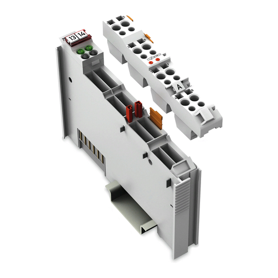
WAGO-I/O-SYSTEM 750 Device Description 753-501 2DO 24V DC 0,5A View Depiction of the I/O module with 753-110 Connector! Information on this pluggable connection pertains to the 753-110 Connector, which is not included with the I/O module. Figure 1: View Table 4: Legend for Figure “View”... -
Page 16: Connectors
Device Description WAGO-I/O-SYSTEM 750 753-501 2DO 24V DC 0,5A Connectors 3.2.1 Data Contacts/Internal Bus Communication between the fieldbus coupler/controller and the I/O modules as well as the system supply of the I/O modules is carried out via the internal bus. It is comprised of 6 data contacts, which are available as self-cleaning gold spring contacts. -
Page 17: Power Jumper Contacts/Field Supply
WAGO-I/O-SYSTEM 750 Device Description 753-501 2DO 24V DC 0,5A 3.2.2 Power Jumper Contacts/Field Supply Risk of injury due to sharp-edged blade contacts! The blade contacts are sharp-edged. Handle the I/O module carefully to prevent injury. The I/O module 753-501 has 3 self-cleaning power jumper contacts that supply and transmit power for the field side. -
Page 18: Cage Clamp
Device Description WAGO-I/O-SYSTEM 750 753-501 2DO 24V DC 0,5A Do not exceed maximum current via power jumper contacts! The maximum current to flow through the power jumper contacts is 10 A. Greater currents can damage the contacts. When configuring your system, ensure that this current is not exceeded. If exceeded, insert an additional supply module. -
Page 19: Display Elements
WAGO-I/O-SYSTEM 750 Device Description 753-501 2DO 24V DC 0,5A Display Elements Figure 5: Display Elements Table 7: Legend for Figure “Display Elements” Channel Designation State Function Output DO 1: Signal voltage “0” Status DO 1 Green Output DO 1: Signal voltage “1”... -
Page 20: Technical Data
Device Description WAGO-I/O-SYSTEM 750 753-501 2DO 24V DC 0,5A Technical Data 3.5.1 Device Data Table 8: Technical Data ‒ Device Width 12 mm Height (from upper edge of 35 DIN rail) 64 mm Depth 100 mm Weight approx. 47 g 3.5.2... -
Page 21: Connection
WAGO-I/O-SYSTEM 750 Device Description 753-501 2DO 24V DC 0,5A 3.5.5 Connection Table 12: Technical Data – Field Wiring ® Wire connection CAGE CLAMP Cross section 0.08 mm² ... 2.5 mm² / AWG 28 … 14 Stripped length 9 ... 10 mm / 0.37 in Table 13: Technical Data –... -
Page 22: Approvals
753-501 2DO 24V DC 0,5A Approvals More information about approvals. Detailed references to the approvals are listed in the document “Overview Approvals WAGO-I/O-SYSTEM 750”, which you can find via the internet under: www.wago.com > SERVICES > DOWNLOADS > Additional documentation and information on automation products > WAGO-I/O-SYSTEM 750 >... -
Page 23: Standards And Guidelines
WAGO-I/O-SYSTEM 750 Device Description 753-501 2DO 24V DC 0,5A The following ship approvals have been granted to the basic version of 753-501 I/O modules: ABS (American Bureau of Shipping) BV (Bureau Veritas) DNV (Det Norske Veritas) Class B GL (Germanischer Lloyd) Cat. -
Page 24: Process Image
Process Image WAGO-I/O-SYSTEM 750 753-501 2DO 24V DC 0,5A Process Image Table 16: Output Bits Bit 1 Bit 0 DO 2 DO 1 DO 1 Signal state DO 1 – digital output channel 1 DO 2 Signal state DO 2 – digital output channel 2... -
Page 25: Mounting
Don't forget the bus end module! Always plug a bus end module 750-600 onto the end of the fieldbus node! You must always use a bus end module at all fieldbus nodes with WAGO-I/O- SYSTEM 750 fieldbus couplers/controllers to guarantee proper data transfer. -
Page 26: Inserting And Removing Devices
Mounting WAGO-I/O-SYSTEM 750 753-501 2DO 24V DC 0,5A Inserting and Removing Devices Perform work on devices only if they are de-energized! Working on energized devices can damage them. Therefore, turn off the power supply before working on the devices. 5.2.1... -
Page 27: Removing The I/O Module
WAGO-I/O-SYSTEM 750 Mounting 753-501 2DO 24V DC 0,5A 5.2.2 Removing the I/O Module Remove pluggable connector! Before removing a 753 Series I/O Module from the node, you must first remove the pluggable connector from the module (see section “Connector Removal”)! Remove the I/O module from the node by pulling the release tab. -
Page 28: I/O Modules With Pluggable Wiring Level (Series 753)
Mounting WAGO-I/O-SYSTEM 750 753-501 2DO 24V DC 0,5A I/O Modules with Pluggable Wiring Level (Series 753) Series 753 I/O modules feature a pluggable connector for I/O wiring. This connector is simply plugged into the bottom of the module. The connector can be completely removed together with the wiring, simplifying replacement of defective modules from the assembly. -
Page 29: Coding
WAGO-I/O-SYSTEM 750 Mounting 753-501 2DO 24V DC 0,5A 5.3.1 Coding Coding using small plastic pins and sockets facilitates mating of the module with the appropriate connector. Insert the pin into the socket. Figure 13: Assembling the Coding Fingers Position the assembled coding fingers in the I/O module. Due to its design, each coding finger allows four different coding options (i.e.;... -
Page 30: Figure 16: "Sure Match" Coding Fingers
Mounting WAGO-I/O-SYSTEM 750 753-501 2DO 24V DC 0,5A When the connector is removed the sockets remain in the I/O module. The coded connector can only fit in the corresponding coded I/O module (see figures below). Figure 16: “Sure Match” Coding Fingers Manual Version 1.2.0... -
Page 31: Connector Removal
WAGO-I/O-SYSTEM 750 Mounting 753-501 2DO 24V DC 0,5A 5.3.2 Connector Removal Remove the connector from the I/O module by pulling the orange pull tab on the connector toward the top of the module. Figure 17: Pulling the Pull Tab The connector detaches from the module. -
Page 32: Connect Devices
Only one conductor may be connected to each CAGE CLAMP Do not connect more than one conductor at one single connection! If more than one conductor must be routed to one connection, these must be connected in an up-circuit wiring assembly, for example using WAGO feed- through terminals. Exception: If it is unavoidable to jointly connect 2 conductors, then you must use a ferrule to join the wires together. -
Page 33: Connection Examples
WAGO-I/O-SYSTEM 750 Connect Devices 753-501 2DO 24V DC 0,5A Connection Examples Depiction of the I/O module with 753-110 Connector! Information on this pluggable connection pertains to the 753-110 Connector, which is not included with the I/O module. 6.2.1 2-Conductor Connection, Ungrounded Figure 21: Connecting Diagram, 2-Conductor Connection, Ungrounded 6.2.2... -
Page 34: 3-Conductor Connection, Ungrounded
Connect Devices WAGO-I/O-SYSTEM 750 753-501 2DO 24V DC 0,5A 6.2.3 3-Conductor Connection, Ungrounded Figure 23: Connecting Diagram, 3-Conductor Connection, Ungrounded 6.2.4 3-Conductor Connection, Grounded Figure 24: Connecting Diagram, 3-Conductor Connection, Grounded Manual Version 1.2.0... -
Page 35: Using Interference-Free Variants Of I/O Modules In Safety Related Applications
WAGO-I/O-SYSTEM 750 Using Interference-Free Variants of I/O Modules in Safety Related Applications 753-501 2DO 24V DC 0,5A Using Interference-Free Variants of I/O Modules in Safety Related Applications The variant 753-501/xxx-8xx of the I/O module 753-501 (designation “... /R“ in the product name) is suited for use in interference-free safety circuits. -
Page 36: Important Notes
Using Interference-Free Variants of I/O Modules in Safety Related ApplicationsWAGO-I/O-SYSTEM 750 753-501 2DO 24V DC 0,5A Eins atz der rüc kwir kungsfrei en Digital ausg angs kl emme in Sic her heitsanwendungen Important Notes Use PELV supply only! Only a power supply unit with protective extra-low voltage (PELV) shall be used for the 24 V power supply. -
Page 37: Connecting The Io Module To Safety Switching Devices Or Safety Modules
WAGO-I/O-SYSTEM 750 Using Interference-Free Variants of I/O Modules in Safety Related Applications 753-501 2DO 24V DC 0,5A Connecting the IO Module to Safety Switching Devices or Safety Modules 7.2.1 General Structure When using the interference-free variant “…/xxx-8xx”of the IO module 753-501 in safety related applications, the modules belonging to a safety switching device shall be combined to form a potential group. -
Page 38: Examples Of Connection
Using Interference-Free Variants of I/O Modules in Safety Related ApplicationsWAGO-I/O-SYSTEM 750 753-501 2DO 24V DC 0,5A Eins atz der rüc kwir kungsfrei en Digital ausg angs kl emme in Sic her heitsanwendungen 7.2.2 Examples of Connection Two-channel Single-pole Power Supply Disconnection Figure 26: Two-channel Single-pole Disconnection Two-channel Double-pole Power Supply Disconnection Figure 27: Two-channel Double-pole Disconnection... -
Page 39: Use In Hazardous Environments
Use in Hazardous Environments 753-501 2DO 24V DC 0,5A Use in Hazardous Environments The WAGO-I/O-SYSTEM 750 (electrical equipment) is designed for use in Zone 2 hazardous areas. The following sections include both the general identification of components (devices) and the installation regulations to be observed. The individual subsections of the “Installation Regulations”... -
Page 40: Marking Configuration Examples
Use in Hazardous Environments WAGO-I/O-SYSTEM 750 753-501 2DO 24V DC 0,5A Marking Configuration Examples 8.1.1 Marking for Europe According to ATEX and IEC-Ex Figure 28: Side Marking Example for Approved I/O Modules According to ATEX and IECEx Figure 29: Text Detail – Marking Example for Approved I/O Modules According to ATEX and IECEx. -
Page 41: Table 17: Description Of Marking Example For Approved I/O Modules According To Atex And Iecex
WAGO-I/O-SYSTEM 750 Use in Hazardous Environments 753-501 2DO 24V DC 0,5A Table 17: Description of Marking Example for Approved I/O Modules According to ATEX and IECEx Printing on Text Description TÜV 07 ATEX 554086 X Approving authority and certificate numbers IECEx TUN 09.0001 X... -
Page 42: Figure 30: Side Marking Example For Approved Ex I I/O Modules According To Atex And Iecex
Use in Hazardous Environments WAGO-I/O-SYSTEM 750 753-501 2DO 24V DC 0,5A Figure 30: Side Marking Example for Approved Ex i I/O Modules According to ATEX and IECEx. Figure 31: Text Detail – Marking Example for Approved Ex i I/O Modules According to ATEX and IECEx. - Page 43 WAGO-I/O-SYSTEM 750 Use in Hazardous Environments 753-501 2DO 24V DC 0,5A Table 18: Description of Marking Example for Approved Ex i I/O Modules According to ATEX and IECEx Inscription Text Description TÜV 07 ATEX 554086 X Approving authority and certificate numbers IECEx TUN 09.0001X...
-
Page 44: Table 18: Description Of Marking Example For Approved Ex I I/O Modules According To Atex And Iecex
Use in Hazardous Environments WAGO-I/O-SYSTEM 750 753-501 2DO 24V DC 0,5A Table 18: Description of Marking Example for Approved Ex i I/O Modules According to ATEX and IECEx Gases Equipment group: All except mining 3(1)G Category 3 (Zone 2) equipment containing a safety... -
Page 45: Marking For America According To Nec 500
WAGO-I/O-SYSTEM 750 Use in Hazardous Environments 753-501 2DO 24V DC 0,5A 8.1.2 Marking for America According to NEC 500 Figure 32: Side Marking Example for I/O Modules According to NEC 500 Figure 33: Text Detail – Marking Example for Approved I/O Modules According to NEC 500... -
Page 46: Installation Regulations
Use in Hazardous Environments WAGO-I/O-SYSTEM 750 753-501 2DO 24V DC 0,5A Installation Regulations For the installation and operation of electrical equipment in hazardous areas, the valid national and international rules and regulations which are applicable at the installation location must be carefully followed. -
Page 47: Special Conditions For Safe Use (Atex Certificate Tüv 07 Atex 554086 X)
(ATEX Certificate TÜV 07 ATEX 554086 X) For use as Gc- or Dc-apparatus (in zone 2 or 22) the Field bus Independent I/O Modules WAGO-I/O-SYSTEM 750-*** shall be erected in an enclosure that fulfils the requirements of the applicable standards (see the marking) EN 60079-0, EN 60079-11, EN 60079-15 and EN 60079-31. -
Page 48: Special Conditions For Safe Use (Atex Certificate Tüv 12 Atex 106032 X)
(ATEX Certificate TÜV 12 ATEX 106032 X) For use as Gc- or Dc-apparatus (in zone 2 or 22) the Field bus Independent I/O Modules WAGO-I/O-SYSTEM 750-*** Ex i shall be erected in an enclosure that fulfils the requirements of the applicable standards (see the marking) EN 60079-0, EN 60079-11, EN 60079-15 and EN 60079-31. -
Page 49: Special Conditions For Safe Use (Iec-Ex Certificate Tun 09.0001 X)
(IEC-Ex Certificate TUN 09.0001 X) For use as Gc- or Dc-apparatus (in zone 2 or 22) the Field bus Independent I/O Modules WAGO-I/O-SYSTEM 750-*** shall be erected in an enclosure that fulfils the requirements of the applicable standards (see the marking) IEC 60079-0, IEC 60079-11, IEC 60079-15 and IEC 60079-31. -
Page 50: Special Conditions For Safe Use (Iec-Ex Certificate Iecex Tun 12.0039 X)
(IEC-Ex Certificate IECEx TUN 12.0039 X) For use as Gc- or Dc-apparatus (in zone 2 or 22) the Field bus independent I/O Modules WAGO-I/O-SYSTEM 750-*** Ex i shall be erected in an enclosure that fulfils the requirements of the applicable standards (see the marking) IEC 60079-0, IEC 60079-11, IEC 60079-15, IEC 60079-31. -
Page 51: Special Conditions For Safe Use According To Ansi/Isa
WAGO-I/O-SYSTEM 750 Use in Hazardous Environments 753-501 2DO 24V DC 0,5A 8.2.5 Special Conditions for Safe Use According to ANSI/ISA 12.12.01 “This equipment is suitable for use in Class I, Division 2, Groups A, B, C, D or non-hazardous locations only.”... -
Page 52: List Of Figures
List of Figures WAGO-I/O-SYSTEM 750 753-501 2DO 24V DC 0,5A List of Figures Figure 1: View ....................... 15 Figure 2: Data Contacts ..................16 Figure 3: Power Jumper Contacts ................. 17 ® Figure 4: CAGE CLAMP Connectors..............18 Figure 5: Display Elements ................... 19 Figure 6: Schematic Diagram ................ -
Page 53: List Of Tables
WAGO-I/O-SYSTEM 750 List of Tables 753-501 2DO 24V DC 0,5A List of Tables Table 1: Variants ..................... 5 Table 2: Number Notation ..................8 Table 3: Font Conventions ..................8 Table 4: Legend for Figure “View” ..............15 Table 5: Legend for Figure “Power Jumper Contacts” ......... 17 ®... - Page 54 WAGO Kontakttechnik GmbH & Co. KG Postfach 2880 • D-32385 Minden Hansastraße 27 • D-32423 Minden Phone: 05 71/8 87 – 0 Fax: 05 71/8 87 – 1 69 E-Mail: info@wago.com Internet: http://www.wago.com...
Need help?
Do you have a question about the I/O-SYSTEM 750 753-501 and is the answer not in the manual?
Questions and answers