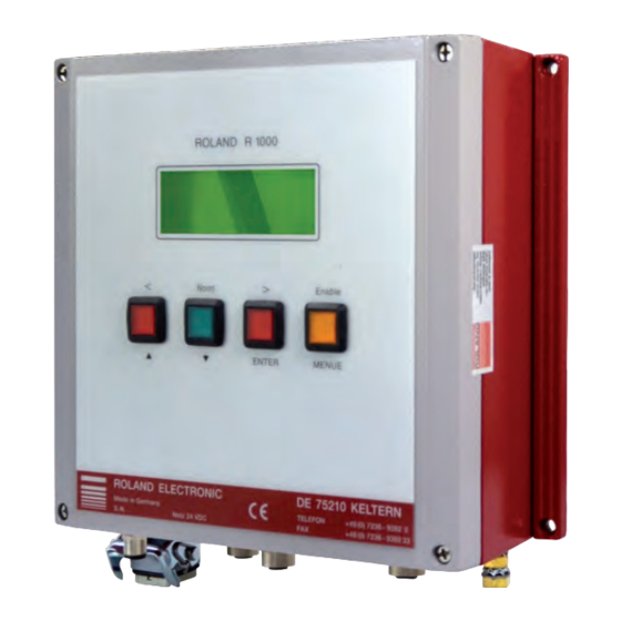
Roland R1000 Series Manual
Double sheet detector with integrated fieldbus interface
Hide thumbs
Also See for R1000 Series:
- Manual (162 pages) ,
- Owner's manual (80 pages) ,
- User manual (4 pages)
Table of Contents
Advertisement
Quick Links
Double Sheet Detector
R1000-series E20
with integrated fieldbus interface
Pos : 1 /D oppelbl ec h/Geräte/E20/Dec kbl att/D ec kbl att @ 0\mod_1173195768953_501.doc @ 3188
Electro magnetic principles –
microcontroller based
Single – sided contact double sheet control of ferrous materials
No force after measurement
4 exchangeable sensors for double sheet control of 0.1 – 12 mm (.004 - .472 inch) sheet
thickness
Optional version 4P allows connection of up to four identical sensors
►
Programmable for 255 different sheet thicknesses and materials
►
Calibration without sheet samples
►
Digital display of sheet thickness and operational parameters
►
Monitoring of over-gauge and under-gauge limit
►
Monitoring of operating voltage and sensor gap
►
Galvanically isolated 3-bit input interface and 5-bit output interface
►
Integrated fieldbus interface with process and parameter interface
− Profibus DP
− ControlNet
− DeviceNet
− Interbus-S
− CanOpen
− ProfiNet IO
− CC-Link
− EtherNet/IP
− EtherCAT
DOUBLE SHEET CONTROL E20
Advertisement
Table of Contents

Subscribe to Our Youtube Channel
Related Manuals for Roland R1000 Series


Summary of Contents for Roland R1000 Series
- Page 1 DOUBLE SHEET CONTROL E20 Double Sheet Detector R1000-series E20 with integrated fieldbus interface Pos : 1 /D oppelbl ec h/Geräte/E20/Dec kbl att/D ec kbl att @ 0\mod_1173195768953_501.doc @ 3188 Electro magnetic principles – microcontroller based Single – sided contact double sheet control of ferrous materials No force after measurement 4 exchangeable sensors for double sheet control of 0.1 –...
- Page 2 2015 ROLAND ELECTRONIC GmbH Otto-Maurer-Str. 17 DE 75210 Keltern All rights on this document are at Roland Electronic GmbH. Reproduction (also partly), electronical coverage, translation, transmission to third parties, only with our prior permission. Subject to change without further notice.
-
Page 3: Table Of Contents
Configuration menu .......................... 105 General information regarding the configuration ................107 Changing, setting-up or checking the configuration ................. 107 ROLAND ELECTRONIC GmbH · Otto-Maurer-Str. 17 · DE 75210 Keltern · Phone +49 (0)7236-9392-0 · Fax +49 (0)7236-9392-33... - Page 4 Cable plugs and cable sockets ....................149 12.6 Other accessories ........................150 Appendix ............................151 13.1 System configuration form ......................151 ROLAND ELECTRONIC GmbH · Otto-Maurer-Str. 17 · DE 75210 Keltern · Phone +49 (0)7236-9392-0 · Fax +49 (0)7236-9392-33...
-
Page 5: Declaration Of Conformity According To Ec Directives
The safety instructions and warnings must be observed. ISO 9001 : 2008 Reg.-no. 5152 QM08 ROLAND ELECTRONIC GmbH · Otto-Maurer-Str. 17 · DE 75210 Keltern · Phone +49 (0)7236-9392-0 · Fax +49 (0)7236-9392-33... - Page 6 Manual Double Sheet Detector R1000 series UDK20 with integrated fieldbus interface Safety advices B0048191 / Rev. 1.5 Blank page ROLAND ELECTRONIC GmbH · Otto-Maurer-Str. 17 · DE 75210 Keltern · Phone +49 (0)7236-9392-0 · Fax +49 (0)7236-9392-33...
-
Page 7: Safety Advices
Warning When connecting or disconnecting the sensor plug you must stop measurement! Non-observance can result in a damage of the sensor! ROLAND ELECTRONIC GmbH · Otto-Maurer-Str. 17 · DE 75210 Keltern · Phone +49 (0)7236-9392-0 · Fax +49 (0)7236-9392-33... -
Page 8: Intended Use
Field bus specific expression Master Scanner Slave ControlNet adapter / node Baud rate Data rate Bus address Mac ID / node address ROLAND ELECTRONIC GmbH · Otto-Maurer-Str. 17 · DE 75210 Keltern · Phone +49 (0)7236-9392-0 · Fax +49 (0)7236-9392-33... -
Page 9: Technical Data
In case of inductive load a coil protection diode should be used. Otherwise the signal output could be destroyed by the excess voltage generated by switching the inductive load off. ROLAND ELECTRONIC GmbH · Otto-Maurer-Str. 17 · DE 75210 Keltern · Phone +49 (0)7236-9392-0 · Fax +49 (0)7236-9392-33... - Page 10 CanOpen - interface, according to DS301 v4.02 compliant ProfiNet IO – interface CC-Link V1 EtherNet/IP EtherCAT ROLAND ELECTRONIC GmbH · Otto-Maurer-Str. 17 · DE 75210 Keltern · Phone +49 (0)7236-9392-0 · Fax +49 (0)7236-9392-33...
-
Page 11: Versions Of The Control Unit Udk20
Unit for connection of max. two sensors, in industrial enclosure, with data backup via Fieldbus or serial port • UDK20-2PW-xx-S-FP: Unit as previous, but for front plate mounting ROLAND ELECTRONIC GmbH · Otto-Maurer-Str. 17 · DE 75210 Keltern · Phone +49 (0)7236-9392-0 · Fax +49 (0)7236-9392-33... -
Page 12: Sensors
30 – 140 °F Class of protection: IP65 Weight: approx. 0.5 kg 1.1 lbs Sensor cable: pluggable Related to single sheet thickness ROLAND ELECTRONIC GmbH · Otto-Maurer-Str. 17 · DE 75210 Keltern · Phone +49 (0)7236-9392-0 · Fax +49 (0)7236-9392-33... -
Page 13: Sensor Performance Data (Measuring Time) For Ferrous (Fe) Material
The advantage in measuring time is significant, if the thickness of material is considerably lower than the measuring range of the sensor. ROLAND ELECTRONIC GmbH · Otto-Maurer-Str. 17 · DE 75210 Keltern · Phone +49 (0)7236-9392-0 · Fax +49 (0)7236-9392-33... -
Page 14: Sensor Data For Non-Ferrous (Nf) Material
2 sensors (in sequencer mode). Material Conductivity (MS) Max. thickness for single sheet (mm) Austenite 1.41 Bronze Zinc 16.3 AL-Alloy 18.2 AL-Alloy 25.2 34.2 CU-Alloy 57.5 ROLAND ELECTRONIC GmbH · Otto-Maurer-Str. 17 · DE 75210 Keltern · Phone +49 (0)7236-9392-0 · Fax +49 (0)7236-9392-33... -
Page 15: Sensor Data (Air Gap)
Max. air gap between first and second sheet (2nd air gap) PW42AGS [mm] The data apply for a set upper limit of 120%. ROLAND ELECTRONIC GmbH · Otto-Maurer-Str. 17 · DE 75210 Keltern · Phone +49 (0)7236-9392-0 · Fax +49 (0)7236-9392-33... -
Page 16: Sensor Cables
/ violet blue brown 1 mm² brown white 1 mm² green Enclosure blank (Shield) Fig. 4: Sensor cable SCPWS ROLAND ELECTRONIC GmbH · Otto-Maurer-Str. 17 · DE 75210 Keltern · Phone +49 (0)7236-9392-0 · Fax +49 (0)7236-9392-33... - Page 17 The cable is drag cable suitable and oil resistant. Cable type: • Superflex (C)Y PURKOMBI 2 x 1,0 mm² + 4 x 2 x 0,25 mm² ROLAND ELECTRONIC GmbH · Otto-Maurer-Str. 17 · DE 75210 Keltern · Phone +49 (0)7236-9392-0 · Fax +49 (0)7236-9392-33...
- Page 18 Sensor cable extensions A sensor cable extension can be relatively easy made. For this a SCPWS-GG or SCPWS-GW cable is always needed. ROLAND ELECTRONIC GmbH · Otto-Maurer-Str. 17 · DE 75210 Keltern · Phone +49 (0)7236-9392-0 · Fax +49 (0)7236-9392-33...
- Page 19 The standard length is 5 meter. Note For the connection of the SSBUDK10 to the sensor PW42AGS the SCPWSGG or SCPWS-GW are used. ROLAND ELECTRONIC GmbH · Otto-Maurer-Str. 17 · DE 75210 Keltern · Phone +49 (0)7236-9392-0 · Fax +49 (0)7236-9392-33...
- Page 20 Manual Double Sheet Detector R1000 series UDK20 with integrated fieldbus interface System description B0048191 / Rev. 1.5 Blank page ROLAND ELECTRONIC GmbH · Otto-Maurer-Str. 17 · DE 75210 Keltern · Phone +49 (0)7236-9392-0 · Fax +49 (0)7236-9392-33...
-
Page 21: System Description
• the air gap between sensor and material surface • the magnetical characteristics of the material • the tolerance in material thickness ROLAND ELECTRONIC GmbH · Otto-Maurer-Str. 17 · DE 75210 Keltern · Phone +49 (0)7236-9392-0 · Fax +49 (0)7236-9392-33... -
Page 22: Control Unit
Program parameters contain items which are material and job depending, and enable individual adaptation to the measuring task. ROLAND ELECTRONIC GmbH · Otto-Maurer-Str. 17 · DE 75210 Keltern · Phone +49 (0)7236-9392-0 · Fax +49 (0)7236-9392-33... - Page 23 “Sensor type“ At the time of editing the sensor type PW42A is available. For this sensor a characteristical curve for linearization purposes exists. ROLAND ELECTRONIC GmbH · Otto-Maurer-Str. 17 · DE 75210 Keltern · Phone +49 (0)7236-9392-0 · Fax +49 (0)7236-9392-33...
- Page 24 “Teach-In 0-, 1-sheet“. Default setting is “no“. • The external adjust may only be performed under supervision of an operator. ROLAND ELECTRONIC GmbH · Otto-Maurer-Str. 17 · DE 75210 Keltern · Phone +49 (0)7236-9392-0 · Fax +49 (0)7236-9392-33...
- Page 25 AUTO must be chosen. For all settings (except for FE) a Teach-In is required. “Nominal thickness“ Changes the nominal thickness. It can be shown in mm or inch. Default setting either 0,03mm or 0,001 inch. ROLAND ELECTRONIC GmbH · Otto-Maurer-Str. 17 · DE 75210 Keltern · Phone +49 (0)7236-9392-0 · Fax +49 (0)7236-9392-33...
- Page 26 The value “on“ indicates that a Teach-In is currently being performed. • The value “without“ indicates that a Teach-In is not necessarily required. This item appears only for “Material“ setting “FE“. ROLAND ELECTRONIC GmbH · Otto-Maurer-Str. 17 · DE 75210 Keltern · Phone +49 (0)7236-9392-0 · Fax +49 (0)7236-9392-33...
-
Page 27: Application Samples
B0048191 / Rev. 1.5 Application samples The following are two typical application examples for the use of the UDK20. UDK20-xx-S with one Sensor ROLAND ELECTRONIC GmbH · Otto-Maurer-Str. 17 · DE 75210 Keltern · Phone +49 (0)7236-9392-0 · Fax +49 (0)7236-9392-33... - Page 28 The optional Sensor Switch Box (SSB) permits connecting of max. four sensors PW42AGS to one UDK20-xx-S(-FP). These sensors cannot be operated parallel via SSB but only sequentially via program switchover. ROLAND ELECTRONIC GmbH · Otto-Maurer-Str. 17 · DE 75210 Keltern · Phone +49 (0)7236-9392-0 · Fax +49 (0)7236-9392-33...
- Page 29 The switching of the sensors can be made as follows: with the so-called sequencer mode (automatic switching by the unit) by program switching ROLAND ELECTRONIC GmbH · Otto-Maurer-Str. 17 · DE 75210 Keltern · Phone +49 (0)7236-9392-0 · Fax +49 (0)7236-9392-33...
- Page 30 In addition to the selection by sensor number (see system configuration "number of sensors"), the following sequences for the selection are available: Sensor 1 + Sensor 2 ROLAND ELECTRONIC GmbH · Otto-Maurer-Str. 17 · DE 75210 Keltern · Phone +49 (0)7236-9392-0 · Fax +49 (0)7236-9392-33...
- Page 31 3. Analysis result of programm 1 4. Select programm 2 5. Measuring programm 2 6. Analysis result of programm 2 1.0 mm 0.7 mm ROLAND ELECTRONIC GmbH · Otto-Maurer-Str. 17 · DE 75210 Keltern · Phone +49 (0)7236-9392-0 · Fax +49 (0)7236-9392-33...
- Page 32 Manual Double Sheet Detector R1000 series UDK20 with integrated fieldbus interface Mounting B0048191 / Rev. 1.5 Blank page ROLAND ELECTRONIC GmbH · Otto-Maurer-Str. 17 · DE 75210 Keltern · Phone +49 (0)7236-9392-0 · Fax +49 (0)7236-9392-33...
-
Page 33: Mounting
Strong vibrations and additional heat can damage the control unit. In case of panel or operator consoles the front panel version should be used. ROLAND ELECTRONIC GmbH · Otto-Maurer-Str. 17 · DE 75210 Keltern · Phone +49 (0)7236-9392-0 · Fax +49 (0)7236-9392-33... -
Page 34: Dimensions Of The System
All dimensions are in mm. Tolerance: ±0.4 mm Fig. 8: Dimensions of the wall mount enclosure - front view ROLAND ELECTRONIC GmbH · Otto-Maurer-Str. 17 · DE 75210 Keltern · Phone +49 (0)7236-9392-0 · Fax +49 (0)7236-9392-33... - Page 35 A minimum depth of 120 mm is required for connecting the plugs. All dimensions are in mm. Tolerance: ±0.4 mm Fig. 9: Dimensions of the front panel enclosure -front view ROLAND ELECTRONIC GmbH · Otto-Maurer-Str. 17 · DE 75210 Keltern · Phone +49 (0)7236-9392-0 · Fax +49 (0)7236-9392-33...
- Page 36 B0048191 / Rev. 1.5 All dimensions are in mm. Tolerance: ±0.4 mm Fig. 10: Dimensions of the front panel enclosure -front view ROLAND ELECTRONIC GmbH · Otto-Maurer-Str. 17 · DE 75210 Keltern · Phone +49 (0)7236-9392-0 · Fax +49 (0)7236-9392-33...
-
Page 37: Mounting Of Sensors
Only if this fault condition is eliminated should sheet processing be allowed to continue. ROLAND ELECTRONIC GmbH · Otto-Maurer-Str. 17 · DE 75210 Keltern · Phone +49 (0)7236-9392-0 · Fax +49 (0)7236-9392-33... - Page 38 Ideally the spring mounted bracket should be pre-loaded in order to ensure that the sensor is presented perpendicular to the sheet even under dynamic conditions. ROLAND ELECTRONIC GmbH · Otto-Maurer-Str. 17 · DE 75210 Keltern · Phone +49 (0)7236-9392-0 · Fax +49 (0)7236-9392-33...
- Page 39 Never use sensor bracket as a lifting suction cup ! (except sheet is smaller than area of 3 suction cups) Fig. 11: Overview Sensor bracket ROLAND ELECTRONIC GmbH · Otto-Maurer-Str. 17 · DE 75210 Keltern · Phone +49 (0)7236-9392-0 · Fax +49 (0)7236-9392-33...
- Page 40 View in direction "A" without sensor ø20.5 All Dimensions are in mm. Tolerance: ±0.4 mm. Fig. 12: Spring loaded sensor bracket SH42GS ROLAND ELECTRONIC GmbH · Otto-Maurer-Str. 17 · DE 75210 Keltern · Phone +49 (0)7236-9392-0 · Fax +49 (0)7236-9392-33...
- Page 41 4.3.3.1 Spring travel of SHS42GS ausgefedert (Zug) unbelastet eingefedert (Druck) extracted (pull) unstressed retracted (pressure) Fig. 13: Spring travel for SHS42GS ROLAND ELECTRONIC GmbH · Otto-Maurer-Str. 17 · DE 75210 Keltern · Phone +49 (0)7236-9392-0 · Fax +49 (0)7236-9392-33...
- Page 42 Connection 1/4" ø20.5 All Dimensions are in mm. Tolerance: ± 0.4 mm. Fig. 14: Spring loaded sensor bracket SHS42GS with flat suction cup ROLAND ELECTRONIC GmbH · Otto-Maurer-Str. 17 · DE 75210 Keltern · Phone +49 (0)7236-9392-0 · Fax +49 (0)7236-9392-33...
- Page 43 The holder may not carry loads. Only small, light weighted parts can be directly transported with the sensor holder. 110 Ø Fig. 15: Sensor bracket SHX42 ROLAND ELECTRONIC GmbH · Otto-Maurer-Str. 17 · DE 75210 Keltern · Phone +49 (0)7236-9392-0 · Fax +49 (0)7236-9392-33...
- Page 44 Pull the rubber disc over the lower edge. Pay attention for undamaged sealing lips at the inner and outer edge as well as for uniform projection of the sealing edge. The gasket can be bilaterally used. ROLAND ELECTRONIC GmbH · Otto-Maurer-Str. 17 · DE 75210 Keltern · Phone +49 (0)7236-9392-0 · Fax +49 (0)7236-9392-33...
- Page 45 Clamping bracket SHX-AZ2-25 For fixing the sensor bracket SHX42 to swivel arms with 25 mm clamp collar. Fig. 17: Clamping bracket SHX-AZ2-25 ROLAND ELECTRONIC GmbH · Otto-Maurer-Str. 17 · DE 75210 Keltern · Phone +49 (0)7236-9392-0 · Fax +49 (0)7236-9392-33...
- Page 46 Ø6mm, outerØ8 mm : unloaded 128 ± 1 : unloaded 90 ± 1 : Spring travel: appr. 37 Fig. 18: Sensor bracket SHS42G-FB ROLAND ELECTRONIC GmbH · Otto-Maurer-Str. 17 · DE 75210 Keltern · Phone +49 (0)7236-9392-0 · Fax +49 (0)7236-9392-33...
- Page 47 The clamping bracket SHK can be used for the mounting of the spring loaded sensor brackets SHS...GS or SH...GS. All Dimensions are in mm. Tolerance: ± 0.2 mm. Fig. 19: Clamping bracket SHK ROLAND ELECTRONIC GmbH · Otto-Maurer-Str. 17 · DE 75210 Keltern · Phone +49 (0)7236-9392-0 · Fax +49 (0)7236-9392-33...
- Page 48 The second sheet clings to the first sheet, perhaps by stamping residuals. Faulty! Fault prone control in a bucket. An air gap exists between bended sheets. Fig. 20: Incorrect mounting of the PW-sensors ROLAND ELECTRONIC GmbH · Otto-Maurer-Str. 17 · DE 75210 Keltern · Phone +49 (0)7236-9392-0 · Fax +49 (0)7236-9392-33...
- Page 49 Sensor-Switch-Box and the sensors should be under visual control of the operating personnel. All Dimensions are in mm. Tolerance: ± 0.4 mm. Fig. 21: Sensor-Switch-Box SSBUDK10 ROLAND ELECTRONIC GmbH · Otto-Maurer-Str. 17 · DE 75210 Keltern · Phone +49 (0)7236-9392-0 · Fax +49 (0)7236-9392-33...
-
Page 50: Automatic Tool Changer
After each tool change it is required to perform a zero set command. Attention Incorrect wiring may destroy the control unit or the sensor. ROLAND ELECTRONIC GmbH · Otto-Maurer-Str. 17 · DE 75210 Keltern · Phone +49 (0)7236-9392-0 · Fax +49 (0)7236-9392-33... -
Page 51: Electrical Installation
If the whole plug becomes turned, the locking facility and the contact pins will break and the connector will become useless. Never mis-use parts of a connector as holder for mounting the counterpart. ROLAND ELECTRONIC GmbH · Otto-Maurer-Str. 17 · DE 75210 Keltern · Phone +49 (0)7236-9392-0 · Fax +49 (0)7236-9392-33... -
Page 52: Configuration Of Connectors
Power supply connection / opto coupler input The fieldbus connections comply with the according type of Fieldbus (For details refer to chapter 5.2.3) ROLAND ELECTRONIC GmbH · Otto-Maurer-Str. 17 · DE 75210 Keltern · Phone +49 (0)7236-9392-0 · Fax +49 (0)7236-9392-33... - Page 53 Power supply connection / opto coupler input The fieldbus connections comply with the according type of Fieldbus (For details refer to chapter 5.2.3) ROLAND ELECTRONIC GmbH · Otto-Maurer-Str. 17 · DE 75210 Keltern · Phone +49 (0)7236-9392-0 · Fax +49 (0)7236-9392-33...
- Page 54 Fig. 23: Cable SM8KRS232D9S Warning When connecting or disconnecting the sensor plug you must stop measurement! Non-observance can result in a damage of the sensor! ROLAND ELECTRONIC GmbH · Otto-Maurer-Str. 17 · DE 75210 Keltern · Phone +49 (0)7236-9392-0 · Fax +49 (0)7236-9392-33...
- Page 55 5th optocoupler output Warning When connecting or disconnecting the sensor plug you must stop measurement! Non-observance can result in a damage of the sensor! ROLAND ELECTRONIC GmbH · Otto-Maurer-Str. 17 · DE 75210 Keltern · Phone +49 (0)7236-9392-0 · Fax +49 (0)7236-9392-33...
- Page 56 The corresponding cable plugs are not within the scope of supply. Connector C1 (ControlNet output) Connector C2 (ControlNet input) Allocation of ControlNet connector Fieldbus type Connector C1 "A" Connector C2 "B" ControlNet ROLAND ELECTRONIC GmbH · Otto-Maurer-Str. 17 · DE 75210 Keltern · Phone +49 (0)7236-9392-0 · Fax +49 (0)7236-9392-33...
- Page 57 CAN High Pin 5 CAN Low View: plug side View: plug side Suppliers / types / notes: Binder, type 715 (A-coded) and others ROLAND ELECTRONIC GmbH · Otto-Maurer-Str. 17 · DE 75210 Keltern · Phone +49 (0)7236-9392-0 · Fax +49 (0)7236-9392-33...
- Page 58 Pin 4 CAN_H Pin 5 CAN_H View: plug side View: plug side Suppliers / types / notes: Binder, type 715 (A-coded) and others ROLAND ELECTRONIC GmbH · Otto-Maurer-Str. 17 · DE 75210 Keltern · Phone +49 (0)7236-9392-0 · Fax +49 (0)7236-9392-33...
- Page 59 Pin 4 RD – View: Plug enclosure Shield Plug side The corresponding cable plugs are part of the standard scope of supply. ROLAND ELECTRONIC GmbH · Otto-Maurer-Str. 17 · DE 75210 Keltern · Phone +49 (0)7236-9392-0 · Fax +49 (0)7236-9392-33...
- Page 60 The corresponding cable plugs are part of the standard The corresponding cable plugs are not within the scope scope of supply. of supply. ROLAND ELECTRONIC GmbH · Otto-Maurer-Str. 17 · DE 75210 Keltern · Phone +49 (0)7236-9392-0 · Fax +49 (0)7236-9392-33...
- Page 61 1.5 mm² cross section. Attention The earth ground/central machine ground must not be connected to + 24 VDC. ROLAND ELECTRONIC GmbH · Otto-Maurer-Str. 17 · DE 75210 Keltern · Phone +49 (0)7236-9392-0 · Fax +49 (0)7236-9392-33...
- Page 62 (for power requirements refer to chapter 2.1). Attention The earth ground/central machine ground must not be connected to + 24 VDC. ROLAND ELECTRONIC GmbH · Otto-Maurer-Str. 17 · DE 75210 Keltern · Phone +49 (0)7236-9392-0 · Fax +49 (0)7236-9392-33...
- Page 63 Measurement start signal can be issued either via the process channel or via an optocoupler. Simultaneous measurement start signals result in fault messages. ROLAND ELECTRONIC GmbH · Otto-Maurer-Str. 17 · DE 75210 Keltern · Phone +49 (0)7236-9392-0 · Fax +49 (0)7236-9392-33...
-
Page 64: Connecting Diagram - Examples
When a disconnection point is requested then 2 cables of type SCPWS-xx can be directly connected! Fig. 24: UDK20 with one PW42AGS sensor ROLAND ELECTRONIC GmbH · Otto-Maurer-Str. 17 · DE 75210 Keltern · Phone +49 (0)7236-9392-0 · Fax +49 (0)7236-9392-33... - Page 65 Pin 7 brown Pin 8 white, 1 mm² Pin 9 green Enclosure blank (Shield) Fig. 25: UDK20 with SSBUDK10 and four PW42AGS sensors ROLAND ELECTRONIC GmbH · Otto-Maurer-Str. 17 · DE 75210 Keltern · Phone +49 (0)7236-9392-0 · Fax +49 (0)7236-9392-33...
- Page 66 When a disconnection point is requested then 2 cables of type SCPWS-xx can be directly connected! Fig. 26: UDK20-2PW with two PW42AGS sensors ROLAND ELECTRONIC GmbH · Otto-Maurer-Str. 17 · DE 75210 Keltern · Phone +49 (0)7236-9392-0 · Fax +49 (0)7236-9392-33...
-
Page 67: Internal Wiring Of The Sensor-Switch-Box Ssbudk10
Control signal brown Pin 4 0 VDC yellow Pin 5 + 24 VDC grey Fig. 27: Internal wiring of the Sensor-Switch-Box SSBUDK10 ROLAND ELECTRONIC GmbH · Otto-Maurer-Str. 17 · DE 75210 Keltern · Phone +49 (0)7236-9392-0 · Fax +49 (0)7236-9392-33... - Page 68 Manual Double Sheet Detector R1000 series UDK20 with integrated fieldbus interface Communication with the PLC B0048191 / Rev. 1.5 Blank page ROLAND ELECTRONIC GmbH · Otto-Maurer-Str. 17 · DE 75210 Keltern · Phone +49 (0)7236-9392-0 · Fax +49 (0)7236-9392-33...
-
Page 69: Communication With The Plc
Note The messages are regularly updated and enhanced. It is therefore possible that there are deviations to the messages described here. ROLAND ELECTRONIC GmbH · Otto-Maurer-Str. 17 · DE 75210 Keltern · Phone +49 (0)7236-9392-0 · Fax +49 (0)7236-9392-33... -
Page 70: Data Transmission Communication
Byte S23 The R1000 is controlled by the process channel and via the parameter channel all systems and program data are accessible. ROLAND ELECTRONIC GmbH · Otto-Maurer-Str. 17 · DE 75210 Keltern · Phone +49 (0)7236-9392-0 · Fax +49 (0)7236-9392-33... -
Page 71: Process Channel
Measuring value, thickness sensor 1 Control signal sensor 2 Measuring value, thickness sensor 2 Measuring value, thickness sensor 2 free free free free free free ROLAND ELECTRONIC GmbH · Otto-Maurer-Str. 17 · DE 75210 Keltern · Phone +49 (0)7236-9392-0 · Fax +49 (0)7236-9392-33... - Page 72 If only the 1-sheet is present, then the “summary output“ is 1-sheet • Otherwise the “summary output“ is 0-sheet If the results of individual sensors are required, then interrogate bytes 12-23. ROLAND ELECTRONIC GmbH · Otto-Maurer-Str. 17 · DE 75210 Keltern · Phone +49 (0)7236-9392-0 · Fax +49 (0)7236-9392-33...
- Page 73 14.1 14.2 14.3 Low byte thickness value (sensor 1) 14.4 14.5 14.6 14.7 2), 3) Footnotes see Table “Bytes 21 to 23” ROLAND ELECTRONIC GmbH · Otto-Maurer-Str. 17 · DE 75210 Keltern · Phone +49 (0)7236-9392-0 · Fax +49 (0)7236-9392-33...
- Page 74 17.1 17.2 17.3 Low byte thickness value (sensor 2) 17.4 17.5 17.6 17.7 2), 3) Footnotes see Table “Bytes 21 to 23” ROLAND ELECTRONIC GmbH · Otto-Maurer-Str. 17 · DE 75210 Keltern · Phone +49 (0)7236-9392-0 · Fax +49 (0)7236-9392-33...
- Page 75 18.2 18.3 18.4 18.5 18.6 18.7 19.0 19.1 19.2 19.3 19.4 19.5 19.6 19.7 20.0 20.1 20.2 20.3 20.4 20.5 20.6 20.7 ROLAND ELECTRONIC GmbH · Otto-Maurer-Str. 17 · DE 75210 Keltern · Phone +49 (0)7236-9392-0 · Fax +49 (0)7236-9392-33...
- Page 76 In the following timing diagrams all outputs and inputs via the bus are designated as BOUT and BIN, in contrast, the opto coupler interface uses OUT or IN. ROLAND ELECTRONIC GmbH · Otto-Maurer-Str. 17 · DE 75210 Keltern · Phone +49 (0)7236-9392-0 · Fax +49 (0)7236-9392-33...
- Page 77 If the recovery time is less than twice the measuring time, the sensor will warm up and the measuring value will drift. ROLAND ELECTRONIC GmbH · Otto-Maurer-Str. 17 · DE 75210 Keltern · Phone +49 (0)7236-9392-0 · Fax +49 (0)7236-9392-33...
- Page 78 These timing periods can vary with different transmission rates and bus systems. The cycle time of the PLC has not been taken into account. ROLAND ELECTRONIC GmbH · Otto-Maurer-Str. 17 · DE 75210 Keltern · Phone +49 (0)7236-9392-0 · Fax +49 (0)7236-9392-33...
- Page 79 Additional recovery time of 0.5 seconds (for FE-material) In case of “Function fault“ = 1 “Function result“ will sometimes remain at 0. ROLAND ELECTRONIC GmbH · Otto-Maurer-Str. 17 · DE 75210 Keltern · Phone +49 (0)7236-9392-0 · Fax +49 (0)7236-9392-33...
- Page 80 Bit 5 Bit 4 Bit 3 Bit 2 Bit 1 Bit 0 … … … … … … … … … not used ROLAND ELECTRONIC GmbH · Otto-Maurer-Str. 17 · DE 75210 Keltern · Phone +49 (0)7236-9392-0 · Fax +49 (0)7236-9392-33...
- Page 81 The cycle time of the PLC has not been taken into account. In case of “Function fault“ = 1 “Function result“ will sometimes remain at 0. ROLAND ELECTRONIC GmbH · Otto-Maurer-Str. 17 · DE 75210 Keltern · Phone +49 (0)7236-9392-0 · Fax +49 (0)7236-9392-33...
- Page 82 These timing periods can vary with different transmission rates and bus systems. The cycle time of the PLC has not been taken into account. ROLAND ELECTRONIC GmbH · Otto-Maurer-Str. 17 · DE 75210 Keltern · Phone +49 (0)7236-9392-0 · Fax +49 (0)7236-9392-33...
- Page 83 The cycle time of the PLC has not been taken into account. In case of “Function fault“ = 1 “Function result“ will sometimes remain at 0. ROLAND ELECTRONIC GmbH · Otto-Maurer-Str. 17 · DE 75210 Keltern · Phone +49 (0)7236-9392-0 · Fax +49 (0)7236-9392-33...
- Page 84 The cycle time of the PLC has not been taken into account. In case of “Function fault“ = 1 “Function result“ will sometimes remain at 0. ROLAND ELECTRONIC GmbH · Otto-Maurer-Str. 17 · DE 75210 Keltern · Phone +49 (0)7236-9392-0 · Fax +49 (0)7236-9392-33...
- Page 85 The cycle time of the PLC has not been taken into account. In case of “Function fault“ = 1 “Function result“ will sometimes remain at 0. ROLAND ELECTRONIC GmbH · Otto-Maurer-Str. 17 · DE 75210 Keltern · Phone +49 (0)7236-9392-0 · Fax +49 (0)7236-9392-33...
-
Page 86: Parameter Channel
If an access is not allowed and therefore, the service cannot be executed, then the R1000 declares this action a collision. ROLAND ELECTRONIC GmbH · Otto-Maurer-Str. 17 · DE 75210 Keltern · Phone +49 (0)7236-9392-0 · Fax +49 (0)7236-9392-33... - Page 87 The application data bytes 0 to 3 contain the data which can be transmitted. Application data bytes Meaning Application data byte 0 - 3 Notes Application data The 4 bytes include the application data ROLAND ELECTRONIC GmbH · Otto-Maurer-Str. 17 · DE 75210 Keltern · Phone +49 (0)7236-9392-0 · Fax +49 (0)7236-9392-33...
- Page 88 The collision bit can be deleted with one of the following services: Close parameter channel, Empty service or Reset parameter channel. ROLAND ELECTRONIC GmbH · Otto-Maurer-Str. 17 · DE 75210 Keltern · Phone +49 (0)7236-9392-0 · Fax +49 (0)7236-9392-33...
- Page 89 A collision bit is set if reading cannot be executed. Instead of application data the default number is transmitted, see “6.4.8 Reset faulty access“. ROLAND ELECTRONIC GmbH · Otto-Maurer-Str. 17 · DE 75210 Keltern · Phone +49 (0)7236-9392-0 · Fax +49 (0)7236-9392-33...
- Page 90 If the service “Empty service“ cannot be executed, the collision bit is set (remains set). In place of the application data a fault code is transmitted, see section “6.4.8 Reset faulty access“. ROLAND ELECTRONIC GmbH · Otto-Maurer-Str. 17 · DE 75210 Keltern · Phone +49 (0)7236-9392-0 · Fax +49 (0)7236-9392-33...
- Page 91 However the parameter channel is thereby closed. 6.4.9 Listing of parameter channel commands A list with all parameter channel commands is specified in chapter “11.3 ROLAND ELECTRONIC GmbH · Otto-Maurer-Str. 17 · DE 75210 Keltern · Phone +49 (0)7236-9392-0 · Fax +49 (0)7236-9392-33...
- Page 92 Open, if necessary, the parameters channel again and read the internal program parameter (1-13) of the selected programs and store the data backup in the PLC. Then close the parameters channel again. ROLAND ELECTRONIC GmbH · Otto-Maurer-Str. 17 · DE 75210 Keltern · Phone +49 (0)7236-9392-0 · Fax +49 (0)7236-9392-33...
-
Page 93: External I/O Control
24 V active (cannot be selected for safety reasons) OUT4 Warning 5th Optocoupler output standard 0 V active (cannot be selected for safety reasons) ROLAND ELECTRONIC GmbH · Otto-Maurer-Str. 17 · DE 75210 Keltern · Phone +49 (0)7236-9392-0 · Fax +49 (0)7236-9392-33... - Page 94 Possible causes: memory faults, missing or too low voltages. Note The timing diagrams in the sections “6.5.4“ and “6.5.5“ do not contain an explicit chart of the signal “ENABLE“. ROLAND ELECTRONIC GmbH · Otto-Maurer-Str. 17 · DE 75210 Keltern · Phone +49 (0)7236-9392-0 · Fax +49 (0)7236-9392-33...
- Page 95 The signal will also be activated if measurements without a sheet (measurement value <80%) and measurements with double sheet / two sheets (measurement value >120%). ROLAND ELECTRONIC GmbH · Otto-Maurer-Str. 17 · DE 75210 Keltern · Phone +49 (0)7236-9392-0 · Fax +49 (0)7236-9392-33...
- Page 96 System reaction time = Measuring time ( see chapter 2.4) In case of “Function fault“ = 1 “Function result“ will sometimes remain at 0. ROLAND ELECTRONIC GmbH · Otto-Maurer-Str. 17 · DE 75210 Keltern · Phone +49 (0)7236-9392-0 · Fax +49 (0)7236-9392-33...
- Page 97 Additional recovery time of 0.5 seconds (for FE-material) In case of “Function fault“ = 1 “Function result“ will sometimes remain at 0. ROLAND ELECTRONIC GmbH · Otto-Maurer-Str. 17 · DE 75210 Keltern · Phone +49 (0)7236-9392-0 · Fax +49 (0)7236-9392-33...
-
Page 98: Fieldbus Configuration File
The EDS file is supplied on a CD or can be downloaded from the Roland homepage. Note 24 Bytes I/O must be set. ROLAND ELECTRONIC GmbH · Otto-Maurer-Str. 17 · DE 75210 Keltern · Phone +49 (0)7236-9392-0 · Fax +49 (0)7236-9392-33... - Page 99 The GSD file is supplied on a CD or can be downloaded from the Roland homepage. Note 24 Bytes I/O must be set. ROLAND ELECTRONIC GmbH · Otto-Maurer-Str. 17 · DE 75210 Keltern · Phone +49 (0)7236-9392-0 · Fax +49 (0)7236-9392-33...
- Page 100 *1) Remote Ready: after Roland R1000 is ready for Data exchange the signal Remote READY is set. If Remote READY is off the Data are not valid. ROLAND ELECTRONIC GmbH · Otto-Maurer-Str. 17 · DE 75210 Keltern · Phone +49 (0)7236-9392-0 · Fax +49 (0)7236-9392-33...
- Page 101 The Device Description file is supplied on a CD or can be downloaded from the Roland homepage. Note 24 Bytes I/O must be set. ROLAND ELECTRONIC GmbH · Otto-Maurer-Str. 17 · DE 75210 Keltern · Phone +49 (0)7236-9392-0 · Fax +49 (0)7236-9392-33...
- Page 102 Manual Double Sheet Detector R1000 series UDK20 with integrated fieldbus interface Start-up B0048191 / Rev. 1.5 Blank page ROLAND ELECTRONIC GmbH · Otto-Maurer-Str. 17 · DE 75210 Keltern · Phone +49 (0)7236-9392-0 · Fax +49 (0)7236-9392-33...
-
Page 103: Start-Up
After applying power, the type of system, the version number and the bus system message are briefly displayed. Then the system switches into that measurement menu, which was active before the unit was switched off. ROLAND ELECTRONIC GmbH · Otto-Maurer-Str. 17 · DE 75210 Keltern · Phone +49 (0)7236-9392-0 · Fax +49 (0)7236-9392-33... -
Page 104: Operation
Selects a parameter for changing and confirming the change Menu Activates the menu level, for deleting a fault message and exiting the menu level. ROLAND ELECTRONIC GmbH · Otto-Maurer-Str. 17 · DE 75210 Keltern · Phone +49 (0)7236-9392-0 · Fax +49 (0)7236-9392-33... -
Page 105: Configuration Menu
(100-150%) and absolute low% (0 - 99%) and absolute Zero adjust separate Teach-In missing without Fig. 42: Sub structure „Program parameters“ ROLAND ELECTRONIC GmbH · Otto-Maurer-Str. 17 · DE 75210 Keltern · Phone +49 (0)7236-9392-0 · Fax +49 (0)7236-9392-33... - Page 106 + gain SV: xx HV: xx UDK20 Fieldbus type IN Process data Bus diagnostic OUT Process data Fig. 43: Sub structure „System parameters“ ROLAND ELECTRONIC GmbH · Otto-Maurer-Str. 17 · DE 75210 Keltern · Phone +49 (0)7236-9392-0 · Fax +49 (0)7236-9392-33...
-
Page 107: General Information Regarding The Configuration
The input of the password can be aborted by pressing the MENU button. Note A fault is generated if PLC commands are executed while entering the password or changing parameters. ROLAND ELECTRONIC GmbH · Otto-Maurer-Str. 17 · DE 75210 Keltern · Phone +49 (0)7236-9392-0 · Fax +49 (0)7236-9392-33... -
Page 108: Program Parameters
Fig. 48: Selecting the sensor Possible choices: • 2PW-units: 1 / 2 / 1+2 • with SSB: 1 / 2 / 3 / 4 ROLAND ELECTRONIC GmbH · Otto-Maurer-Str. 17 · DE 75210 Keltern · Phone +49 (0)7236-9392-0 · Fax +49 (0)7236-9392-33... - Page 109 Fig. 52: Setting the lower limit Value range: • 0% to 99% At the same time the absolute limit value is displayed. ROLAND ELECTRONIC GmbH · Otto-Maurer-Str. 17 · DE 75210 Keltern · Phone +49 (0)7236-9392-0 · Fax +49 (0)7236-9392-33...
- Page 110 When the zero adjust is completed, the following message appears: program par. zero adj.: done Fig. 56: Zero adjust successfully completed The zero adjust is now completed. ROLAND ELECTRONIC GmbH · Otto-Maurer-Str. 17 · DE 75210 Keltern · Phone +49 (0)7236-9392-0 · Fax +49 (0)7236-9392-33...
- Page 111 During the Teach-In procedure the following message is displayed: program par. please wait Fig. 60: Display during the Teach-In Note Fault messages are described in chapter 9. “Fault messages ". ROLAND ELECTRONIC GmbH · Otto-Maurer-Str. 17 · DE 75210 Keltern · Phone +49 (0)7236-9392-0 · Fax +49 (0)7236-9392-33...
- Page 112 For sequence 1+2 the Teach-In is separately performed for sensor 1 and 2. Entering the information for the selected measuring program is now completed. ROLAND ELECTRONIC GmbH · Otto-Maurer-Str. 17 · DE 75210 Keltern · Phone +49 (0)7236-9392-0 · Fax +49 (0)7236-9392-33...
- Page 113 For operation with „sequence 1+2“ the values for sensor 1 and 2 not deviate from each other for more than ± 20 %. ROLAND ELECTRONIC GmbH · Otto-Maurer-Str. 17 · DE 75210 Keltern · Phone +49 (0)7236-9392-0 · Fax +49 (0)7236-9392-33...
-
Page 114: System Parameters
System parameter 3: Selecting the dimensions for output via fieldbus (mm / inch). system parameter bus readout: Fig. 65: Selecting the dimensions for the fieldbus output ROLAND ELECTRONIC GmbH · Otto-Maurer-Str. 17 · DE 75210 Keltern · Phone +49 (0)7236-9392-0 · Fax +49 (0)7236-9392-33... - Page 115 Here is the SubNet selected. system parameter Snet:255.255.255. Fig. 70: Setting SubNet Here is the Gateway selected. system parameter GWay: Fig. 71: Setting Gateway ROLAND ELECTRONIC GmbH · Otto-Maurer-Str. 17 · DE 75210 Keltern · Phone +49 (0)7236-9392-0 · Fax +49 (0)7236-9392-33...
- Page 116 • Attention The deletion cannot be undone. System parameter 7: not available (reserve). system parameter not available Fig. 74: Reserved system parameter ROLAND ELECTRONIC GmbH · Otto-Maurer-Str. 17 · DE 75210 Keltern · Phone +49 (0)7236-9392-0 · Fax +49 (0)7236-9392-33...
- Page 117 PW42A Fig. 77: Specifying the type of sensor Note Currently only the type of sensor PW42A is selectable. ROLAND ELECTRONIC GmbH · Otto-Maurer-Str. 17 · DE 75210 Keltern · Phone +49 (0)7236-9392-0 · Fax +49 (0)7236-9392-33...
- Page 118 Teach-In cannot be performed and will be aborted with an error message. System parameter 13: not available (reserve). system parameter not available Fig. 80: Reserved system parameter ROLAND ELECTRONIC GmbH · Otto-Maurer-Str. 17 · DE 75210 Keltern · Phone +49 (0)7236-9392-0 · Fax +49 (0)7236-9392-33...
- Page 119 IN0 + IN1 + IN2: The measurement takes place only, if 24 VDC is applied simultaneously to IN0 and IN1 and IN2. ROLAND ELECTRONIC GmbH · Otto-Maurer-Str. 17 · DE 75210 Keltern · Phone +49 (0)7236-9392-0 · Fax +49 (0)7236-9392-33...
- Page 120 With the ENTER key and UP/ DOWN keys all programs can be polled / indicated. The ENTER key will exit the section. The UP key leads to the following menu item: ROLAND ELECTRONIC GmbH · Otto-Maurer-Str. 17 · DE 75210 Keltern · Phone +49 (0)7236-9392-0 · Fax +49 (0)7236-9392-33...
- Page 121 Fig. 92: Setting the conductivity range fort he diagnosis Here the conductivity range for the diagnosis is set. • Extra: = slightly magnetical NF material • FE = magnetical steel ROLAND ELECTRONIC GmbH · Otto-Maurer-Str. 17 · DE 75210 Keltern · Phone +49 (0)7236-9392-0 · Fax +49 (0)7236-9392-33...
- Page 122 The UP key leads to the following menu item: system parameter EXIT Fig. 97: Exiting the factor diagnosis section The ENTER key will exit the factor diagnosis section. ROLAND ELECTRONIC GmbH · Otto-Maurer-Str. 17 · DE 75210 Keltern · Phone +49 (0)7236-9392-0 · Fax +49 (0)7236-9392-33...
- Page 123 O“ stands for the outgoing data to the fieldbus and “I“ for the incoming data of the fieldbus. The bytes are displayed in hexadecimal format. ROLAND ELECTRONIC GmbH · Otto-Maurer-Str. 17 · DE 75210 Keltern · Phone +49 (0)7236-9392-0 · Fax +49 (0)7236-9392-33...
-
Page 124: Data Storage Via Serial Rs232-Interface
Fig. 103: Start firmware update The update will then be executed via the “Phytec“ Flash Tool. This tool can be found on the enclosed CD. ROLAND ELECTRONIC GmbH · Otto-Maurer-Str. 17 · DE 75210 Keltern · Phone +49 (0)7236-9392-0 · Fax +49 (0)7236-9392-33... -
Page 125: Operation
Selects a parameter for changing and confirming the change Menu Activates the menu level, for deleting a fault message and exiting the menu level. ROLAND ELECTRONIC GmbH · Otto-Maurer-Str. 17 · DE 75210 Keltern · Phone +49 (0)7236-9392-0 · Fax +49 (0)7236-9392-33... -
Page 126: Entering A Measurement Program
The sheet used for the teaching process must have the same sheet thickness and same electrical conductivity (in case of non- magnetic metal e.g. aluminum) as the sheet to be processed. ROLAND ELECTRONIC GmbH · Otto-Maurer-Str. 17 · DE 75210 Keltern · Phone +49 (0)7236-9392-0 · Fax +49 (0)7236-9392-33... - Page 127 The micrometer measures actual value to be: 1.92 mm. The Teach-In shows a value of: 1.89 mm. The display value must now be corrected to 1.92 mm. ROLAND ELECTRONIC GmbH · Otto-Maurer-Str. 17 · DE 75210 Keltern · Phone +49 (0)7236-9392-0 · Fax +49 (0)7236-9392-33...
- Page 128 Manual Double Sheet Detector R1000 series UDK20 with integrated fieldbus interface Fault messages, causes and remedies B0048191 / Rev. 1.5 Blank page ROLAND ELECTRONIC GmbH · Otto-Maurer-Str. 17 · DE 75210 Keltern · Phone +49 (0)7236-9392-0 · Fax +49 (0)7236-9392-33...
-
Page 129: Fault Messages, Causes And Remedies
Measuring operating faults • Keyboard faults • Operating voltage faults • Sensor-Switch-Box faults • PLC input faults • Fieldbus faults • Other faults ROLAND ELECTRONIC GmbH · Otto-Maurer-Str. 17 · DE 75210 Keltern · Phone +49 (0)7236-9392-0 · Fax +49 (0)7236-9392-33... -
Page 130: Fault Messages Of The Sensor-Switch-Box
The deletion of the programs parameter cannot be undone. The arrow keys allow the change between “yes“ and “no“. Confirm the selection with the ENTER key. ROLAND ELECTRONIC GmbH · Otto-Maurer-Str. 17 · DE 75210 Keltern · Phone +49 (0)7236-9392-0 · Fax +49 (0)7236-9392-33... -
Page 131: Fault Concerning Memory
The Sensor might have been covered with material. Check / exchange cable and sensor The zero adjust value for NF at sensor Sx is not realistic. ROLAND ELECTRONIC GmbH · Otto-Maurer-Str. 17 · DE 75210 Keltern · Phone +49 (0)7236-9392-0 · Fax +49 (0)7236-9392-33... -
Page 132: Faults Concerning Teach-In
Enter nominal thickness • nominal thickness was entered • Perform Zero adjust • Zero adjust was performed • Perform Teach-In • Teach-In was performed ROLAND ELECTRONIC GmbH · Otto-Maurer-Str. 17 · DE 75210 Keltern · Phone +49 (0)7236-9392-0 · Fax +49 (0)7236-9392-33... -
Page 133: Faults Concerning Keyboard
“measurement start” via parallel inputs. The parallel function cannot be performed because Close the parameter channel. the parameter channel is opened via Field bus. ROLAND ELECTRONIC GmbH · Otto-Maurer-Str. 17 · DE 75210 Keltern · Phone +49 (0)7236-9392-0 · Fax +49 (0)7236-9392-33... -
Page 134: Faults Fieldbus Interface
> 100 An error has occurred which cannot be Contact Roland Electronic Service Department. unequivocally identified to one of the above error codes. ROLAND ELECTRONIC GmbH · Otto-Maurer-Str. 17 · DE 75210 Keltern · Phone +49 (0)7236-9392-0 · Fax +49 (0)7236-9392-33... -
Page 135: Maintenance
Control unit shows “remove sheet”. Confirm with the ENTER key Control unit shows “zero adjust: active“, then “zero adjust: off“ Exit the programming with the MENU key ROLAND ELECTRONIC GmbH · Otto-Maurer-Str. 17 · DE 75210 Keltern · Phone +49 (0)7236-9392-0 · Fax +49 (0)7236-9392-33... -
Page 136: Exchange Of Control Unit
If this form is not available or filled out, the information on the system configuration must be retrieved from the equipment documentation. ROLAND ELECTRONIC GmbH · Otto-Maurer-Str. 17 · DE 75210 Keltern · Phone +49 (0)7236-9392-0 · Fax +49 (0)7236-9392-33... -
Page 137: Replacement Of Fuses
For the firmware update the Phytec Company Flashtool should to be used, which runs as application under Windows and is part of the scope of supply. ROLAND ELECTRONIC GmbH · Otto-Maurer-Str. 17 · DE 75210 Keltern · Phone +49 (0)7236-9392-0 · Fax +49 (0)7236-9392-33... -
Page 138: Short Description Rpp-Xp Software
• A set of cables Whether a spare control unit should be kept in inventory has to be decided on individual basis. ROLAND ELECTRONIC GmbH · Otto-Maurer-Str. 17 · DE 75210 Keltern · Phone +49 (0)7236-9392-0 · Fax +49 (0)7236-9392-33... -
Page 139: Technical Records
The previously used sensors PW42GS can no longer be used with the UDK 20 field bus units. For operating a UDK20 field bus unit the sensor PW42AGS is used. 7. Sensor cable The sensor cables are fully compatible. ROLAND ELECTRONIC GmbH · Otto-Maurer-Str. 17 · DE 75210 Keltern · Phone +49 (0)7236-9392-0 · Fax +49 (0)7236-9392-33... -
Page 140: Parameter Channel Commands
Manual Double Sheet Detector R1000 series UDK20 with integrated fieldbus interface Technical records B0048191 / Rev. 1.5 11.3 Parameter channel commands ROLAND ELECTRONIC GmbH · Otto-Maurer-Str. 17 · DE 75210 Keltern · Phone +49 (0)7236-9392-0 · Fax +49 (0)7236-9392-33... - Page 141 Manual Double Sheet Detector R1000 series UDK20 with integrated fieldbus interface Technical records B0048191 / Rev. 1.5 ROLAND ELECTRONIC GmbH · Otto-Maurer-Str. 17 · DE 75210 Keltern · Phone +49 (0)7236-9392-0 · Fax +49 (0)7236-9392-33...
- Page 142 Manual Double Sheet Detector R1000 series UDK20 with integrated fieldbus interface Technical records B0048191 / Rev. 1.5 ROLAND ELECTRONIC GmbH · Otto-Maurer-Str. 17 · DE 75210 Keltern · Phone +49 (0)7236-9392-0 · Fax +49 (0)7236-9392-33...
- Page 143 Manual Double Sheet Detector R1000 series UDK20 with integrated fieldbus interface Technical records B0048191 / Rev. 1.5 ROLAND ELECTRONIC GmbH · Otto-Maurer-Str. 17 · DE 75210 Keltern · Phone +49 (0)7236-9392-0 · Fax +49 (0)7236-9392-33...
- Page 144 Manual Double Sheet Detector R1000 series UDK20 with integrated fieldbus interface Technical records B0048191 / Rev. 1.5 ROLAND ELECTRONIC GmbH · Otto-Maurer-Str. 17 · DE 75210 Keltern · Phone +49 (0)7236-9392-0 · Fax +49 (0)7236-9392-33...
- Page 145 Manual Double Sheet Detector R1000 series UDK20 with integrated fieldbus interface B0048191 / Rev. 1.5 ROLAND ELECTRONIC GmbH · Otto-Maurer-Str. 17 · DE 75210 Keltern · Phone +49 (0)7236-9392-0 · Fax +49 (0)7236-9392-33...
- Page 146 Manual Double Sheet Detector R1000 series UDK20 with integrated fieldbus interface B0048191 / Rev. 1.5 Blank page ROLAND ELECTRONIC GmbH · Otto-Maurer-Str. 17 · DE 75210 Keltern · Phone +49 (0)7236-9392-0 · Fax +49 (0)7236-9392-33...
-
Page 147: Order Data
Connection of 1 sensor in front panel enclosure, data backup via CanOpen or serial interface UDK20-2PW-CP-S-FP Connection of max. 2 equal sensors ROLAND ELECTRONIC GmbH · Otto-Maurer-Str. 17 · DE 75210 Keltern · Phone +49 (0)7236-9392-0 · Fax +49 (0)7236-9392-33... -
Page 148: System Accessories
12.2 System accessories Order information Description SSBUDK10 Sensor Switch Box, for connecting of up to 4 sensors (not for UDK20- 2PW versions) ROLAND ELECTRONIC GmbH · Otto-Maurer-Str. 17 · DE 75210 Keltern · Phone +49 (0)7236-9392-0 · Fax +49 (0)7236-9392-33... -
Page 149: Sensors And Accessories
Cable plug for outgoing Bus, 5-pin, M12, Binder series 715 (B-coded) S0002750 Cable socket, complete, for voltage supply and inputs, 8-pin, HAN8U ROLAND ELECTRONIC GmbH · Otto-Maurer-Str. 17 · DE 75210 Keltern · Phone +49 (0)7236-9392-0 · Fax +49 (0)7236-9392-33... -
Page 150: Other Accessories
B0048191 / Rev. 1.5 12.6 Other accessories Order information Description Software for data backup SM8KRS232D9S Cable for RS232 connection to PC, 3 m length ROLAND ELECTRONIC GmbH · Otto-Maurer-Str. 17 · DE 75210 Keltern · Phone +49 (0)7236-9392-0 · Fax +49 (0)7236-9392-33... -
Page 151: Appendix
Level 0-1-2: ( ) 0 VDC ( ) +24 VDC External adjust ( ) yes ( ) no Unit version: ( ) _______________ ROLAND ELECTRONIC GmbH · Otto-Maurer-Str. 17 · DE 75210 Keltern · Phone +49 (0)7236-9392-0 · Fax +49 (0)7236-9392-33... - Page 152 Manual Double Sheet Detector R1000 series UDK20 with integrated fieldbus interface Appendix B0048191 / Rev. 1.5 ---------- End of Document ---------- ROLAND ELECTRONIC GmbH · Otto-Maurer-Str. 17 · DE 75210 Keltern · Phone +49 (0)7236-9392-0 · Fax +49 (0)7236-9392-33...
Need help?
Do you have a question about the R1000 Series and is the answer not in the manual?
Questions and answers