
Related Manuals for Keysight Technologies B1505A


Summary of Contents for Keysight Technologies B1505A
- Page 1 Test Equipment Depot - 800.517.8431 - 99 Washington Street Melrose, MA 02176 - TestEquipmentDepot.com Keysight Technologies B1505A Power Device Analyzer / Curve Tracer User’s Guide...
- Page 2 Copyright Notice downloaded from the Web. Rights as defined in FAR 27.401 or DFAR 227.7103-5 (c), as applicable in any technical © Keysight Technologies 2009-2016 data. No part of this manual may be reproduced in Warranty any form or by any means (including elec- U.S.
- Page 4 COMPLIANCE WITH GERMAN NOISE REQUIREMENTS This is to declare that this product is in conformance with the German Regulation on Noise Declaration for Machines (Lärmangabe nach der Maschinenlärminformation-Verordnung -3.GSGV Deutschland). • Herstellerbescheinigung GERÄUSCHEMISSION Lpa < 70 dB am Arbeitsplatz normaler Betrieb nach DIN 45635 T.
- Page 5 WARNING High Voltage is used in the operation of this equipment. LETHAL VOLTAGE on CONTACT may be present at measurement terminals, if you fail to take in all safety precautions! • When the RED indicator lights, lethal voltage (±10 kV dc/pulse) may appear at measurement terminals.
- Page 6 • Free the CASUALTY from the LIVE conductor CALL EMERGENCY • Call your local Emergency number immediately, if any of signs or symptoms shown in the following table will be found. http://en.wikipedia.org/wiki/Emergency_telephone_number#Emergency_numbers DELAYED SYMPTOMS • In some cases, electric shock can cause injuries that are not evident and symptoms may be delayed.
- Page 7 First Aid for Electric Shock Procedure Do not give compression-only CPR to infants and children — all infants and children who have a sudden cardiac arrest need conventional CPR. Also should not be used for adults whose cardiac arrest is from respiratory causes, or for an unwitnessed cardiac arrest.
- Page 9 In addition, it violates safety standards of design, manufacture, and intended use of the instrument. Keysight Technologies, Inc. assumes no liability for customer’s failure to comply with these requirements.
- Page 10 Instruments that appear damaged or defective should be made inoperative and secured against unintended operation until they can be repaired by qualified service personnel. Return the instrument to a Keysight Technologies sales or service office for services and repair to ensure that safety features are maintained.
- Page 11 Safety Symbols The general definitions of safety symbols used on equipment or in manuals are listed below. Direct current. Alternating current. Earth ground terminal. Protective conductor terminal. For protection against electrical shock in case of a fault. Used with field wiring terminals to indicate the terminal which must be connected to ground before operating equipment.
- Page 12 The CE mark shows that the product complies with all applicable European Directives. The CSA mark is a registered trademark of the Canadian Standards Association. The RCM mark is a registered trademark of the Australian Communications Authority. This signifies compliance with the Australian EMC Framework Regulations under the terms of the Radio communications Act.
- Page 13 Power Supply and Measurement Safety • Power Supply Safety This instrument can output high currents and voltages. Make sure that the load or device under test can safely handle the output current and voltage. Also, make sure that the connection leads can safely withstand the expected currents and are insulated for the expected voltages.
- Page 14 Guard should be extended to around the device terminal for reducing leakage current caused by a coaxial cable used. Guard must be never connected to anything at the device side. Circuit Common should be connected to shielding of the coaxial cable used. The following image is the Kelvin triaxial connector of High Power SMU.
- Page 15 High Voltage Shock Hazard Keysight B1505A can force dangerous voltages (±10 kVdc for UHVU, ±3000 Vdc for HVSMU, ±2200 Vpulse for HVMCU, ±200 Vdc for HPSMU, and ±100 Vdc for MPSMU) at the High, Force, Guard, and Sense terminals. To prevent electric shock hazard, the following safety precautions must be observed during the use of Keysight B1505A.
- Page 16 Von den Geräten Keysight B1505A können Spannungen an den Anschlüssen “High”, “Force”, “Guard” und “Sense” von bis zu 10 kV ausgehen. Um elektrischem Schlag vorzubeugen, ist bei der Benützung der Geräte Keysight B1505A folgendes zu beachten. • Verwenden Sie ein dreiphasiges AC-Stromkabel für die Gerätsteckvorrichtung (Eingang) und schließen Sie das Instrument an eine Erdung an (Sicherheitserdung).
- Page 17 ± pour HVMCU; 2200 Vpulse, max. ± pour HPSMU; 200 Vdc, max. ± pour MPSMU; 100 Vdc) émanant du dispositif Keysight B1505A peut être sortie aux bornes High, Force, Guard et Sense. Les précautions suivantes doivent être obserées contre commotion élec- trique accidentelle.
- Page 18 高電圧感電注意 Keysight B1505A の High、Force、Guard、Sense 端子には、危険電圧が出力されること があります(UHVU の場合は最大 ±10 kVdc、HVSMU の場合は最大 ±3000 Vdc、HVMCU の場合は最大 ±2200 Vpulse、HPSMU の場合は最大 ±200 Vdc、MPSMU の場合は最大 ±100 Vdc) 。感電事故防止のため、Keysight B1505A の使用時には必ず以下の事柄を 守ってください。 • 3 極電源ケーブルを使用して本器を接地してください。 • 測定を開始する前にはインターロック回路を本器の Interlock 端子に接続してく ださい。 • インターロック機能が正常であることを定期的に確認してください。 • High、Force、Guard、Sense 端子に繋がる接続部に触れる前には、本器の電源を切 断してください。また、測定系のキャパシタを放電してください。電源を切ら...
- Page 19 Product Stewardship • Waste Electrical and Electronic Equipment (WEEE) Directive 2002/96/EC This product complies with the WEEE Directive (2002/96/EC) marking requirements. The affixed label indicates that you must not discard this electrical/ electronic product in domestic household waste. Product Category: With reference to the equipment types in the WEEE directive Annex 1, this product is classified as a “Monitoring and Control instrumentation”...
- Page 20 About servicing Bench repair service is available at your nearest Keysight Technologies service center. Be aware that the B1505A configuration might be updated to the latest one without notice because of support issues. The internal hard disk drive (HDD) might be initialized during servicing. If peripherals are connected, they will be removed.
- Page 21 Working in Comfort To optimize your comfort and productivity, it is important that you set up your work area correctly and use your instrument properly. With that in mind, we have developed some set-up and use recommendations for you to follow based on established ergonomic principles.
- Page 22 • Maintaining static posture for prolonged periods. • Failing to take frequent short breaks. • Other environmental and psychosocial factors. In addition, there have been reports associating the occurrence of RSI with the use of keyboards, mice, and other input devices. Also, certain medical conditions, such as rheumatoid arthritis, obesity and diabetes, may predispose some people to this type of injury.
- Page 23 For the specifications of the B1505A, see Data Sheet. NOTE The information is subject to change without notice due to the future enhancement. The actual screen image on the B1505A may be different from the image shown in this manual.
-
Page 25: Table Of Contents
To Turn On/Off B1505A ........ - Page 26 Requirements ..........4-5 Keysight B1505A User’s Guide, Edition 12...
- Page 27 Inspection and Installation ........4-9 To Inspect B1505A and Accessories ......4-9 To Perform Initial Setup .
- Page 28 Available Application Test List ....... . 5-46 Keysight B1505A User’s Guide, Edition 12...
-
Page 29: Getting Started
Getting Started... - Page 30 NOTE If you use the B1505A at the first time If this is the first time to turn Keysight B1505A on after the delivery, you need to perform the initial setup of the B1505A. See “Inspection and Installation” on page 4-9.
-
Page 31: To Turn On/Off B1505A
NOTE When turning the B1505A on Open the measurement terminals at the device side when turning the B1505A on. Also disconnect the device from the measurement terminals and open the measurement terminals after the test. If you leave the connection with the device, the device may be damaged by unexpected operations or charge-up of measurement cables. -
Page 32: To Turn B1505A On
Getting Started To Turn On/Off B1505A To Turn B1505A On 1. Connect the power cable from Keysight B1505A to an AC power outlet. 2. Connect the USB keyboard to the B1505A. Optionally, connect the USB mouse to the B1505A. 3. Press the Standby switch (lower right corner of the front panel). Windows, measurement module initialization, and self-calibration will start. - Page 33 Touch Panel Off Enables or disables the touch screen operation. • Standby switch Turns the B1505A on. Pressing the button in the ON state makes the B1505A in the standby state. • LCD Off Enables or disables the LCD panel. LED lights when the LCD is disabled.
-
Page 34: To Launch Easyexpert
3. If only one workspace exists, the B1505A displays the screen as shown in Figure 1-1. Skip to “If Only One Workspace Exists” on page 1-7. 4. If two or more workspaces exist, the B1505A displays the screen as shown in Figure 1-3. Skip to “To Select Workspace” on page 1-9. -
Page 35: If Only One Workspace Exists
If this check box is checked, the workspace selection screen will be skipped at the next startup and EasyEXPERT will be launched with the workspace used at the last operation. To perform this setup again, click the File > Close Workspace menu on the EasyEXPERT main screen. Keysight B1505A User’s Guide, Edition 12... -
Page 36: To Create Workspace
3. Click OK. Skip to “To Use Tracer Test Mode” on page 1-10, “To Use Application Test Mode” on page 1-12, or “To Use Classic Test Mode” on page 1-14. Figure 1-2 To Create Workspace Keysight B1505A User’s Guide, Edition 12... -
Page 37: To Select Workspace
If this check box is checked, the workspace selection screen will be skipped at the next startup and EasyEXPERT will be launched with the workspace used at the last operation. To perform this setup again, click the File > Close Workspace menu on the EasyEXPERT main screen. Keysight B1505A User’s Guide, Edition 12... -
Page 38: To Use Tracer Test Mode
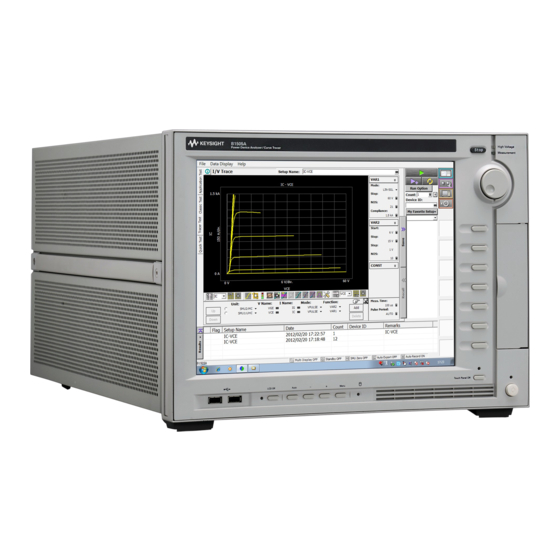
Channel output mode. Set I or IPULSE for the current output and volt- age measurement. Set V or VPULSE for the voltage output and current measurement. Table 1-2 I/V Trace Graph Setup Name Scale Name Scale Y X 1-10 Keysight B1505A User’s Guide, Edition 12... - Page 39 Start Source Stop Compliance 5 mA Step 10 mV Interlacing Compliance 5 mA Pwr Comp. Meas. Time 2 us Dual Polarity Step Time 500 us Figure 1-4 Display Example of I/V Trace Screen Keysight B1505A User’s Guide, Edition 12 1-11...
-
Page 40: To Use Application Test Mode
1-6. 4. Change the measurement conditions at the Test Parameters field. The following example changes the voltage sweep output. a. Set VgStop to 5.0 V. b. Set VdStart and VdStop to 5.0 V. 1-12 Keysight B1505A User’s Guide, Edition 12... - Page 41 You can execute the test without modifications. Also you can create your own test setup/definition by making any changes. All furnished test definitions are just sample. Keysight Technologies is NOT LIABLE for any damages caused by the samples.
-
Page 42: To Use Classic Test Mode
1-6. To enter the value, use the USB keyboard or the screen/numeric keyboard opened by clicking the right button of the entry field. Figure 1-7 Display Example of I/V Sweep Channel Setup Screen 1-14 Keysight B1505A User’s Guide, Edition 12... - Page 43 Step 10 mV No of Step Compliance 5 mA Pwr Comp Sweep CONTINUE AT ANY status Table 1-6 I/V Sweep Display Setup Name Sharing Scale (None) Linear (None) Linear -5 mA 5 mA Keysight B1505A User’s Guide, Edition 12 1-15...
-
Page 44: To Perform Measurement
2. If the automatic data record function has been set to ON (Auto Record ON), Test Result Editor appears on the lower area of the screen when the measurement is completed. See “To Use Test Result Editor” on page 1-17. Figure 1-8 Display Example of Data Display Window 1-16 Keysight B1505A User’s Guide, Edition 12... -
Page 45: To Use Test Result Editor
You can enter characters into this field. The characters will be recorded as the Remarks value of the test result record. • OK button Applies the setup on the Test Result Editor, and closes this dialog box. Keysight B1505A User’s Guide, Edition 12 1-17... -
Page 46: To Use Analysis Tools
Figure 1-8. You can read position of the marker and the active cursor, and interrupt and gradient of the active line. Figure 1-9 Display Example of Analysis Tools 1-18 Keysight B1505A User’s Guide, Edition 12... -
Page 47: Introduction
Introduction... - Page 48 Introduction This chapter describes the basic functions and features of Keysight B1505A Power Device Analyzer/Curve Tracer, and consists of the following sections: • “Overview” • “Front View” • “Rear View” • “Accessories and Options” • “Measurement Resources” NOTE Application Library Keysight B1505A has installed Keysight EasyEXPERT software as the user interface.
-
Page 49: Overview
Windows environment. You can analyze a measurement result characteristics graph for example by using several tools such as markers, cursors, and lines. Also, in the GPIB remote control mode, you can control the B1505A from an external computer by using Keysight FLEX command set that is the common language for Keysight semiconductor DC measurement instruments. - Page 50 Introduction Overview • Keysight B1505A Power Device Analyzer/Curve Tracer Mainframe that provides the ground unit (GNDU) and ten empty slots for the measurement facilities, and Keysight EasyEXPERT software for the operating environment. The EasyEXPERT is the GUI based measurement control and analysis software runs on the Windows.
- Page 51 Selector is initially installed for switching the measurement resource connected to the DUT. The measurement resource will be the UHCU, HP/MPSMU, or HVSMU/HVMCU. The N1254A-524 ultra high current prober system cable is required for extending the selector output to your prober station. Keysight B1505A User’s Guide, Edition 12...
- Page 52 • Keysight N1273A Capacitance Test Fixture Test fixture to enable packaged device capacitance testing (input/output capacitance, feedback capacitance, and gate resistance) in conjunction with the N1272A Device Capacitance Selector. Keysight B1505A User’s Guide, Edition 12...
-
Page 53: Keysight Easyexpert Software
EMF/BMP/GIF/PNG format • Maintenance; self-test and self-calibration • Remote control function from an external computer The EasyEXPERT has the following measurement execution environments. • Application test • Classic test • Tracer test • Quick test Keysight B1505A User’s Guide, Edition 12... - Page 54 • Direct Control The Direct Control test mode is used to control the measurement resources directly by using the B1505A GPIB control commands and perform measurement. For the control commands, see Keysight B1500 Programming Guide. Tracer Test Curve tracer test mode. This test allows you to perform the high speed I-V measurement on one screen.
-
Page 55: Front View
NOTE Before turning the B1505A on Open the measurement terminals at the device side when turning the B1505A on. Also disconnect the device from the measurement terminals and open the measurement terminals after the measurement. If you leave the connection with the device, the device may be damaged by unexpected operations or charge-up of measurement cables. - Page 56 Pressing the knob sets or enters the value. 10. Softkeys Seven softkeys are available for Keysight EasyEXPERT environment. Used to select an alternative for the entry field specified or the dialog box. 2-10 Keysight B1505A User’s Guide, Edition 12...
- Page 57 DVD-ROM drive. 12. Touch Panel Off key Works on the execution environment of EasyEXPERT software. Enables or disables the touch screen operation. The green LED lights when the touch screen is disabled. Keysight B1505A User’s Guide, Edition 12 2-11...
-
Page 58: Rear View
Introduction Rear View Rear View This section describes the rear view of Keysight B1505A. 1. Serial number You need this serial number when using Keysight Technologies telephone assistance program. 2. LED status indicator For troubleshooting. Followings are some examples. •... - Page 59 5. Module slot Ten slots are available for installing the modules. Several kinds of module can be installed in the B1505A. However, the allowable number to install is different by the module type. See “Measurement Resources” on page 2-27.
- Page 60 To verify the interlock function, perform the Interlock Open/Close test on the Main Frame tab screen of the EasyEXPERT Configuration window. 2-14 Keysight B1505A User’s Guide, Edition 12...
- Page 61 VGA connector. For an external display. Signal to the built-in LCD is also applied to this terminal. For the B1505A manufactured before the video output terminal is supported, it is mounted on the position “14a” by upgrading the mainframe. A. GNDU/ADC Ground unit and A/D converter module.
- Page 62 • If the N1268A is used, connect an interlock cable between the B1505A and the N1268A’s Interlock Input, and connect an extra interlock cable between the N1268A’s Interlock Output and the test fixture or the shielding box.
- Page 63 élément, connectez un cordon d'enclenchement à celui utilisé actuellement. • Si le N1268A est utilisé, connectez un câble de verrouillage entre le B1505A et Interlock Input du N1268A, puis connectez un câble de verrouillage supplémentaire entre Interlock Output du N1268A et l'équipement de test ou la boîte de protection.
- Page 64 Ouvrez la trappe d’accès au boîtier de protection (ouvrez la borne Interlock). • Déchargez les éventuels condensateurs si la capacité est connectée à une unité SMU. • Informez les personnes travaillant à proximité de l’instrument des conditions. 2-18 Keysight B1505A User’s Guide, Edition 12...
-
Page 65: Accessories And Options
2/module 16493S HCSMU cable, for the B1505A installed with HCSMU 1/module 16493S-010 HCSMU Kelvin adapter, for the B1505A installed with HCSMU 1/module 16493T HVSMU cable, for the B1505A installed with HVSMU N1300A CMU cable, for the B1505A installed with MFCMU... - Page 66 N1254A-504 HV(jack) to no connector coaxial cable, 1.5 m, 1 ea. N1254A-505 HV(plug) to no connector triaxial cable, 1.5 m, 1 ea. N1254A-506 HV(plug) to no connector coaxial cable, 1.5 m, 1 ea. 2-20 Keysight B1505A User’s Guide, Edition 12...
- Page 67 Thermocouple, Type K, 75 cm, 2 ea. N1254A-556 Test Leads and Connection Kit for Capacitance Test, four 20 cm alligator clip - lug cables, four banana plugs, four nuts, and four spare clips Keysight B1505A User’s Guide, Edition 12 2-21...
- Page 68 Built-in high voltage bias-tee (furnished with two SHV-SHV cables and two SHV-banana adapters) N1259A-021 1 M resistor box N1259A-022 100 k resistor box N1259A N1259A-030 1 k resistor box N1259A-035 Universal resistor box N1259A-300 Built-in module selector N1260A High voltage bias-tee 2-22 Keysight B1505A User’s Guide, Edition 12...
- Page 69 Curve tracer test adapter socket module N1265A-014 Gate charge socket module N1265A-015 Built-in 1500 A ultra high current expander (replaced with built-in 500 A ultra high current expander) N1265A-035 Universal resistor box N1265A-040 Protection adapter for Gate/SMU Keysight B1505A User’s Guide, Edition 12 2-23...
- Page 70 1.5 m length N1300A-002 3 m length 16444A Accessories for B1500 series 16444A-001 USB keyboard 16444A-002 USB mouse 16444A-003 Stylus pen 16493G Digital I/O connection cable 16493G-001 1.5 m length 16493G-002 3 m length 2-24 Keysight B1505A User’s Guide, Edition 12...
- Page 71 16493T-002 3 m length 16493U High current coaxial cable, BNC(m)-BNC(m) 16493U-001 1.5 m length 16493U-002 3 m length 16493V UHVU cable set, UHV(plug)-UHV(plug) and SHV(plug)-SHV(plug) 16493V-001 1.5 m length 16493V-002 3 m length Keysight B1505A User’s Guide, Edition 12 2-25...
- Page 72 Introduction Accessories and Options Model Option Item Description Number 16494A Triaxial cable 16494A-001 1.5 m length 16494A-002 3 m length 16494A-003 80 cm length 16494A-004 40 cm length 16494A-005 4 m length 2-26 Keysight B1505A User’s Guide, Edition 12...
-
Page 73: Measurement Resources
GPIB remote mode. GNDU - Ground Unit The B1505A is equipped with the ground unit (GNDU). The GNDU is a 0 V constant voltage source, and used for the reference of measurement ground. Also the GNDU can sink up to ±4.2 A, so it is effective for using the HPSMU, MPSMU, and HVSMU. -
Page 74: About Smu
When the SMU applies voltage, you can specify current compliance. When the SMU applies current, you can specify voltage compliance. For details about the compliance, see Keysight EasyEXPERT User’s Guide. 2-28 Keysight B1505A User’s Guide, Edition 12... -
Page 75: Hpsmu - High Power Smu
Maximum voltage, current, output power: ± 200 V, ± 1 A, 20 W • Minimum range: 2 V, 1 nA • Output/measurement value and resolution: see Table 2-3 Table 2-6. Figure 2-3 HPSMU Output and Measurement Ranges Current (mA) 1000 Voltage (V) 1000 Keysight B1505A User’s Guide, Edition 12 2-29... - Page 76 50 mA < |I| 125 mA 50 A ± 100 V 125 mA < |I| 500 mA 50 A ± 40 V 500 mA < |I| 1 A 50 A ± 20 V 2-30 Keysight B1505A User’s Guide, Edition 12...
- Page 77 0 |I| 1 A 50 A 1 A a. This column is applied to the auto ranging or the limited auto ranging. For fixed ranging, maximum measurement value is Range column value. Keysight B1505A User’s Guide, Edition 12 2-31...
-
Page 78: Hcsmu - High Current Smu
Putting conductor of circuit common, chassis ground, or any potential on causes the measurement error. Figure 2-4 HCSMU Output and Measurement Ranges by One Module Current (A) Pulse mode only Voltage (V) Pulse mode only 2-32 Keysight B1505A User’s Guide, Edition 12... - Page 79 40 A range and 2 A range The 40 A range and the 2 A range are available when two HCSMU modules are installed in the B1505A and connected to the 16493S-020 Dual HCSMU Kelvin combination adapter or the 16493S-021 Dual HCSMU combination adapter. Two HCSMU modules can be the DHCSMU which supports ±...
-
Page 80: Hvsmu - High Voltage Smu
Multiple B1513A/B1513B HVSMU modules cannot be installed in one mainframe. The B1513A HVSMU cannot be used with the N1267A HVSMU/HCSMU Fast Switch. Figure 2-5 HVSMU Output and Measurement Ranges Current (mA) 3000 1500 Voltage (V) 1500 3000 2-34 Keysight B1505A User’s Guide, Edition 12... - Page 81 0 |I| 1.15 mA 1 nA 3000 V 10 mA 0 |I| 8 mA 10 nA 1500 V 0 |I| 4 mA 3000 V a. DC only Keysight B1505A User’s Guide, Edition 12 2-35...
-
Page 82: Mpsmu - Medium Power Smu
Maximum voltage, current, output power: ± 100 V, ± 100 mA, 2 W • Minimum range: 0.5 V, 1 nA • Output/measurement value and resolution: see Table 2-11 Table 2-14. Figure 2-6 MPSMU Output and Measurement Ranges Current (mA) Voltage (V) 2-36 Keysight B1505A User’s Guide, Edition 12... - Page 83 0 |I| 20 mA 5 A ± 100 V 20 mA < |I| 50 mA 5 A ± 40 V 50 mA < |I| 100 mA 5 A ± 20 V Keysight B1505A User’s Guide, Edition 12 2-37...
- Page 84 0 |I| 100 mA 5 A 100 nA a. This column is applied to the auto ranging or the limited auto ranging. For fixed ranging, maximum measurement value is Range column value. 2-38 Keysight B1505A User’s Guide, Edition 12...
-
Page 85: Mcsmu - Medium Current Smu
• Minimum pulse width: 10 s • Output/measurement value and resolution: see Table 2-15 Table 2-16. Figure 2-7 MCSMU Output and Measurement Ranges Current (A) Pulse mode only Voltage (V) Pulse mode only Keysight B1505A User’s Guide, Edition 12 2-39... - Page 86 0 |I| 115 mA 0 |I| 1 A 1 A ± 50 mA a. For pulse. b. For pulse. Maximum pulse width and duty cycle are 100 ms and 5 % respectively. 2-40 Keysight B1505A User’s Guide, Edition 12...
-
Page 87: Hvmcu - High Voltage Medium Current Unit
SMU. Connecting other measurement resource may damage the connected one. Figure 2-8 HVMCU Output and Measurement Ranges Current (A) 2200 1500 0.11 Voltage (V) 0.11 1500 2200 Keysight B1505A User’s Guide, Edition 12 2-41... - Page 88 0 |I| 0.11 A 200 nA ± 2200 V 0 |I| 1.1 A 4 A ± 2200 V 0 |I| 2.5 A 4 A ± 1500 V 2-42 Keysight B1505A User’s Guide, Edition 12...
-
Page 89: Uhcu - Ultra High Current Unit
Maximum pulse duty: 0.4 % for 500 A range, or 0.1 % for 2000 A range • Output/measurement value and resolution: see Table 2-19 Table 2-20. Figure 2-9 UHCU Output and Measurement Ranges Current (A) 1500 Voltage (V) 1500 Keysight B1505A User’s Guide, Edition 12 2-43... - Page 90 4 mA 2 mA 2000 A a. Pulse base value is always 0 A. b. This is the maximum voltage compliance value. c. Only for the N1265A-015. Pulse base value is always 0 A. 2-44 Keysight B1505A User’s Guide, Edition 12...
-
Page 91: Uhvu - Ultra High Voltage Unit
Minimum pulse period: 10 ms • Output/measurement value and resolution: see Table 2-21 Table 2-22. Figure 2-10 UHVU Output and Measurement Ranges Current (mA) 10000 Voltage (V) 10000 *1: Pulse width must be 1 ms or less. Keysight B1505A User’s Guide, Edition 12 2-45... - Page 92 CAUTION Never connect the UHVU Low terminal to any other measurement resource except for the N1269A or N1265A-040 adapter. Connecting other measurement resource may damage the connected one. 2-46 Keysight B1505A User’s Guide, Edition 12...
-
Page 93: Mfcmu - Multi Frequency Cmu
Use these information to decide the measurement range. Impedance Z is calculated by the following formula. Z = 1 / (2 f C) where f is frequency (Hz) and C is capacitance (F). Keysight B1505A User’s Guide, Edition 12 2-47... - Page 94 Q (quality factor) Lp (parallel inductance, H) Rp (parallel resistance, ) Ls (series inductance, H) Rs (series resistance, ) Ls (series inductance, H) D (dissipation factor) Ls (series inductance, H) Q (quality factor) 2-48 Keysight B1505A User’s Guide, Edition 12...
- Page 95 100 nF 100 m 10 m 10 F 100 F 1 mF 10 mF range 100 mF 100 n 10 n 1 kHz 10 kHz 100 kHz 1 MHz 5 MHz Frequency f Keysight B1505A User’s Guide, Edition 12 2-49...
- Page 96 Introduction Measurement Resources 2-50 Keysight B1505A User’s Guide, Edition 12...
-
Page 97: Accessories
Accessories... - Page 98 Accessories This chapter explains the following accessories available for Keysight B1505A. • “N1258A Module Selector” • “N1259A Test Fixture” • “N1260A High Voltage Bias-Tee” • “N1261A Protection Adapter” • “N1262A Resistor Box” • “16493S-010/011 HCSMU Adapter” • “16493S-020/021 Dual HCSMU Adapter”...
- Page 99 The B1505A, the N1265A ultra high current expander/fixture, and the N1268A ultra high voltage expander are heavy and require a two person lift. Le B1505A, le N1265A ultra high current expander/fixture et le N1268A ultra high voltage expander sont lourds et nécessitent deux personnes pour les soulever.
-
Page 100: N1258A Module Selector
BNC(m) connector for Force, normal cable with BNC(m) connector for Sense, manipulators, and such. b. High Force and Sense output connectors HV(jack) connectors. Force and Sense must be extended to and connected together at a high terminal of the DUT. Keysight B1505A User’s Guide, Edition 12... - Page 101 HCSMU Low Sense HCSMU Low Force Open Open + GNDU Force HPSMU HPSMU Sense HPSMU Force + GNDU Sense HCSMU HCSMU High Sense HCSMU High Force HVSMU HVSMU Force Open HVSMU Force + Series resistor Keysight B1505A User’s Guide, Edition 12...
- Page 102 Do not put any conductor on the HCSMU Low Force and Low Sense terminals, outer conductor of the coaxial connectors. Putting conductor of circuit common, chassis ground, or any potential on causes the measurement error. Keysight B1505A User’s Guide, Edition 12...
- Page 103 Normally, connect the terminals together by using the shorting bar. Removing the shorting bar may be effective for reducing external noise caused by the ground loop. Then do not break the connection between the B1505A’s Circuit Common and the prober station’s frame ground.
- Page 104 For floating measurement, do not apply dangerous voltage to the Circuit Common terminal. Failure to heed this caution may result in damage to the N1258A. NOTE Module selector may emit a noise sound during operation. However it is not abnormal status. Keysight B1505A User’s Guide, Edition 12...
-
Page 105: N1259A Test Fixture
3. Hazardous voltage status indicator This red LED lights when a source channel applies dangerous voltage. This indicator is connected to the B1505A via the Interlock connector and works with the High Voltage indicator on the B1505A’s front panel. Keysight B1505A User’s Guide, Edition 12... - Page 106 Assurez-vous que le couvercle est fermé correctement avant de commencer la mesure. Ne pas effectuer la mesure lorsqu’un câble dépasse du couvercle de l'appareil. 3-10 Keysight B1505A User’s Guide, Edition 12...
- Page 107 HV(jack) connector. For connecting 16493T HVSMU cable from the HVSMU or the HVMCU High. • GNDU1 input connector GNDU triaxial connector. For connecting 16493L GNDU cable from the GNDU or the HVMCU Low. Keysight B1505A User’s Guide, Edition 12 3-11...
- Page 108 Putting conductor of circuit common, chassis ground, or any potential on causes the measurement error. 5. Digital I/O connector (N1259A-300) For connecting 16493G cable from the Digital I/O connector of B1505A or N1266A expander. 6. LINE input receptacle (N1259A-300) AC power cable is connected to this receptacle.
- Page 109 Accessories 7. Serial number You need this serial number when using Keysight Technologies telephone assistance program. Table 3-2 N1259A Status Indicator and Module Selector Connection Path Module Selector Output terminals Status indicator Low Sense Low Force High Sense High Force...
- Page 110 Press the B1505A front panel key to set the output off. And confirm that Stop the B1505A front panel High Voltage indicator is not lit. Désactivez la sortie de l'appareil avant de brancher ou de débrancher un câble de connexion.
- Page 111 Output terminals internally connected to the AUX1 and AUX2 input connectors. Signal and frame ground terminals for each AUX. Signal must be connected to a terminal of a DUT. Frame ground may be connected to the ground terminal of the DUT. Keysight B1505A User’s Guide, Edition 12 3-15...
- Page 112 Press the B1505A front panel key to set the output off. And confirm that Stop the B1505A front panel High Voltage indicator is not lit. Désactivez la sortie de l'appareil avant de brancher ou de débrancher un câble de connexion.
- Page 113 Module selector may emit a noise sound during operation. However it is not abnormal status. 2. Resistor box For reducing damage of DUT or preventing SMU from oscillation. The following resistors are available by the options. Keysight B1505A User’s Guide, Edition 12 3-17...
- Page 114 Connect wires (N1254A-508 or 509) between the socket module terminals and the fixture output terminals. For making the Kelvin connection, Force and Sense must be connected to Force and Sense of the socket module respectively. 3-18 Keysight B1505A User’s Guide, Edition 12...
- Page 115 Package Socket Module. To use this module, see the following simple instruction. For the component locations and dimensions, see Figure 3-4. Also see “Inline Package Socket Module (N1259A-010)” on page 3-18 to perform measurement. Keysight B1505A User’s Guide, Edition 12 3-19...
- Page 116 Laissez suffisamment d'espace entre la prise/la borne MST et la protection/le châssis. Par exemple, environ 1 mm pour une sortie de 200 V au maximum et 6 mm pour 3 000 V afin d'éviter toute décharge et tout accident. g. Reattach the cover. 3-20 Keysight B1505A User’s Guide, Edition 12...
- Page 117 Low Sense, GNDU Force, and GNDU Sense must be connected to the low terminal of the DUT. e. Make sure the DUT location. The DUT must be placed on the blank PTFE board properly. Keysight B1505A User’s Guide, Edition 12 3-21...
- Page 118 Sense must be connected to Sense used for the low terminal of the DUT. d. Set the DUT on your test adapter. e. Close the fixture cover and perform measurement. CAUTION Do not apply voltage/current over the maximum limit of the socket module. 3-22 Keysight B1505A User’s Guide, Edition 12...
- Page 119 DUT. If the device is not available, use a load resistor. The resistor must satisfy the following specifications. Resistance = Vr/Ir (Vr: rated voltage, Ir: rated current) Keysight B1505A User’s Guide, Edition 12 3-23...
- Page 120 High: Max. 30 V / 1A floating 3000 V Low: Max. 10 V / 1A floating 3000 V Curve Tracer Test Adapter Socket Figure 3-8 Connection Example for High Voltage Gate Charge Measurement 3-24 Keysight B1505A User’s Guide, Edition 12...
- Page 121 High terminal on the fixture to the Selector Output Force High terminal on the N1259A-014 adapter. Measurement may fail depending on the device characteristics if it is connected to the Selector Output Sense High terminal. Keysight B1505A User’s Guide, Edition 12 3-25...
-
Page 122: N1260A High Voltage Bias-Tee
Never connect the HVSMU Force and Guard terminals to any output, including circuit common, chassis ground, or any other measurement resource such as SMU. Connecting other measurement resource may damage the connected one. 3-26 Keysight B1505A User’s Guide, Edition 12... -
Page 123: N1261A Protection Adapter
Kelvin connection effective for low resistance and high current measurements. • From GNDU of N1261A-002 and 004 GNDU triaxial connector. For connecting 16493L GNDU cable from the GNDU. Keysight B1505A User’s Guide, Edition 12 3-27... -
Page 124: N1262A Resistor Box
HVMCU, UHVU, or UHCU, the SMU may cause oscillation. Then this adapter should be connected between the gate drive output and a DUT terminal. This will be effective for preventing oscillation. 3-28 Keysight B1505A User’s Guide, Edition 12... - Page 125 Triaxial(m) connector, manipulators, and such. • Output of N1262A-023 UHV(jack) connector. Signal must be extended to a terminal of a DUT. For making the connection, use ultra high voltage cable with UHV(plug) connector, manipulators, and such. Keysight B1505A User’s Guide, Edition 12 3-29...
-
Page 126: 16493S-010/011 Hcsmu Adapter
Do not put any conductor on the HCSMU Low Force and Low Sense terminals, outer conductor of the coaxial connectors. Putting conductor of circuit common, chassis ground, or any potential on causes the measurement error. 3-30 Keysight B1505A User’s Guide, Edition 12... -
Page 127: 16493S-020/021 Dual Hcsmu Adapter
Adapters for Dual HCSMU operation. The adapters are used to connect two HCSMU modules installed in one B1505A. Using two modules can expand the B1505A maximum current up to ± 40 A (pulse), ± 2 A (DC). 16493S-020: Dual HCSMU Kelvin combination adapter This adapter is used with a DUT interface such as your own test fixture and prober station, not the N1259A/N1265A test fixture. - Page 128 Do not put any conductor on the HCSMU Low Force and Low Sense terminals, outer conductor of the coaxial connectors. Putting conductor of circuit common, chassis ground, or any potential on causes the measurement error. 3-32 Keysight B1505A User’s Guide, Edition 12...
-
Page 129: N1265A Ultra High Current Expander/Fixture
N1265A UHC expander/fixture Digital I/O Digital I/O Interlock Interlock High Drain GNDU GNDU HVSMU HVSMU HP/MPSMU Source UHCU MC/HCSMU I-control MC/HCSMU V-control NOTE For the gate terminal of DUT, use MCSMU or HCSMU. Keysight B1505A User’s Guide, Edition 12 3-33... - Page 130 4. Hazardous voltage status indicator This red LED lights when a measurement resource applies dangerous voltage. This indicator is connected to the B1505A via the Interlock connector and works with the High Voltage indicator on the B1505A’s front panel. Warming labels written in French, German, and Japanese are furnished. Attach the label to the front panel of the fixture if you need.
- Page 131 I Control Force Force Force Force 100- 240 V 50/60 Hz 400 VA Max GNDU N10149 Sense Sense Sense Sense KCC-REM-ATi- 1H-ParaINSTR ±3 kV Max ±200 V Max ±40 V Max ±40 V Max Keysight B1505A User’s Guide, Edition 12 3-35...
- Page 132 To connect HCSMU, use 16493S HCSMU cable, N1254A-103 adapter for Force, and N1254A-517 adapter for Sense. To connect DHCSMU, use 16493S-021 adapter, 16493S HCSMU cables, N1254A-103 adapter for Force, and N1254A-517 adapter for Sense. 3-36 Keysight B1505A User’s Guide, Edition 12...
- Page 133 Accessories 2. Serial number label You need this serial number when using Keysight Technologies telephone assistance program. 3. Option number label 4. Interlock connector Interlock connector. For connecting 16493J interlock cable from B1505A. WARNING Potentially hazardous voltage may be present at the High, Force, Sense, and Guard terminals when the interlock terminals are shorted on test fixture, prober station, and such.
- Page 134 HVMCU Low. 11. LINE input receptacle and power switch AC power cable is connected to this receptacle. Power switch turns on/off the N1265A. Paths other than the Selector Output do not need AC power. 3-38 Keysight B1505A User’s Guide, Edition 12...
- Page 135 Press the B1505A front panel key to set the module output off. And confirm Stop that the B1505A front panel High Voltage indicator is not lit. If the N1268A is used, press the switch to disable the high High Voltage Enable voltage output.
- Page 136 The adapter is required to protect MCSMU from ultra high voltage. 2. Gate High and Low terminals Output terminals internally connected to the Gate input connectors on the rear panel. High and Low terminals used for the gate drive. 3-40 Keysight B1505A User’s Guide, Edition 12...
- Page 137 High and Low must be connected to the high and low terminals of a DUT respectively. Use SHV(plug)-SHV(plug) cable (N1254A-512) and SHV(jack)-banana adapter (N1254A-513) for connection. CAUTION Open the Bias Tee terminals for the ultra high voltage measurement using UHVU. Keysight B1505A User’s Guide, Edition 12 3-41...
- Page 138 F: Force S: Sense 0 Ω P.A: Protection adapter 10 Ω 100 Ω or 1 kΩ 100 kΩ HVSMU force is connected to UHCU High sense line. V-control I-control MCSMU GNDU MCSMU MCSMU HVSMU 3-42 Keysight B1505A User’s Guide, Edition 12...
- Page 139 And connect all three Low terminals to the source/emitter terminal. For the other cases, never connect any other measurement resource to the UHVU Low terminal or the DUT terminal connected to it. Connecting other measurement resource may damage the connected one. Keysight B1505A User’s Guide, Edition 12 3-43...
- Page 140 Press the B1505A front panel key to set the module output off. And confirm Stop that the B1505A front panel High Voltage indicator is not lit. If the N1268A is used, press the switch to disable the high High Voltage Enable voltage output.
- Page 141 For the high voltage capacitance measurement, use SHV(plug)-SHV(plug) cable (N1254A-512) and SHV(jack)-banana adapter (N1254A-513) for connection. Selector Output and Gate should be connected as follows. • Selector Output High to DUT high (ex. Collector/Drain) Keysight B1505A User’s Guide, Edition 12 3-45...
- Page 142 3-S: 40 A pulse, 2 A dc F: Force Inline Package Socket (3 Pin) S: Sense 14 mm Height: 34 mm 3.48 mm (45 mm including terminal) (58 mm including socket) 1.78 mm 3-46 Keysight B1505A User’s Guide, Edition 12...
- Page 143 4. Fix the board to the blank module. 5. Remove the cover bottom of the blank module. 6. Mount the socket or DUT on the board and solder wire between its terminals and the blank module terminals. Keysight B1505A User’s Guide, Edition 12 3-47...
- Page 144 3. Connect wires between the socket module terminals and the fixture output terminals. Then use the following wire. • N1254A-522 wire (yellow) for Selector Output High/Low Force • N1254A-508 or 509 wire for Selector Output High/Low Sense, Gate, SMU, or chassis 3-48 Keysight B1505A User’s Guide, Edition 12...
- Page 145 You can use the following wires supplied with the socket module. • N1254A-522: high current wire (yellow), 2 ea. • N1254A-508: long wire (red), 2 ea. • N1254A-509: long wire (black), 2 ea. • N1265-61751: short wire (red), 2 ea. Keysight B1505A User’s Guide, Edition 12 3-49...
- Page 146 Low: Max. 10 V / 20 mA SMU Current Control High: Max. 30 V / 1A floating 3000 V Low: Max. 10 V / 1A floating 3000 V Curve Tracer Test Adapter Socket 3-50 Keysight B1505A User’s Guide, Edition 12...
- Page 147 Accessories Figure 3-16 Connection Example for High Current Gate Charge Measurement Figure 3-17 Connection Example for High Voltage Gate Charge Measurement Keysight B1505A User’s Guide, Edition 12 3-51...
- Page 148 The GNDU signals will appear at the Selector Output Low terminals as shown in Table 3-5. 4. Make sure the DUT location. The DUT must be placed on the blank silicon plate properly. 3-52 Keysight B1505A User’s Guide, Edition 12...
- Page 149 This container can accommodate protection adapters and bias-tee which are used with the N1265A to make the measurement environment clean and safe. Maximum superimposed load is 50 kg. The N1265A and the N1266A can be put on the top of the container. Keysight B1505A User’s Guide, Edition 12 3-53...
- Page 150 Ne jamais connecter le câble de verrouillage au N1265A. Ne jamais ôter les plaques en plastique transparent du couvercle d'appareil du N1265A. CAUTION Do not apply voltage/current over the maximum limit of the cable. 3-54 Keysight B1505A User’s Guide, Edition 12...
-
Page 151: N1266A Hvsmu Current Expander
Input-to-output connection of output terminals Status indicator High (off) GNDU Force and Sense Open HVMCU HVMCU High HVSMU HVSMU Force HVSMU Force + Series resistor NOTE For the gate terminal of DUT, use MCSMU or HCSMU. Keysight B1505A User’s Guide, Edition 12 3-55... - Page 152 Input V Control Force and Sense Triaxial connectors. For connecting 16494A triaxial cables from Force and Sense connectors of the MCSMU. HCSMU is substitutable. Then use 16493S HCSMU cable, N1254A-103 adapter for Force, and N1254A-517 adapter for Sense. 3-56 Keysight B1505A User’s Guide, Edition 12...
- Page 153 For connecting 16493G cable to the Digital I/O connector of N1268A expander, module selector, or any accessory. • Digital I/O connector Input For connecting 16493G cable from the Digital I/O connector of B1505A or N1265A fixture. • LINE input receptacle and power switch AC power cable is connected to this receptacle.
-
Page 154: N1267A Hvsmu/Hcsmu Fast Switch
Never connect the output High Force and Guard terminals to any output, including circuit common, chassis ground, or any other measurement resource such as SMU. Connecting other measurement resource may damage the connected one. 3-58 Keysight B1505A User’s Guide, Edition 12... - Page 155 GNDU must be connected to the device under test (DUT) without passing through the N1267A. If the DUT is a diode, ignore MCSMU for Gate in Figure 3-21. The B1505A provides the following tracer test setup using the N1267A. • GaN FET (N1267A): •...
- Page 156 Accessories The B1505A also provides the following application test definitions. • GaN FET: • FET current collapse measurement, IV-t sampling • FET current collapse measurement, signal monitor • GaN Diode: • Diode current collapse measurement, IV-t sampling • Diode current collapse measurement, signal monitor...
- Page 157 1500 V 1 V to 1500 V 1.5 mV 3000 V 1 V to 3000 V 3 mV 4 mA a. Setting value must be the ON state voltage plus 1 V or more. Keysight B1505A User’s Guide, Edition 12 3-61...
- Page 158 HVSMU Resolution Range Resolution Range 100 mA 100 nA 10 mA 10 nA 1 A 20 A (pulse) 20 A a. Range depends on the HCSMU source setting for the device ON state. 3-62 Keysight B1505A User’s Guide, Edition 12...
- Page 159 100 A 100 pA 1 mA 1 nA 10 mA 10 nA 100 mA 100 nA 1 A 20 A (pulse) 20 A Offset error for the Id-Vds, If-Vf measurement is typical 1 A. Keysight B1505A User’s Guide, Edition 12 3-63...
- Page 160 100 pA 100 A 100 pA 1 mA 1 nA 1 mA 1 nA 10 mA 10 nA 10 mA 10 nA Leak error for the Id(Off)-Vds, Ir-Vr measurement is typical 2 nA. 3-64 Keysight B1505A User’s Guide, Edition 12...
- Page 161 HVSMU. After the N1267A switch status is changed from OFF to ON, HVSMU current is limited by the internal circuit, and voltage goes down. Finally it causes the current shift of Current limit change after Current limit period elapsed. Keysight B1505A User’s Guide, Edition 12 3-65...
- Page 162 1.3 + 0.043 I 3 A < |I | 20 A 1.1 + 0.062 I 3 A < |I | 20 A a. I : HCSMU output current (A) 3-66 Keysight B1505A User’s Guide, Edition 12...
-
Page 163: N1268A Ultra High Voltage Expander
± 42 V. • Earth terminal Screw terminal for earthing. • LINE input receptacle AC power cable is connected to this receptacle. • POWER indicator This green LED lights when the N1268A is turned on. Keysight B1505A User’s Guide, Edition 12 3-67... - Page 164 • Interlock Input and Output Interlock connector. Input connector is for connecting 16493J interlock cable from B1505A. And Output connector is for connecting 16493J interlock cable from test fixture, prober station, and such. WARNING Potentially hazardous voltage may be present at the High terminal when the interlock terminals are shorted on test fixture, prober station, and such.
- Page 165 N1268A UHV expander MCSMU I-control Drain MC/HCSMU V-control High Digital I/O Digital I/O Interlock Interlock Input Source Interlock Output Interlock circuit NOTE For the gate terminal of DUT, use MCSMU. Another module cannot be used. Keysight B1505A User’s Guide, Edition 12 3-69...
-
Page 166: N1269A Ultra High Voltage Connection Adapter
Triaxial connectors. For connecting 16494A triaxial cables from Force and Sense connectors of the MCSMU. HCSMU is NOT substitutable. • Gate, Source, Chuck SHV(jack) connectors. To connect prober, use cables with SHV(plug) connector, manipulators, and such. 3-70 Keysight B1505A User’s Guide, Edition 12... -
Page 167: N1271A Thermal Test Enclosure
Four 30 cm small alligator clip - lug cables, four banana plugs, four nuts, and four spare clips • Two 30 cm large alligator clip - lug cables, two banana plugs, and two nuts Keysight B1505A User’s Guide, Edition 12 3-71... - Page 168 8. (for N1265A) If you use the thermocouple, do the following. a. Connect the thermocouple to the K Thermocouple terminal. b. Secure the end of the thermocouple to the place for monitoring temperature. 3-72 Keysight B1505A User’s Guide, Edition 12...
- Page 169 The enclosure cover on the top surface is the docking interface with the Thermostream. • Test leads and connection kit for thermal test (N1254A-557) • Six 20 cm small alligator clip - lug cables, six banana plugs, six nuts, and six spare clips Keysight B1505A User’s Guide, Edition 12 3-73...
- Page 170 Ne rien placer d’autre que ce qui est spécifié sur le piédestal. 3. If you use the thermocouple, connect the thermocouple to the K Thermocouple terminal. 4. Face the terminals on the adapter rear panel to the fixture output terminals, and 3-74 Keysight B1505A User’s Guide, Edition 12...
- Page 171 12. Set the left side wire head in the slit of the test fixture interlock switch and ram it down. 13. Set the right side wire head in the slit of the test fixture interlock switch and ram it down. 14. Leave the fixture cover open and perform measurement. Keysight B1505A User’s Guide, Edition 12 3-75...
- Page 172 WARNING Purge air inlet To prevent condensation, connect the Thermostream purge air tube here. Purgez l'admission d'air Pour empêcher toute formation de condensation, connectez le tube de purge d'air Thermostream ici. 3-76 Keysight B1505A User’s Guide, Edition 12...
- Page 173 SMU [1] connector: HPSMU Force • SMU [2] connector: HPSMU Sense • SMU [3] connector: MPSMU Force • SMU [4] connector: MPSMU Sense • SMU [5] connector: MCSMU Force • SMU [6] connector: MCSMU Sense Keysight B1505A User’s Guide, Edition 12 3-77...
- Page 174 Four 30 cm small alligator clip - lug cables, four banana plugs, four nuts, and four spare clips • Two 30 cm large alligator clip - lug cables, two banana plugs, and two nuts 3-78 Keysight B1505A User’s Guide, Edition 12...
- Page 175 4. Put the enclosure on the pedestal and connect the following cables to the associated terminals on the fixture properly. • Bias Tee High cable • Bias Tee Low cable • UHV High cable Keysight B1505A User’s Guide, Edition 12 3-79...
- Page 176 13. Set the left side wire head in the slit of the test fixture interlock switch and ram it down. 14. Set the right side wire head in the slit of the test fixture interlock switch and ram it down. 15. Leave the fixture cover open and perform measurement. 3-80 Keysight B1505A User’s Guide, Edition 12...
- Page 177 SMU. SMU 1 input on the N1265A rear panel must be connected to a MCSMU as shown below. • SMU [1] connector: MCSMU Force • SMU [2] connector: MCSMU Sense Keysight B1505A User’s Guide, Edition 12 3-81...
- Page 178 SMU [1] connector: MCSMU Force • SMU [2] connector: MCSMU Sense • SMU [3] connector: HPSMU Force • SMU [4] connector: HPSMU Sense • SMU [5] connector: MPSMU Force • SMU [6] connector: MPSMU Sense 3-82 Keysight B1505A User’s Guide, Edition 12...
-
Page 179: N1272A Device Capacitance Selector
Selector input-to-output internal connection is controlled by the application test automatically. Also, it can be controlled directly by using the Direct Control classic test. See Keysight B1500 Programming Guide for the control commands. Keysight B1505A User’s Guide, Edition 12 3-83... - Page 180 1. Digital I/O connectors Input connector: For connecting the furnished Digital I/O cable (B1506-61780) from the Digital I/O connector of B1505A. If the selector is used with other fixture or selector, you can also connect the output from it to this input connector.
- Page 181 Interlock connector. For connecting the 16493J interlock cable from B1505A. For the measurement using the N1259A/N1265A fixture, open this terminal. The B1505A Interlock must be connected to the used one. 3. Output a. Collector/Drain output connector SHV(jack) connector. If the N1273A fixture is used, connect the composite cable (B1507-61720) from the Collector/Drain input connector of the N1273A.
- Page 182 NOTE To prevent the occurrence of forgetting to turn on the selector, it is recommended to turn the selector on before turning on the B1505A mainframe. NOTE The selector may emit a noise sound during operation. However, this is not an abnormal status.
-
Page 183: N1273A Capacitance Test Fixture
Pour des raisons de sécurité, vérifier la fonction de verrouillage après le changement de connexion. Pour vérifier la fonction de verrouillage, effectuer l'Interlock Open/Close test sur l'écran de l'onglet Main Frame de la fenêtre EasyEXPERT Configuration. Front Panel Keysight B1505A User’s Guide, Edition 12 3-87... - Page 184 1. Hazardous voltage status indicator This red LED lights when a source channel applies dangerous voltage. This indicator is connected to the B1505A via the Interlock connector and works with the High Voltage indicator on the B1505A’s front panel. Warning labels written in French, German, and Japanese are furnished. Attach the label to the front panel of the fixture if you need.
- Page 185 N1273A. • Base/Gate input connector SHV(jack) connector. For connecting the composite cable (B1507-61720) from the Base/Gate output connector of the N1272A selector. The composite cable is supplied with the N1273A. Keysight B1505A User’s Guide, Edition 12 3-89...
- Page 186 Press the B1505A front panel key to set the module output off. And confirm Stop that the B1505A front panel High Voltage indicator is not lit. Désactivez la sortie de l'appareil avant de brancher ou de débrancher un câble de connexion.
- Page 187 Utilisez des gants et des outils. Prévoyez également du temps pour la décharge et la radiation. WARNING Hazardous voltage, instrument maximum output voltage may appear at the measurement terminals if the fixture cover is closed. Keysight B1505A User’s Guide, Edition 12 3-91...
- Page 188 4. Set your DUT on the socket. 5. Close the fixture cover and perform measurement. CAUTION Do not apply voltage/current over the maximum limit of the socket module. Terminal rated voltage: 3000 Vdc Terminal rated current: 120 mA 3-92 Keysight B1505A User’s Guide, Edition 12...
- Page 189 (14 ea.) supplied with the socket module • socket, if you use, and packaged device under test (DUT) • T-10 and T-15 Torx screwdrivers • 9 mm wrench • caulking tool for lug terminals, 2.0sq Keysight B1505A User’s Guide, Edition 12 3-93...
- Page 190 6. Assemble cables using the wire and lug terminals. Cut the appropriate length of the wire, tear off the coating of wire ends, and then secure the lug terminals to the wire ends using a caulking tool. 3-94 Keysight B1505A User’s Guide, Edition 12...
- Page 191 9. Fix the bottom cover to the blank module using a T10 Torx screwdriver. CAUTION Do not apply voltage/current over the maximum limit of the socket module. Terminal rated voltage: 3000 Vdc Terminal rated current: 120 mA Keysight B1505A User’s Guide, Edition 12 3-95...
- Page 192 3. Set the DUT on your test adapter. 4. Close the fixture cover and perform measurement. CAUTION Do not apply voltage/current over the maximum limit of the socket module. Terminal related voltage: 3000 Vdc Terminal related current: 100 mA 3-96 Keysight B1505A User’s Guide, Edition 12...
- Page 193 Press the B1505A front panel key to set the module output off. And Stop confirm that the B1505A front panel High Voltage indicator is not lit. Désactivez la sortie de l'appareil avant de brancher ou de débrancher un câble de connexion.
- Page 194 Assurez-vous que le couvercle est fermé correctement avant de commencer la mesure. Ne pas effectuer la mesure lorsqu’un câble dépasse du couvercle de l'appareil. 3-98 Keysight B1505A User’s Guide, Edition 12...
-
Page 195: N1274A On-Wafer Gate Charge Measurement Adapter/Selector For
Low Force and Sense input connectors BNC connectors. For connecting two BNC cables (B1512-61741) from the Low Force and Sense connectors of the N1258A. These BNC cables are supplied with the N1274A. Keysight B1505A User’s Guide, Edition 12 3-99... - Page 196 BNC connector. This must be extended to the Base/Gate terminal of a DUT. For making the connection, use a cable with BNC(m) connector, manipulators, and such. This is connected to the High force/sense terminals of MCSMU/HCSMU connected for driving the DUT. 3-100 Keysight B1505A User’s Guide, Edition 12...
- Page 197 DUT Gate Control MCSMU/HCSMU Force and Sense input connectors Force and Sense triaxial connectors. For connecting the 16494A triaxial cable from an MCSMU in the B1505A mainframe. Or, for connecting the 16493S HCSMU cable from an HCSMU in the B1505A mainframe.
- Page 198 DUT Gate Control MCSMU/HCSMU Sense Output 3000 V 20 A High Force 3000 V 20 mA High Sense 10 V 20 A Low Force 10 V 20 mA Low Sense 30 V Gate 3-102 Keysight B1505A User’s Guide, Edition 12...
-
Page 199: N1275A On-Wafer Gate Charge Measurement Adapter For N1265A
(N1275-61701) is supplied with the N1275A. b. To DUT output connector Banana(jack) connector. This must be extended to the Collector/Drain terminal of a DUT. For making the connection, use a cable with banana(plug) connector, manipulators, and such. Keysight B1505A User’s Guide, Edition 12 3-103... - Page 200 • Current Control MCSMU Force and Sense input connectors Force and Sense triaxial connectors. For connecting 16494A triaxial cable from an MCSMU in the B1505A mainframe. This is used to drive a current control device. Figure 3-34 On-Wafer Gate Charge Measurement Adapter To perform the gate charge measurement, a current control device or a load resistor must be mounted on the socket or the studs.
-
Page 201: Installation
Installation... - Page 202 The B1505A, the N1265A ultra high current expander/fixture, and the N1268A ultra high voltage expander are heavy and require a two person lift. Le B1505A, le N1265A ultra high current expander/fixture et le N1268A ultra high voltage expander sont lourds et nécessitent deux personnes pour les soulever.
- Page 203 • If the N1268A is used, connect an interlock cable between the B1505A and the N1268A’s Interlock Input, and connect an extra interlock cable between the N1268A’s Interlock Output and the test fixture or the shielding box.
- Page 204 élément, connectez un cordon d'enclenchement à celui utilisé actuellement. • Si le N1268A est utilisé, connectez un câble de verrouillage entre le B1505A et Interlock Input du N1268A, puis connectez un câble de verrouillage supplémentaire entre Interlock Output du N1268A et l'équipement de test ou la boîte de protection.
-
Page 205: Requirements
Humidity: 10 % to 90 % RH, non-condensing 20 % to 80 % RH, non-condensing, for using N1268A Altitude: 0 to 4,600 m (15,092 ft.) 0 to 2,000 m (6,561 ft.), for using N1268A Keysight B1505A User’s Guide, Edition 12... -
Page 206: Installation Requirements
Make sure that there is enough space for connecting/disconnecting the power cable easily. Do not put anything on the N1268A Ultra High Voltage Expander. WARNING Ne rien placer sur le N1268A Ultra High Voltage Expander. Keysight B1505A User’s Guide, Edition 12... -
Page 207: Power Cable
Keysight Sales and Support Office. The AC input on the back of your instrument is a universal AC input. It accepts nominal line voltages in the range of 100 to 240 VAC. Keysight B1505A User’s Guide, Edition 12... - Page 208 PN: 8120-0674 • PN: 8120-8376 • PN: 8121-0564 Option 931 Option 932 • Plug: CNS 10917-2, • Plug: CS 0017, 125 V, 10 A 250 V, 10 A • PN: 8121-1635 • PN: 8121-1638 Keysight B1505A User’s Guide, Edition 12...
-
Page 209: Inspection And Installation
• water marks If you suspect any damage, notify your local Keysight Technologies sales or service office. 2. When you open the boxes that contain the instrument and accessories, check the components against the contents lists attached to the boxes. -
Page 210: To Perform Initial Setup
If the instrument has been already connected to your site LAN, you can proceed the network connection setup. NOTE Other Windows setup You can set other setup of Windows after the initial setup. It is your responsibility. 4-10 Keysight B1505A User’s Guide, Edition 12... -
Page 211: To Change Windows Logon Setting
You can add users after the initial setup. Add users as you need. To Change Windows Logon Setting Keysight B1505A initially enables Windows automatic logon. If you want to change this setting, select All Programs > Control Auto Logon from the Start menu. Control Auto Logon is displayed on the browser. -
Page 212: To Change Gpib Address
The USB/GPIB interface might cause serial poll error intermittently due to the intrinsic communication scheme differences. It is reported that using an even GPIB address sometimes significantly decreases the chance of the error. 4-12 Keysight B1505A User’s Guide, Edition 12... -
Page 213: To Enable System Controller
NOTE To Disable System Controller If the B1505A is the system controller, you cannot control the B1505A by using an external computer. To disable the system controller, change the steps 4 and 5 for setting the GPIB Address value to not 21 and removing the check from the System Controller box, and perform the procedure to the step 8. -
Page 214: Maintenance
• Self-calibration • Diagnosis If problems arise, contact Keysight Technologies. For details, see Keysight EasyEXPERT User’s Guide. NOTE Before performing the diagnosis of N1265A UHC Expander / Fixture When the diagnosis of the N1265A is performed, the N1266A HVSMU Current Expander must not be connected to the N1265A. -
Page 215: Calibration
Interlock function limits the maximum output voltage to ± 42 V when the measurement terminal is touchable. For safety, this function must be checked before using the B1505A after power on at least once a day by performing the diagnosis. -
Page 216: About Plug-In Modules
For example, if the module configuration is two HPSMU, one MFCMU, one HCSMU, and one HVSMU, the B1505A will be shipped with the HPSMU of the slots 1 to 4, the MFCMU of the slot 5, the HCSMU of the slots 6 to 7, the HVSMU of the slots 8 to 9, and the blank panel of the slot 10. - Page 217 B1513A/B/C High Voltage SMU (HVSMU) B1512A High Current SMU (HCSMU) B1514A Medium Current SMU (MCSMU) B1520A Multi Frequency CMU (MFCMU) B1511A/B Medium Power SMU (MPSMU) B1510A High Power SMU (HPSMU) bottom GNDU/ADC (always installed) Keysight B1505A User’s Guide, Edition 12 4-17...
- Page 218 Installation About Plug-in Modules 4-18 Keysight B1505A User’s Guide, Edition 12...
-
Page 219: Measurement Examples
Measurement Examples... - Page 220 Measurement Examples This chapter introduces some measurement examples using Keysight B1505A. • “Gate Charge Measurement” • “I-V and Capacitance Measurements Using N1272A” • “Temperature Controlled by Thermal Plate” • “Temperature Controlled by ThermoStream” • “Using Multiple HVSMU Modules” Keysight B1505A User’s Guide, Edition 12...
-
Page 221: Gate Charge Measurement
Press the B1505A front panel key to set the output off. And confirm that Stop the B1505A front panel High Voltage indicator is not lit. Désactivez la sortie de l'appareil avant de brancher ou de débrancher un câble de connexion. - Page 222 The resistor must satisfy the following specifications. Resistance = Vr/Ir (Vr: rated voltage, Ir: rated current) Peak power Vr × Ir × 1 ms 3. Turn the instrument on. Do not connect the devices at this time. Keysight B1505A User’s Guide, Edition 12...
-
Page 223: System Configuration And Open/Short Calibration
High Vce+ JESD24-2) in the IGBT category. For details of the application tests, see the help message for each test definition. • “Packaged Device Testing Using Current Load Transistor on the N1259A-014 or N1265A-014” Keysight B1505A User’s Guide, Edition 12... -
Page 224: Packaged Device Testing Using Current Load Transistor On The N1259A-014 Or N1265A-014
For the LoadVgsOn parameter, specify a gate voltage that the transistor is perfectly turned on. Both voltages should be within the maximum rating voltage of the transistor. Keysight B1505A User’s Guide, Edition 12... - Page 225 Checking the Measurement Result After the measurement, the gate charge characteristics will be displayed on the Data Display window. If an error occurs, follow the error message. Keysight B1505A User’s Guide, Edition 12...
- Page 226 Data Display window. Adjusting the Measurement Condition The charging interval on the gate charge characteristics increases in proportion to the switching speed. If the charge interval is too long, decrease the gate current Ig. Keysight B1505A User’s Guide, Edition 12...
-
Page 227: Packaged Device Testing Using Resistive Load On The N1259A-014 Or N1265A-014
You can also observe the switching waveforms as shown below. 1. Click the Results button at the lower position of the main screen to show the pull-down menu, and then select Filter > Expand Application Test Results to activate this function. Keysight B1505A User’s Guide, Edition 12... -
Page 228: On-Wafer Auto-Testing Using Current Load Transistor On The N1274A
For the LoadVgsOn parameter, specify a gate voltage that the transistor is perfectly turned on. Both voltages should be within the maximum rating voltage of the transistor. 5-10 Keysight B1505A User’s Guide, Edition 12... -
Page 229: On-Wafer Auto-Testing Using Resistive Load On The N1274A
To perform this sequential measurement, define a quick test so that a gate charge measurement setup, a IV path creation setup (IV Path (N1274A)), and a IV measurement setup are performed in this order. Keysight B1505A User’s Guide, Edition 12 5-11... - Page 230 2. Select a measurement result of the Qg (High Id Switching) or Qg (High Vds Switching) in the list of the Results. And then, right-click it to open the pop-up menu, and select the Display Data. The switching waveforms are displayed in the Data Display window. 5-12 Keysight B1505A User’s Guide, Edition 12...
-
Page 231: On-Wafer Auto-Testing Using Current Load Transistor On The N1275A
For the LoadVgsOn parameter, specify a gate voltage that the transistor is perfectly turned on. Both voltages should be within the maximum rating voltage of the transistor. Keysight B1505A User’s Guide, Edition 12 5-13... - Page 232 The Quick Test screen lists the test setups created in steps 2 to 4. If they are not listed according to the following order, change the order using the Up/Down buttons. a. Qg (High Id + JESD24-2) b. Qg (High Vds + JESD24-2) 5-14 Keysight B1505A User’s Guide, Edition 12...
- Page 233 The furnished prober driver programs return the X-Y coordinate data (die index) of device (chip), and each measurement uses it as Device ID. In Step 2 and 4, each measurement can use the same Device ID by using the same probing sequence. Keysight B1505A User’s Guide, Edition 12 5-15...
- Page 234 Data Display window. Adjusting the Measurement Condition The charging interval on the gate charge characteristics increases in proportion to the switching speed. If the charge interval is too long, decrease the gate current Ig. 5-16 Keysight B1505A User’s Guide, Edition 12...
-
Page 235: On-Wafer Auto-Testing Using Resistive Load On The N1275A
Extended Setup dialog box opened by the Extended Setup ... button. c. Specify an approximate expected total gate charge value to the QgMaxXAxis parameter and specify an expected threshold voltage to the VgsTh parameter. Keysight B1505A User’s Guide, Edition 12 5-17... - Page 236 1. Set up the connections for high current gate charge measurement. 2. Perform the first quick test. mark) only for the first test setup Qg (R Load a. Turn on the execution flag ( High Id + JESD24-2) on the Quick Test screen. 5-18 Keysight B1505A User’s Guide, Edition 12...
- Page 237 Checking the Measurement Result After each measurement, the gate charge characteristics will be displayed on the Data Display window. After all measurements, you can view each measurement result on the Data Display window. Keysight B1505A User’s Guide, Edition 12 5-19...
- Page 238 Data Display window. Adjusting the Measurement Condition The charging interval on the gate charge characteristics increases in proportion to the switching speed. If the charge interval is too long, decrease the gate current Ig. 5-20 Keysight B1505A User’s Guide, Edition 12...
-
Page 239: Available Application Test List
Qg (High Id) Performing high current gate charge measurements at the specified off voltage and on current Qg (R Load High Id) Performing high current gate charge measurements at the resistive load Keysight B1505A User’s Guide, Edition 12 5-21... - Page 240 Qg (High Ic + JESD24-2) Performing high current gate charge measurements at the specified off voltage and on current, and then extracting gate charge characteristics 5-22 Keysight B1505A User’s Guide, Edition 12...
- Page 241 JESD24-2 High Vce) charge characteristics from the results of high current and high voltage gate charge characteristics extraction that have the same Device ID. N1274A IV Path (N1274A) Making IV measurement path in the N1274A Keysight B1505A User’s Guide, Edition 12 5-23...
-
Page 242: I-V And Capacitance Measurements Using N1272A
Press the B1505A front panel key to set the output off. And confirm that Stop the B1505A front panel High Voltage indicator is not lit. Désactivez la sortie de l'appareil avant de brancher ou de débrancher un câble de connexion. - Page 243 Table 5-2 for the IV measurement connection. 2. Prepare a DUT (device under test). 3. Turn the N1272A selector on, and then turn the B1505A on. Do not connect the device at this time. Table 5-1 Connections for the Capacitance Measurement...
-
Page 244: System Configuration And Open/Short Calibration
It will take about 20 minutes to obtain the calibration data. 6. After finishing the calibration, click the Save and Apply button to save and apply the calibration data. 7. Click the Close button to close the dialog box. 5-26 Keysight B1505A User’s Guide, Edition 12... -
Page 245: Preparing Capacitance Measurement Setups
Enter or select the drain-source voltage sweep conditions in the Drain. d. Set up the other parameters if necessary. For details of the setting parameters, see the help message for each test definition. Keysight B1505A User’s Guide, Edition 12 5-27... -
Page 246: Performing Capacitance Measurement
The withstand voltage of DUT is checked, the measurement path is switched, the calibration data is applied, and then the measurement is performed. After the measurement, the measurement data is displayed on the Data Display window. 5-28 Keysight B1505A User’s Guide, Edition 12... -
Page 247: Preparing Iv Measurement Setups
Enter or select the drain-source voltage sweep conditions in the Drain. c. Set up the other parameters if necessary. For details of the setting parameters, see the help message for each test definition. Keysight B1505A User’s Guide, Edition 12 5-29... -
Page 248: Performing Iv Measurement
Single button to start measurement. This opens the Data Display window. The measurement path is switched before the measurement is performed. After the measurement, the measurement data is displayed on the Data Display window. 5-30 Keysight B1505A User’s Guide, Edition 12... -
Page 249: Available Application Test List
Cge (N1272A) Gate-Emitter capacitance measurement Cce (N1272A) Collector-Emitter capacitance measurement Cgc (N1272A) Gate-Collector capacitance measurement Rg (N1272A) for IGBT Gate resistance measurement Cies-Vge (N1272A) Input capacitance measurement (Gate-Emitter voltage sweep) PowerDiode Total capacitance measurement Keysight B1505A User’s Guide, Edition 12 5-31... - Page 250 Drain- Source leak current measurement IGSS Gate-Source leak current measurement IGBT ICES Collector-Emitter leak current measurement IGES Gate-Emitter leak current measurement PowerDiode Inverse current/leak current measurement N1272A IV Path (N1272A) Making IV measurement path in the N1272A 5-32 Keysight B1505A User’s Guide, Edition 12...
-
Page 251: Temperature Controlled By Thermal Plate
Press the B1505A front panel key to set the output off. And confirm that Stop the B1505A front panel High Voltage indicator is not lit. Désactivez la sortie de l'appareil avant de brancher ou de débrancher un câble de connexion. - Page 252 2. Set up the thermal plate and the N1271A-001 enclosure on the N1259A or N1265A test fixture. 3. Connect a GPIB cable between the controller (B1505A or external PC) and the thermal plate. 4. Prepare a DUT (device under test).
-
Page 253: Preparing Temperature Control And Measurement Setups
Create a test setup using the ThermalPlate ControlTemperature application test, and save it to the preset group created in Step 1. The following example sets the target temperature to 25 °C, and the temperature slew rate to 60 °C/min. Keysight B1505A User’s Guide, Edition 12 5-35... - Page 254 Click the Quick Test tab on the main screen. The tab is in the leftmost column on the screen. The Quick Test screen lists the test setups created in steps 2 to 8. 5-36 Keysight B1505A User’s Guide, Edition 12...
-
Page 255: Performing Temperature Control And Measurement
La plaque de température pourrait devenir la haute température à +250 degré Celsius. D'être blessés avant de toucher la plaque confirmez s'il vous plaît que deviennent la température sûre pour qu'il n'y ait pas cela. Keysight B1505A User’s Guide, Edition 12 5-37... -
Page 256: Available Application Test List
ThermoPlate Initialize Initializing the thermal plate ThermoPlate ReadTemperature Reading the thermometer on the thermal plate ThermoPlate WaitTemperature Setting up the wait time and the temperature monitor by the thermal plate built-in thermometer 5-38 Keysight B1505A User’s Guide, Edition 12... -
Page 257: Temperature Controlled By Thermostream
Press the B1505A front panel key to set the output off. And confirm that Stop the B1505A front panel High Voltage indicator is not lit. Désactivez la sortie de l'appareil avant de brancher ou de débrancher un câble de connexion. - Page 258 CV & 10kV)” on page 3-78 2. Set up the N1271A-002 or -005 enclosure on the N1265A test fixture. 3. Connect a GPIB cable between the controller (B1505A or external PC) and the ThermoStream. 4. Prepare a DUT (device under test).
-
Page 259: Preparing Temperature Control And Measurement Setups
Create a test setup using the ThermoStream ControlTemperature application test, and save it to the preset group created in Step 1. The following example sets the target temperature to 25 °C and the temperature slew rate to 60 °C/min. Keysight B1505A User’s Guide, Edition 12 5-41... - Page 260 Step 1. 9. Create a test setup for stopping the ThermoStream airflow. Create a test setup using the ThermoStream FlowOff application test, and save it to the preset group created in Step 1. 5-42 Keysight B1505A User’s Guide, Edition 12...
-
Page 261: Performing Temperature Control And Measurement
+220 °C on the enclosure front panel, the cover, and the left and right protection panels. To prevent yourself from getting injured, confirm that they are in the safe temperature range before touching the enclosure. Keysight B1505A User’s Guide, Edition 12 5-43... -
Page 262: Available Application Test List
Stopping the ThermoStream airflow ThermoStream Initialize Initializing the ThermoStream ThermoStream ReadTemperature Reading the thermometer on the ThermoSteam ThermoStream WaitTemperature Setting up the wait time and the temperature monitor by the ThermoStream built-in thermometer 5-44 Keysight B1505A User’s Guide, Edition 12... -
Page 263: Using Multiple Hvsmu Modules
“Performing Measurement” • “Available Application Test List” HVSMU Output Range If the B1505A is installed with multiple HVSMU modules, specify the output range mode first to enable the HVSMU. The following lists the available modes. • Single channel mode (initial setting) An HVSMU channel is available. -
Page 264: Setting Output Range Mode
105001 occurs during the measurement. In this case, check the measurement condition and set the output range mode and the condition properly. Available Application Test List Category Application Test Description MultiHVSMU Switch HVSMU Output Mode Switching HVSMUs output range mode 5-46 Keysight B1505A User’s Guide, Edition 12... - Page 266 This information is subject to change without notice. © Keysight Technologies 2009-2016 Edition 12, January 2016 *B1505-90000*...
Need help?
Do you have a question about the B1505A and is the answer not in the manual?
Questions and answers