Sign In
Upload
Manuals
Brands
Keysight Technologies Manuals
Measuring Instruments
B1505A
Keysight Technologies B1505A Manuals
Manuals and User Guides for Keysight Technologies B1505A. We have
3
Keysight Technologies B1505A manuals available for free PDF download: Configuration Manual, User Manual, Handbook
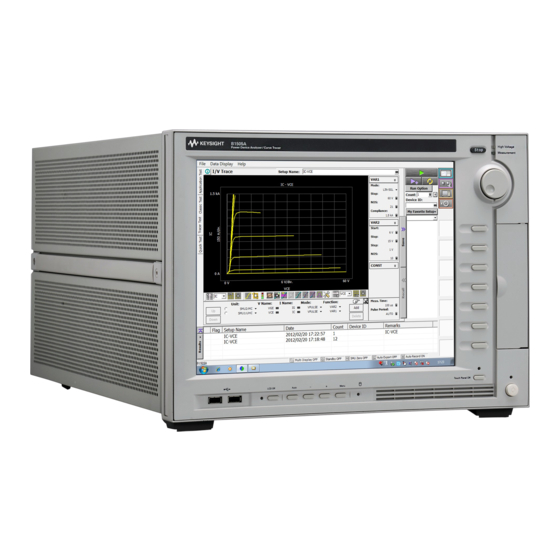
Keysight Technologies B1505A Configuration Manual (298 pages)
Power Device Analyzer/Curve Tracer
Brand:
Keysight Technologies
| Category:
Measuring Instruments
| Size: 8.67 MB
Table of Contents
Table of Contents
5
Measurement Resources
11
B1505A Mainframe Furnished Accessories
13
B1505A Modules and Mainframe Options
15
Module Type and Locations
17
N1259A Test Fixture for Power Device
19
N1265A Ultra High Current Expander/Fixture
25
N1266A High Voltage Source Monitor Unit Current Expander
33
N1266A Compatibility with Fixture and Module Selector
35
Fast Switch
37
N1268A Ultra High Voltage Expander
39
N1271A Thermal Test Enclosure and Related Accessories
43
Measurement Capability on Thermal Test
47
Information of Intest Thermal Plate and Thermostream
47
Modules/Fixture)
48
Pre-Configured Power Device Analyzer/Curve Tracer
48
Accessories for Wafer Prober and Your Own Test Fixture
56
Other Accessories
65
Retrofit Products for B1505A
69
Conversion Kit from B1500A to B1505A
72
Upgrade Kit for N1259AU Test Fixture
73
Upgrade Kit for N1265AU Test Fixture
77
Note for 4142B Users
82
N1259A Connection Guide
83
Input Connection
85
To Connect Interlock Circuit
86
Output Connection
90
To Connect DUT
91
To Use Options
94
N1259A-010 Inline Package Socket Module
101
N1259A-011 Universal Socket Module
102
N1259A-012 Blank PTFE Board
103
N1259A-013 Curve Tracer Test Adapter Socket Module
104
N1259A-014 Gate Charge Socket Module
105
N1265A Connection Guide
107
Input Connection
110
To Connect Interlock Circuit
111
Output Connection
115
To Connect DUT
116
Inline Package Socket Module (N1265A-010)
123
Universal Socket Module (N1265A-011)
124
Curve Tracer Test Adapter Socket Module (N1265A-013)
125
Gate Charge Socket Module (N1265A-014)
126
Blank Silicon Plate (N1265A-002)
128
Universal R-Box (N1265A-035)
129
Protection Adapter (N1265A-040)
131
Container (N1265A-045)
131
Prober System Cable (N1254A-524)
131
N1272A and N1273A Connection Guide
133
Input Connection
135
To Connect Interlock Circuit
135
N1272A Device Capacitance Selector
135
Output Connection
140
To Connect DUT
140
3-Pin Inline Package Socket Module
141
N1273A-011 Universal Socket Module
143
N1273A-013 Curve Tracer Test Adapter Socket Module
146
Accessories for Connecting a DUT
147
Connection Guide for Wafer Prober and Your Own Test Fixture
149
Connection Overview
152
To Connect High Voltage R-Box
162
To Use Universal R-Box
163
To Connect HCSMU Adapter
165
To Connect Dual HCSMU Adapter
168
To Connect 16493S-020
168
To Connect 16493S-021
170
To Connect Protection Adapter
171
To Connect High Voltage Bias Tee
173
To Connect Module Selector
175
To Connect HVSMU/HCSMU Fast Switch
180
To Connect HVSMU Current Expander
182
To Connect Ultra High Current Expander
184
Connecting System Cable to N1265A
185
To Connect Ultra High Voltage Expander
186
To Connect Device Capacitance Selector
188
To Connect Gate Charge Adapter
191
To Connect N1274A
192
To Connect N1275A
193
To Install an Interlock Circuit
195
Procedure
196
To Connect Interlock Circuit
197
About Cable Connections
198
To Make Connection to Reduce Leakage Current
199
To Make Connection to Measure Low Resistance
200
To Connect UHVU/HVSMU/HVMCU Output
201
Accessory Dimensions
203
Connection and Ordering Examples
219
Package Device Measurement Configuration Examples
221
3Kv, 20A Configuration (B1505AP-H20 Equivalent)
222
3Kv, 20A with Capacitance Measurement Configuration
224
Kv, 500 a or 1500 a Configuration (B1505AP-H50 or B1505AP-H70 Equivalent)
226
Kv, 500 a or 1500 a with Capacitance Measurement Configuration (B1505AP-H51 or B1505AP-H71 Equivalent)
228
Kv, 500 a or 1500 a Configuration
230
Add High Resolution Measurement (10 Fa Resolution with MPSMU or HPSMU) Capability to 3 Kv, 20 a Configuration
232
Kv, 20A, High Voltage Medium Current Configuration
234
Kv, 40 a Configuration
236
Add High Resolution Measurement Capability (10 Fa Resolution with MPSMU or HPSMU) to 3 Kv, 500A Configuration
239
Kv, 500 A, High Voltage Medium Current Configuration
241
Configuration Examples for Lateral Device Measurement with Wafer Prober
243
Kv, 20 a Measurement for On-Wafer Lateral Device
244
Kv, 20 A, Capacitance Measurement for On-Wafer Lateral Device
248
Add High Resolution Measurement (10 Fa Resolution with MPSMU or HPSMU) Capability to 3 Kv, 20 A, Capacitance Measurement for On-Wafer Lateral Device
251
Kv, 40 a Measurement for On-Wafer Lateral Device
253
Kv, 500 a Measurement for On-Wafer Lateral Device
256
Kv, 500 A, Capacitance Measurement for On-Wafer Lateral Device
258
Lateral Device
258
10 Kv, 500 a Measurement for On-Wafer Lateral Device
262
Configuration Examples for Vertical Device Measurement with Wafer Prober
264
Kv, 20 a Measurement for On-Wafer Vertical Device
265
Kv, 20 A, Capacitance Measurement for On-Wafer Vertical Device
269
Add High Resolution Measurement (10 Fa Resolution with MPSMU or HPSMU) Capability to 3 Kv, 20 A, Capacitance Measurement for On-Wafer Vertical Device
272
Kv, 40 a Measurement for On-Wafer Vertical Device
274
Kv, 500 a Measurement for On-Wafer Vertical Device
277
Kv, 500 A, Capacitance Measurement for On-Wafer Vertical Device
278
Vertical Device
278
10 Kv, 500 a Measurement for On-Wafer Vertical Device
282
Gan Current Collapse / Dynamic On-Resistance Measurement System
284
Non-Kelvin Connection with the N1259A Test Fixture for Package Device
284
Using the N1267A
284
Kelvin Connection with the N1259A Test Fixture for Package Device
286
Non-Kelvin Connection with Prober for On-Wafer Lateral Device
288
Kelvin Connection with Prober for On-Wafer Lateral Device
290
Upgrading from Existing B1505A
292
Example of How to Upgrade Existing B1505A
294
Advertisement
Keysight Technologies B1505A User Manual (266 pages)
Power Device Analyzer / Curve Tracer
Brand:
Keysight Technologies
| Category:
Measuring Instruments
| Size: 4.21 MB
Table of Contents
Table of Contents
25
1 Getting Started
29
To Turn On/Off B1505A
31
To Turn B1505A on
32
To Turn B1505A off
32
To Launch Easyexpert
34
If Only One Workspace Exists
35
To Create Workspace
36
To Select Workspace
37
To Use Tracer Test Mode
38
To Use Application Test Mode
40
To Use Classic Test Mode
42
To Perform Measurement
44
To Use Test Result Editor
45
To Use Analysis Tools
46
2 Introduction
47
Overview
49
Keysight Easyexpert Software
53
Front View
55
Rear View
58
Accessories and Options
65
Measurement Resources
73
GNDU - Ground Unit
73
About SMU
74
HPSMU - High Power SMU
75
HCSMU - High Current SMU
78
HVSMU - High Voltage SMU
80
MPSMU - Medium Power SMU
82
MCSMU - Medium Current SMU
85
HVMCU - High Voltage Medium Current Unit
87
UHCU - Ultra High Current Unit
89
UHVU - Ultra High Voltage Unit
91
MFCMU - Multi Frequency CMU
93
3 Accessories
97
N1258A Module Selector
100
N1259A Test Fixture
105
N1260A High Voltage Bias-Tee
122
N1261A Protection Adapter
123
N1262A Resistor Box
124
16493S-010/011 HCSMU Adapter
126
16493S-020/021 Dual HCSMU Adapter
127
N1265A Ultra High Current Expander/Fixture
129
N1266A HVSMU Current Expander
151
N1267A HVSMU/HCSMU Fast Switch
154
N1268A Ultra High Voltage Expander
163
N1269A Ultra High Voltage Connection Adapter
166
N1271A Thermal Test Enclosure
167
N1272A Device Capacitance Selector
179
N1273A Capacitance Test Fixture
183
N1274A On-Wafer Gate Charge Measurement Adapter/Selector for
195
N1275A On-Wafer Gate Charge Measurement Adapter for N1265A
199
4 Installation
201
Requirements
205
Power Requirements
205
Operating Environment
205
Storaging/Shipping Environment
205
Installation Requirements
206
Power Cable
207
Inspection and Installation
209
To Inspect B1505A and Accessories
209
To Perform Initial Setup
210
To Change Windows Logon Setting
211
To Change GPIB Address
212
To Enable System Controller
213
Maintenance
214
Cleaning
214
Self-Test and Diagnosis
214
Calibration
215
About Plug-In Modules
216
5 Measurement Examples
219
Gate Charge Measurement
221
Preparing Measurement
221
System Configuration and Open/Short Calibration
223
Preparing Measurement Setups and Performing Measurements
223
Packaged Device Testing Using Current Load Transistor on the N1259A-014 or N1265A-014
224
Packaged Device Testing Using Resistive Load on the N1259A-014 or N1265A-014
227
On-Wafer Auto-Testing Using Current Load Transistor on the N1274A
228
On-Wafer Auto-Testing Using Resistive Load on the N1274A
229
On-Wafer Auto-Testing Using Current Load Transistor on the N1275A
231
On-Wafer Auto-Testing Using Resistive Load on the N1275A
235
Available Application Test List
239
I-V and Capacitance Measurements Using N1272A
242
Preparing Measurement
242
System Configuration and Open/Short Calibration
244
Preparing Capacitance Measurement Setups
245
Performing Capacitance Measurement
246
Preparing IV Measurement Setups
247
Performing IV Measurement
248
Available Application Test List
249
Temperature Controlled by Thermal Plate
251
Preparing Measurement
251
Preparing Temperature Control and Measurement Setups
253
Performing Temperature Control and Measurement
255
Available Application Test List
256
Temperature Controlled by Thermostream
257
Preparing Measurement
257
Preparing Temperature Control and Measurement Setups
259
Performing Temperature Control and Measurement
261
Available Application Test List
262
Using Multiple HVSMU Modules
263
HVSMU Output Range
263
Setting Output Range Mode
264
Performing Measurement
264
Available Application Test List
264
Keysight Technologies B1505A Handbook (128 pages)
Power Device Analyzer/Curve Tracer
Brand:
Keysight Technologies
| Category:
Measuring Instruments
| Size: 10.14 MB
Table of Contents
Table of Contents
5
Chapter 1. Basic Knowledge of the B1505A
7
Agilent B1505A Power Device Analyzer/Curve Tracer
7
Agilent N1259A Power Device Fixture
9
Easyexpert Software
11
Application Test
11
Classic Test
12
Tracer Test
13
Chapter 2. Preparation for the Measurements
15
Before Using the B1505A
15
Instruments and Accessories Used in the Measurement Examples
16
Devices Used in the Measurement Examples
19
Cable Connection between the B1505A and the N1259A Test Fixture
20
Table of Contents
21
Step
22
Step
23
Step
24
Starting the B1505A
25
Step
25
Step
26
Step
27
Chapter 3. Measurements of Data Sheet Specifications of Power Bjts
36
Application Test Example
36
IC - Vce Measurement
36
Hfe and Vbe(On) Versus IC Measurement
47
Vce(Sat) and Vbe(Sat) Versus IC Measurement
51
Vce(Sus) or V(Br)Ceo, and Iceo-Vce Measurement
54
Bvcbo and Icbo-Vcb Measurement
66
Bvebo and Iebo-Veb Measurement
71
Bvces and IC-Vces Measurement
76
Cob-VC Measurement
81
IC-Vce Tracer Test
87
Advertisement
Advertisement
Related Products
Keysight Technologies B1507A
Keysight Technologies B1500A
Keysight Technologies Option B1X
Keysight Technologies B2902A
Keysight Technologies B2981A/83A
Keysight Technologies B2985A/87A
Keysight Technologies B2987A
Keysight Technologies B2985A
Keysight Technologies B2981A
Keysight Technologies Option B85
Keysight Technologies Categories
Measuring Instruments
Test Equipment
Control Unit
Portable Generator
Power Supply
More Keysight Technologies Manuals
Login
Sign In
OR
Sign in with Facebook
Sign in with Google
Upload manual
Upload from disk
Upload from URL