
Related Manuals for Keysight Technologies B1505A


Summary of Contents for Keysight Technologies B1505A
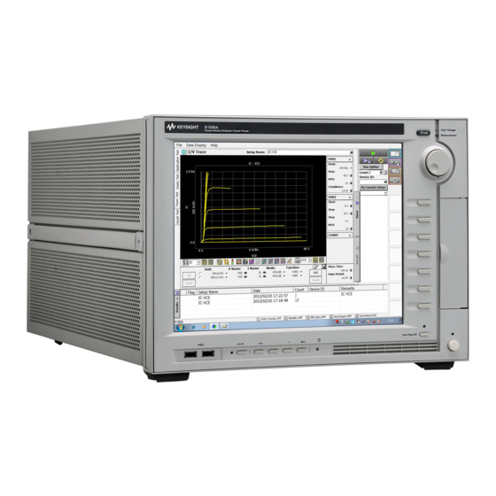
- Page 1 Keysight Technologies B1505A Power Device Analyzer/Curve Tracer Step by Step Measurement Handbook for Power BJT...
- Page 3 They can be downloaded from the Agilent web site and you can use them by importing to your B1505A. They include the Appli- cation Test library and the test definitions, and you can start measurements right away.
- Page 4 Table 1. Typical DC and Capacitance parameters of power BJT and the compatibility of the B1505A. Typical power BJT Parameter Symbol Unit Measurement* Typical Measurable Range of B1505A -40 A to 40 A Collector Current Ic-Vce (Minimum 10 fA resolution) *...
-
Page 5: Table Of Contents
2-2. Instruments and Accessories used in the measurement examples 2-3. Devices used in the measurement examples 2-4. Cable Connection between the B1505A and the N1259A Test Fixture 2-5. Starting the B1505A Chapter 3. Measurements of Data Sheet Specifications of Power BJTs 3-1. - Page 6 Appendix 2. Preparation for the Measurements using the Module Selector A2-1. Instruments and Accessories used in the measurement examples A2-2. Cable Connection between the B1505A and the N1259A Test Fixture A2-3. Connection inside the N1259A Test Fixture Appendix 3. Configuration for 40 A output A3-1.
-
Page 7: Chapter 1. Basic Knowledge Of The B1505A
B1505A, provides an intuitive and flexible data man- agement and analysis environment. B1505A has 10 module slots, which support the following modules B1510A High Power SMU (HPSMU) 10 fA~1 A/2 µV~200 V B1512A High Current SMU (HCSMU) 10 pA~1 A/200 nV~40V (DC) or 10 pA~20 A/200 nV~20 V (Pulse) B1513A High Voltage SMU (HVSMU) 10 fA~4 mA/200 µV~3000 V or 10 fA~8... - Page 8 Output and measurement range of each module are visually shown in figure 1-1. (A) HPSMU Output and Measurement range Current 500mA 125mA Voltage 200V -200V -100V 100V (B) HCSMU Output and Measurement range (C ) HVSMU Output and Measurement range Current Current Pulse...
-
Page 9: Agilent N1259A Power Device Fixture
Agilent N1259A Power Device Fixture shown in fig- ure 1-2 is used for measuring packaged power de- vices, It can basically covers the B1505A`s maximum output range; 40 A and 3 kV. We use N1259A option 020 High Voltage Bias-Tee and option 022 100 kΩ... - Page 10 Note: We are not using Option 300 Module Selector which is convenient for automatically switching the meas- urement resources between the HVSMU, HCSMU and HPSMU without manually re-connecting the cables between the power BJT and each SMU. Figure 1-5 shows a simplified image of Module Selector con- nected to the collector of the power BJT.
-
Page 11: Easyexpert Software
The Application Test mode shown in figure 1-6 is a pre-defined test library coming with the B1505A and it includes a basic and frequently used test, for example, Id-Vd measurements. The user can start measurements by just typing in the measurement parameters and the test results with a proper data which is automatically extracted by the measurement is coming out by just pressing the Measure button. -
Page 12: Classic Test
Classic Test mode Classic Test is used inside of the Application Test definition as a main measurement engine for defining and executing a test. Classic Test can be used itself as a stand- alone test engine and it can define a unique test. The user interface of the Classic Test mode adopts the same concept of the Agilent Semiconductor Parameter Ana- lyzers and anyone can get used to handle this interface easily. -
Page 13: Tracer Test
Test mode, you can change the measurement parameters while the test is repeat- edly executed, for example, the collector voltage of the Id-Vd sweep can be manu- ally changed by rotating a knob of the B1505A like rotating a voltage dial of the curve tracer. - Page 14 There are other ways for using the Tracer Test mode. Since the Tracer Test setup can be easily converted to a Classic Test setup, You can use Tracer Test mode as an easy test setup and test debugging tool. The example test setup features will automatically set complicated test setup, and the interactive measurement control features help for debugging the new test setup.
-
Page 15: Chapter 2. Preparation For The Measurements
● minals, turn the B1505A off and discharge any capacitors. If you do not wish to turn the B1505A off, complete all of the following items, regardless of the B1505A settings. - Press the Stop key to turn the module output off. -
Page 16: Instruments And Accessories Used In The Measurement Examples
2-2. Instruments and Accessories used in the measurement examples We use the following two B1505A configurations in the measurement example, Both configurations are used for 20 A collector output. The difference is the maxi- mum base current is limited to 1 A in the configuration of figure 2-1(A) that uses two HPSMUs and one HCSMU, but the other configuration that uses one HPSMU and two HCSMUs (figure 2-1(B)) can drive more than 1A by using one of HCSMUs. - Page 17 ● 1 X N1300A CMU Cable ● 1 X 16493J Interlock Cable ● 16493T HV Triax 16494A Triax Cable N1300A CMU Cable 16493T HCSMU Cable 16493J Interlock Cable Figure 2-3. Cables used for connecting between the B1505A and the N1259A...
- Page 18 Optional Items: The following adapter and the cable are required for configuring the 40 A solution by using two HCSMU modules. The configuration for 40A solution is introduced in the appendix section. Optional accessories (for 40A configuration only) 1 X 16493S Opt 021 Dual HCSMU Combination Adapter ●...
-
Page 19: Devices Used In The Measurement Examples
B1505A`s performance in a wide range of applications. Even in case a different power BJT is used, the example test setup of this handbook is not being affected by which power BJT is used, and the user can just enter appro- priate parameters depending on the specification of the power BJT used. -
Page 20: Cable Connection Between The B1505A And The N1259A Test Fixture
Figure 2-6. Connections for 2x HPSMU and 1x HCSMU Configuration. This configuration is used when only one HCSMU is installed in the B1505A. Connect the cables between the B1505A and the N1259A as shown in figure 2-6 by following the step number 1 to 6. - Page 21 For disconnecting the interlock cable, hold the metal part and then pull the connector by turning it. Step 1 Step 2 Step 3 Step 4 Step 5 Step 6 Figure 2-7. Breakdown of the cable connection for 20 A configuration. For connecting: For disconnecting: Pressing and...
-
Page 22: Step
Step number 2: Using a 16493L GNDU Cable, connect the GNDU on the B1505A to the GNDU1 Input on the N1259A. Step number 3: Using a 16494A Triax Cable, connect the Force and Sense connectors on the lower B1510A HPSMU (SMU1) to the respective connectors on the HPSMU1 input of the N1259A. -
Page 23: Step
1 A, can drive the base sufficiently to fully swing the collector of the power BJT. Connect the cables between the B1505A and the N1259A as shown in figure 2-9 by following the step number 1 to 7. -
Page 24: Step
Figure 2-10. Breakdown of the cable connection for 1 x HPSMU and 2 x HCSMU 20 A configuration. 2-4-3. Power cable, Keyboard and mouse Be sure connecting power cable, keyboard and a mouse before starting the B1505A. Key Board Mouse Power Cable Figure 2-11. -
Page 25: Starting The B1505A
PERT Software" page opens as shown in figure 2-12. Figure 2-12. Workspace management page. If your B1505A directly opens one of your EasyEXPERT workspaces as shown in figure 2-13, then follow the steps shown in "How to return to Workspace Manage- ment page."... -
Page 26: Step
If this operation is on your B1505A, you can practice without contaminating your existing workspace by adding unnecessary measurement setup and data. -
Page 27: Step
2-5-1-2 EasyEXPERT configuration before starting a measurement Before starting a measurement, check the configuration for HCSMU and the module IMPORTANT selector. You can view and change the configuration as follows. 1. Click the configuration button on the right side of the screen. 2. - Page 28 Copying the example file-set to Windows® - Copy the downloaded "B1505A_P-BJT_HB_Library.zip" file to a proper folder of the B1505A`s Windows® folder, say D:/tmp or desktop. 2-5-2-2 Extracting from zip compressed file The downloaded "B1505A_P-BJT_HB_Library.zip" file has to be extracted to the regular Windows®...
- Page 29 1. Right click zip file 2. Select “Extract All” 3. Press “Next” 5. Zip file is extracted 4. Select the folder to extract files Figure 2-17. Extracting the downloaded zip file.
- Page 30 The other type of new application test definitions are new for measuring the power BJT device specifications which were not included in the B1505A. 2. Application Test, Classic Test and Tracer Test setup files Example_AT.xpg...
- Page 31 2-5-2-3 Importing the example files to the EasyEXPERT software There is an installing order for the imported files to EasyEXPERT. Please import the example application test library at first before importing the test setup or example measurement data. 1. Importing the example application test library The example test library is installed in the existing PowerBJT application category.
- Page 32 1. Press “Library” 2. Select “Import Test Definition” 3. Find the imported library set 6. Check “PowerBJT” 7. New Application Test Definitions 5. Press “Open” 4. Select all files Figure 2-18. Importing the Application Test definitions.
- Page 33 2-5-2-4 Importing example test setup files The example file set includes the test setups used in the example and the test setup files are imported to a preset group of My Favorite Setup. Example test setup files include two types of setup data. One is test setup of the Application Test definitions for each corresponding data sheet specifications used in the example.
- Page 34 1. Press “My Favorite Setup” 2. Select “Preset Group” 3. Press “Import Preset Group” 4. Find the imported setup files 5. Select one file at once and press “Open” button “Example-AT” and ” Example -CT” preset groups and the associated setup files are imported in each group “Example-AT”...
- Page 35 2-5-2-5 Importing example measurement data Measurement data used in the examples in the handbook are included in the exam- ple file set. If you import the data to the Results windows of EasyEXPERT, you can easily ex- plore the EasyEXPERT functionality with a real measurement data. [PROCEDURE] –...
-
Page 36: Chapter 3. Measurements Of Data Sheet Specifications Of Power Bjts
Chapter 3. Measurements of Data Sheet Specifications of Power BJTs This chapter demonstrates how the B1505A measures the power BJT parameters in the data sheet specifications. The test parameters included in this measurement handbook are listed next catego- rized in four measurement groups. - Page 37 General Idea of measurement using the EasyEXPERT software Figure 3-1 shows the general idea of measurement using the EasyEXPERT Applica- tion Test Library. The idea is straight forward and easy to use; Step 1. Choose device type or application category from the Category field. Or, just from step 1` where your unique setup has been saved in My Favorite Setup field, and you can just start from here by just selecting a setup icon and skip step 2 and go to step 3 Measure.
- Page 38 3-1. Measurement using Application Test mode This chapter demonstrates the following measurements using the Application Test mode library. Ic-Vce(PowerBJT): Ic versus Vce measurement ● hFE_Vbe-Ic hFE and Vbe versus Ic measurement. ● Extracts hFE and Vbe_On. Vce(sat)-Ic 2 Vce and Vbe versus Ic measurement. ●...
- Page 39 A. Common cable configuration for Ic-Vce, hFE_Vbe-Ic and Vce(sat)-Ic 2 with HPSMU (base) and HCSMU (collector) connection: Open the N1259A test fixture cover, and connect the test leads shown in figure 3-2 by following the step numbers as shown in figure 3-3 and the following procedure steps.
- Page 40 1 x HPSMU and 1 x HCSMU configuration HPSMU1 HCSMU1 AUX1 HVSMU1 Force Sense Force Signal Sense Force High Guard Guard GNDU1 1 1 1 AUX2 HCSMU2 HPSMU2 Sense Force Force Signal Force High Sense Guard Sense Agilent N1259A opt 033 Agilent N1259A opt 022 Agilent N1259A opt 010 Force...
- Page 41 B. Common configuration for Ic-Vce, hFE_Vbe-Ic and Vce(sat)-Ic 2 with 2 x HCSMUs for the base and the collector connection: Open the N1259A test fixture cover, and connect the test leads shown in figure 3-2 by following the step numbers as shown in figure 3-4 and the following procedure steps.
- Page 42 2 x HCSMU configuration HPSMU1 HCSMU1 AUX1 HVSMU1 Force Sense Force Signal Sense Force High Guard Guard GNDU1 1 1 1 AUX2 HCSMU2 HPSMU2 Sense Force Force Signal Force High Sense Guard Sense Agilent N1259A opt 033 Agilent N1259A opt 022 Agilent N1259A opt 010 Force 100 k...
- Page 43 3-1-1. Ic - Vce measurement Measurement Parameters: General Ic-Vce characteristics Application Test name: Ic-Vce(PowerBJT) (Ic-Vce characteristics) Application Test setup name (My Favorite Setup -> Example_AT): Ic-Vce (PowerBJT) Device used in the example: MJL4281AG Connection inside the N1259A Test Fixture: Use figure 3-3 or 3-4 Application description: Measures Ic-Vce characteristics.
- Page 44 Step 3,4. Select Ic-Vce(PowerBJT) (Click the Ic-Vce(PowerBJT) then click Select Step 5. Set the test parameters shown in figure 3-5 to an appropriate one depending on your B1505A configuration and your test device. The important check points are; a. Base SMU setup b.
- Page 45 HCSMU connected to the collector, but it is also very close to the limit of HPSMU connected to the base terminal. The maximum collector current of the B1505A can be expanded to 40 A by connect- ing two HCSMUs in parallel, but the maximum 1 A base current of HPSMU limits the maximum collector current around 20 A even if you use 40A configuration that is shown in appendix section if you use this example powerBJT.
- Page 46 A`. Measurement Procedure: Ic-Vce(Power BJT) Application Test, - Starting from pre-defined test setup of My favorite Setup This test approach starts measurements by using a pre-defined test setup saved in My favorite Setup instead of starting from a scratch by using an Application Test Library.
-
Page 47: Hfe And Vbe(On) Versus Ic Measurement
Step 3,4. Select hFE_Vbe-Ic (Click the hFE_Vbe-Ic then click Select Step 5. Set the test parameters shown in figure 3-7 to an appropriate one depending on your B1505A configuration and your test device. The important check points are; a. Base SMU setup b. - Page 48 1. Starting from Application Test Library 1`. Starting from My Favorite Setup Go to Figure 3-7. hFE_Vbe-Ic application test setup.
- Page 49 c. Scale parameter: You can choose "Linear" or "LOG" sweep selection. The hFE measure- ment is typically made in a few decades of wide measurement range in the collector current, and LOG10 or LOPG25 which measures 25 points in a decade of Ib sweep span would be a reasonable choice. d.
- Page 50 Marker readings Extracted parameters Marker for hFE and Vbe Figure 3-8. hFE_Vbe-Ic application test data example Review: The hFE specification of MJL4281AG used in the example is minimum 50 at 8 A and 5 V collector measurement condition. The extracted hFE is 74.9 and it exceeds the minimum specification limit.
-
Page 51: Vce(Sat) And Vbe(Sat) Versus Ic Measurement
Step 3,4. Select Vce(sat)-Ic 2 (Click the Vce(sat)-Ic 2 then click Select Step 5. Set the test parameters shown in figure 3-9 to an appropriate one depending on your B1505A configuration and your test device. The important check points are;... - Page 52 1. Starting from Application Test Library 1`. Starting from My Favorite Setup Go to Figure 3-9. “Vce(sat)-Ic 2 “ application test setup. Extracted parameters Marker for Vce(sat) and Vbe(sat) Figure 3-10. “Vce(sat)-Ic 2 “ application test results.
- Page 53 Step 6. Make sure the device is properly selected as shown in the "Device used in the example" part or your selection. Close the lid of N1259A test fixture. Start the measurement. (Click the Single button Step 7. The graph window pops up, and the measurement starts. Step 8.
-
Page 54: Vce(Sus) Or V(Br)Ceo, And Iceo-Vce Measurement
3-1-4. Vce(sus) or V(BR)ceo, and Iceo-Vce measurement Measurement Parameters: Vce(sus) or V(BR)ceo Collector-Emitter sustaining voltage or Collector-Emitter breakdown voltage Iceo Collector-Emitter Cut-off current Application Test name: Ic-Vceo_R Application Test setup name: (My Favorite Setup -> Example_AT): Ic-Vceo_R or Ic- Vceo_R(+R value) Device used in the example: MJL4281AG Connection inside the N1259A Test Fixture: Use the figure shown in this section Application description:... - Page 55 [PROCEDURE] Step 1. Insert the power BJT (example: MJL4281AG) into the socket on the N1259A. Make sure the device pin name matches to the socket numbers shown in figure 3-11. Step 2. Connect the Force of the HVSMU1 to the terminal 2 Force (Collector) on the Inline Package Socket.
- Page 56 B. Connection inside the N1259A Test Fixture: 100 kΩ Ω Ω Ω Use the following connection inside the N1259A test fixture Open the N1259A test fixture cover, and connect the test leads shown in figure 3-3 by following the step numbers as shown in figure 3-12 and the following procedure steps.
- Page 57 3-1-4-A. Measurement Procedure: Ic-Vceo_R Application Test without series collector resistor Use figure 3-11 connection inside the N1259A Test Fixture. A. Starting from Application Test Library This test approach starts measurements by using an Application Test Library, which starts from the default setup parameters, and you have to customize the measure- ment parameters depending on your requirements.
- Page 58 There is no hazard at this moment because the measurement is not yet started, but make sure the red High Voltage light on the B1505A front panel and the Shock Hazard warning light of the N1259A Test Fixture is not lit.
- Page 59 Figure 3-14 plots Icollector versus Vce. The VBceo and Iceo are automatically ex- tracted at the specified condition, and the parameters are shown in the Parameters display field. Note: Trace is jumped. Extracted BVceo and Iceo Marker at breakdown Magnified view Figure 3-14.
- Page 60 A`. Measurement Procedure: Ic-Vceo_R Application Test without series collector resistor. - Starting from pre-defined test setup of My favorite Setup This test approach starts measurements by using a pre-defined test setup saved in My favorite Setup instead of starting from a scratch by using an Application Test Library.
- Page 61 Step 3,4. Select Ic-Vceo_R (Click the Ic-Vceo_R then click Select Step 5. Set the test parameters shown in figure 3-15 to an appropriate one depend- ing on your B1505A configuration and your test device. The important check points are; a. Collector SMU setup b.
- Page 62 There is no hazard at this moment because the measurement is not yet started, but make sure the red High Voltage light on the B1505A front panel and the Shock Hazard warning light of the N1259A Test Fixture is not lit.
- Page 63 1. Starting from Application Test Library 1`. Starting from My Favorite Setup Go to Figure 3-15. Ic-Vceo_R Application Test setup with 100 kΩ Ω Ω Ω series collector resistor.
- Page 64 Extracted BVceo and Iceo Marker at breakdown Note: Trace is continuous. Figure 3-16. Ic-Vceo_R test results with 100 kΩ Ω Ω Ω series collector resistor. Review: The measured VBceo is 397.8 V and this is very close to the previous A section`s results.
- Page 65 B`. Measurement Procedure: Ic-Vceo_R Application Test - Starting from pre-defined test setup of My favorite Setup This test approach starts measurements by using a pre-defined test setup saved in My favorite Setup instead of starting from a scratch by using an Application Test Library.
-
Page 66: Bvcbo And Icbo-Vcb Measurement
3-1-5. BVcbo and Icbo-Vcb measurement Measurement Parameters: BVcbo, Icbo Collector- Base voltage, Collector- Base Cut-off Current Application Test name: Ic-Vcbo 2 Application Test setup name: (My Favorite Setup -> Example_AT): Ic-Vcbo 2 Device used in the example: MJL4281AG Connection inside the N1259A Test Fixture: Use the figure shown in this section Application description: Measures Collector current vs. - Page 67 HPSMU1 HCSMU1 AUX1 HVSMU1 Force Sense Force Signal Sense Force High Guard Guard GNDU1 1 1 1 AUX2 HCSMU2 HPSMU2 Sense Force Force Signal Force High Sense Guard Sense Agilent N1259A opt 033 Agilent N1259A opt 022 Agilent N1259A opt 010 Force 100 k Sense...
- Page 68 Step 3,4. Select Ic-Vcbo 2 (Click the Ic-Vcbo 2 then click Select Step 5. Set the test parameters shown in figure 3-18 to an appropriate one depend- ing on your B1505A configuration and your test device. The important check points are;...
- Page 69 1. Starting from Application Test Library 1`. Starting from My Favorite Setup Go to Figure 3-18. “Ic-Vcbo 2” Application Test setup. Extracted BVcbo and Icbo Marker for BVcbo Figure 3-19. “Ic-Vcbo 2” application test display.
- Page 70 We sweep the collector voltage with the 100 ms hold time for waiting the first measurement with no additional delay time (means the default wait time determined by the B1505A). Please note that the leakage current measurement is affected by these wait time settings.
-
Page 71: Bvebo And Iebo-Veb Measurement
3-1-6. BVebo and Iebo-Veb measurement Measurement Parameters: BVebo, Iebo Emitter-base voltage, Emitter Cutoff current Application Test name: Ic-Vebo 2 Application Test setup name: (My Favorite Setup -> Example_AT): Ic-Vebo 2 Device used in the example: MJL4281AG Connection inside the N1259A Test Fixture: Use the figure shown in this section Application description: Measures Emitter current vs. - Page 72 HPSMU1 HCSMU1 AUX1 HVSMU1 Force Signal Force Sense Sense Force High Guard Guard GNDU1 1 1 1 AUX2 HCSMU2 HPSMU2 Sense Signal Force Force Force High Sense Guard Sense Agilent N1259A opt 033 Agilent N1259A opt 022 Agilent N1259A opt 010 Force 100 k Sense...
- Page 73 Step 3,4. Select Ic-Vebo 2 (Click the Ic-Vebo 2 then click Select Step 5. Set the test parameters shown in figure 3-21 to an appropriate one depend- ing on your B1505A configuration and your test device. The important check points are;...
- Page 74 1. Starting from Application Test Library 1`. Starting from My Favorite Setup Go to Figure 3-21. “Ic-Vebo 2” Application Test setup. Extracted BVebo and Iebo Marker for BVebo Figure 3-22. “Ic-Vebo 2” application test display.
- Page 75 Review: The Emitter cutoff current Iebo is typically very low even in power BJTs. The specifi- cation of MJL4281AG is maximum 5 µΑ at Veb=5 V. The measured Iebo is 157 pA which is much lower compared to the specification, but it is natural. The measured emitter to base breakdown voltage;...
-
Page 76: Bvces And Ic-Vces Measurement
3-1-7. BVces and Ic-Vces measurement Measurement Parameters: BVces, Ices Collector - Emitter voltage, Collector breakdown voltage BVces Application Test name: Ic-Vces 2 Application Test setup name: (My Favorite Setup -> Example_AT): Ic-Vces 2 Device used in the example: MJL4281AG Connection inside the N1259A Test Fixture: Use the figure shown in this section Application description: Measures Collector current vs Collector-Emitter voltage and extracts Collector- Emitter breakdown voltage. - Page 77 1 x HPSMU and 1 x HCSMU configuration HPSMU1 HCSMU1 AUX1 HVSMU1 Force Signal Force Sense Sense Force High Guard Guard GNDU1 1 1 1 AUX2 HCSMU2 HPSMU2 Sense Signal Force Force Force High Sense Guard Sense Agilent N1259A opt 033 Agilent N1259A opt 022 Agilent N1259A opt 010 Force...
- Page 78 Step 3,4. Select Ic-Vces 2 (Click the Ic-Vces 2 then click Select Step 5. Set the test parameters shown in figure 3-24 to an appropriate one depend- ing on your B1505A configuration and your test device. The important check points are;...
- Page 79 1. Starting from Application Test Library 1`. Starting from My Favorite Setup Go to Figure 3-24. “Ic-Vces 2” Application Test setup. Extracted BVces Marker for BVces Figure 3-25. “Ic-Vces 2” application test display.
- Page 80 Review: The Collector breakdown voltage BVces shows typically very close to the Bvcbo. There is no BVces specification for the MJL4281AG, but measured 543 V of BVces shown in figure 3-25 is reasonable compared with the 566 V of BVcbo shown in fig- ure 3-19 and the 397 V of BVceo shown in figure 3-16.
-
Page 81: Cob-Vc Measurement
3-1-8. Cob-Vc measurement Measurement Parameters: Cob Output capacitance Application Test name: Cob Application Test setup name: (My Favorite Setup -> Example_AT): Cob Device used in the example: MJL4281AG Connection inside the N1259A Test Fixture: Use the figure shown in this section Application description: Measures Base-Collector capacitance (Cob), and plots Cob-Vc characteristics. - Page 82 Test Lead SHV cable and SHV-Banana Adaptor Figure 3-26. Test Lead, SHV cable and SHV-Banana Adaptor for the N1259A Test Fixture. HPSMU1 HCSMU1 AUX1 HVSMU1 Force Sense Force Signal Sense Force High Guard Guard GNDU1 1 1 1 AUX2 HCSMU2 HPSMU2 Sense Force...
- Page 83 Step 3,4. Select Cob (Click the Cob then click Select Step 5. Set the test parameters shown in figure 3-28 to an appropriate one depend- ing on your B1505A configuration and your test device. The important check points are; a. Scale setup: Select LINEAR or LOG.
- Page 84 1. Starting from Application Test Library 1`. Starting from My Favorite Setup Go to Figure 3-28. Cob Application Test setup. Extracted Cob Marker for Cob Figure 3-29. Cob application test display.
- Page 85 Tips: The marker can be used for reading each collector current and voltage by rotating the rotary knob. You can read between the two measurement points by activating the marker`s Interpolation mode to ON status. Review: The measured CV curve shows typical pn junction characteristics. The extracted Cob is 240 pF at Vc=10 V and it is within the maximum specification of the Cob of MJL4281AG;...
- Page 86 3-2. Measurement using Classic Test and Tracer Test mode This chapter demonstrates the following measurement examples using the Classic Test mode and Tracer Test mode. Ic-Vce TT Ic versus Vce measurement using Tracer Test mode ● Vce(sat)-Ic_CT Vce(sat) and Vbe(sat) measurement using Classic Test ●...
-
Page 87: Ic-Vce Tracer Test
One of the features of Tracer Test mode is the interactive sweep control functional- ity using the rotary knob of the B1505A. It can control the sweep voltage or current while the measurement is repeatedly performed by continuously changing the maxi- mum sweep value by using the rotary knob. - Page 88 Step 2. Click the Preset group of My Favorite Setup. Step 3. Select Example_CT preset group. Step 4. Select IC-VCE TT (IC-VCE Tracer Test). Step 5. Press Recall button. Step 6. Pre-defined example IC-VCE TT Tracer Test setup opens. Note: Tracer Test uses one page concept for all the setups and the display of the test results.
- Page 89 Step 7. Set the test parameters shown in figure 3-32 to an appropriate one depend- ing on your B1505A configuration and your test device. The important check points are; a. Base and Collector SMU setup By clicking the target Unit area, Channel definition area is activated and you can set the SMUs selection by clicking button.
- Page 90 Expands VAR1 menu Menu bar can be scrolled easily by dragging the no mark filed (i.e. except SMU selection Figure 3-32. IC-VCE Tracer Test parameter setup. Marker Figure 3-33. IC-VCE TT Tracer Test example.
- Page 91 Interactive sweep control: You can control the sweep by manually by following the next steps; (See figure 3-34) Step 11. Activate Stop voltage of VAR1, and set the voltage to a lower safe voltage, say 10 V. Step 12. Start repeat measurement by pressing Repeat Measure button.
- Page 92 The example uses "Multi Channel I/V Sweep" Classic Test mode for syn- chronously sweeping both the collector current and the base current in pulsed mode. Step 6. Set Unit field appropriately depending on your B1505A and connection set- ups. If your B1505A is one HCSMU configuration (Note: maximum two HCSMUs are allowed in the configuration), set HCSMU to the collector supply as in the case of the example setup.
- Page 93 Step 7. Press Measurement Setup tab. You can change measurement parameters in this page. Step 8. Linear/Log sweep mode is set. The parameter is set to "LOG25" which sweeps and measures 25 points per decade between the Start and Stop value entered in the next step. Step 9.
- Page 94 tects the Y axis value of the measurement curve at the specified X axis point. Step 19. Press Display Setup tab. You can set the X-Y Graph, List Display and the Parameters of the meas- urement results in this page. Step 20.
- Page 95 Part of Figure 3-35. Vce(sat)-Ic Classic Test setups. Continue to next page.
- Page 96 Figure 3-35. Vce(sat)-Ic Classic Test setups.
- Page 97 23 24 Extracted parameters Marker for Vce(sat) and Vbe(sat) Figure 3-36. Vce(sat)-Ic classic test results. Review: The output data shown in figure 3-36 shows exactly the same results as the figure 3 -10. The difference is the Y axis is in linear scale in the case of figure 3-36, but figure 3-10 is drawn in Log scale.
- Page 98 3-2-3. 100 k Ω Ω Ω Ω resistor precision measurement for Vce(sus) Application Test Measurement Parameters: Resistor value Measures 100 kΩ resistor value better than 0.1 % error Application Test name: 100 kohm CT Application Test setup name (My Favorite Setup -> Example_CT): 100 kohm CT Device used in the example: 100 kΩ...
- Page 99 HPSMU1 HCSMU1 AUX1 HVSMU1 Force Sense Force Signal Sense Force High Guard Guard GNDU1 1 1 1 AUX2 HCSMU2 HPSMU2 Sense Force Force Signal Force High Sense Guard Sense Agilent N1259A opt 033 Agilent N1259A opt 022 Agilent N1259A opt 010 Force 100 k Sense...
- Page 100 A. Measurement Procedure: 100 kohm CT Classic Test Refer to figure 3-38 for the following Step 1 to Step 23. Step 1. Click the Preset group of My Favorite Setup. Step 2. Select Example_CT preset group. Step 3. Select 100 kohm CT (100 kohm CT Classic Test). Step 4.
- Page 101 Figure 3-38. 100 kohm CT Classic Test setups.
- Page 102 11 12 Extracted 100 kΩ resistor value Regression line to extract 100 kΩ value Figure 3-39. 100 kohm CT Classic Test Display. Review: The voltage and the current measurement accuracy of HVSMU in 1mA and 200 V range used in the application is better than 0.03 %. Therefore, the measured accu- racy of the resistor can be expected to be better than approximately 0.05% (~ SQRT (0.03^2 + 0.03^2).
- Page 103 Appendix 2. Preparation for the Measurements using the Module Selector A2-1. Instruments and Accessories used in the measurement examples A2-2. Cable Connection between the B1505A and the N1259A Test Fixture A2-3. Connection inside the N1259A Test Fixture Connection for common DC measurement ●...
- Page 104 - Download: By clicking the link, you can download "B1505A_P-BJT_HB_Library.zip" example file. Save it to a proper folder of the B1505A`s Windows® system, say D:/tmp or desk- top. For installing the file-set to the EasyEXPERT software, refer to the main section "2-5...
- Page 105 A1-2. How to return to Workspace management page This section provides the information for returning to "Workspace management page" from current operating EasyEXPERT workspace like as shown in figure 2-13. When starting the EasyEXPERT software, default setting opens Workspace management page as shown in figure 2-12. Figure A1-1 shows how you can return to EasyEXPERT Workspace management page.
- Page 106 A2-1. Instruments and Accessories used in the measurement examples HVSMU HCSMU MFCMU HPSMU Figure A2-1. B1505A 20 A configuration used in the example. HPSMU B1505A 20 A configuration uses following modules. Agilent B1505A Power Device Analyzer/Curve Tracer (20 A): 1 X HVSMU (B1513A) High Voltage SMU ●...
- Page 107 Figures A2-2. Cables used for connecting between the B1505A and the N1259A. Note: Even if your B1505A is one HPSMU and two HCSMU configuration, you can use module selector by replacing the second HPSMU to second HCSMU. In that case,...
- Page 108 Using a 16493G Digital I/O Cable, connect the Digital I/O connector on the B1505A to the Digital I/O connector on the N1259A test fixture. Step number 2: Using a 16493J Interlock Cable, connect the Interlock on the B1505A and the Interlock on the N1259A Tips:...
- Page 109 For disconnecting the interlock cable, hold the metal part and then pull the connector by turning it. Step number 3: Using a 16493L GNDU Cable, connect the GNDU on the B1505A to the GNDU1 Input on the N1259A. Step number 4:...
- Page 110 Step 1 Step 2 Step 3 Step 4 Step 5 Upper block of N1259A Step 6 Step 7 Coax Triax Triax Coax Step 8 Figure A2-4. Breakdown of the cable connection for 20 A configuration.
- Page 111 Therefore this checkbox should better be set to off, every time just after the use of this function, for preventing any unexpected test result in later use of the B1505A. d. Check the SMU modules e. After modification, press "Apply" button.
- Page 112 A2-3. Connection inside the N1259A Test Fixture A2-3-1. Common DC Measurement Use figure A2-6 connection for the following common DC measurement; Application Test mode: Ic-Vce ● hFE_Vbe-Ic ● Vce(sat)-Ic 2 ● Ic-Vces 2 ● Classic Test and Tracer Test mode: IC-VCE TT Tracer Test ●...
- Page 113 [PROCEDURE] Open the N1259A test fixture cover, and connect the test leads as follows. The num- bers on the drawing correspond to the procedure steps. Step 1. Insert the device (MJL4281AG) into the socket on the N1259A. Step 2. Connect the High Force of the Module Selector Output to the terminal 2 Force (Collector) on the Inline Package Socket.
- Page 114 A2-3-2. Other connections For other connections by using the module selector, use the following connections depending on the measurement parameters. For each connection, open the N1259A test fixture cover, and connect the test leads by following the numbers on the drawing. Note: There is no step by step connection instruction in this section.
- Page 115 Ic–Vcbo connection ● HPSMU1 HCSMU1 AUX1 HVSMU1 Force Signal Force Sense Sense Force High Guard Guard GNDU1 1 1 1 AUX2 HCSMU2 HPSMU2 Sense Force Force Signal Force High Sense Guard Sense Agilent N1259A opt 033 Agilent N1259A opt 022 Agilent N1259A opt 010 Force 100 k...
- Page 116 Cob application test connection. ● Use SHV cable and an adaptor for connections in step 5 and step 6. HPSMU1 HCSMU1 AUX1 HVSMU1 Force Sense Force Sense Signal Force High Guard Guard GNDU1 1 1 1 AUX2 HCSMU2 HPSMU2 Sense Force Force Signal...
- Page 117 The 40 A output is realized by connecting two HCSMUs in parallel using 16493S Opt 021 Dual HCSMU Combination Adapter. Therefore, 40 A configuration is possible only when two HCSMUs are installed in the B1505A as shown in figure A3-1. Use this configuration if your device requires more than 20 A current. Note: Limitation Two HCSMU configuration.
- Page 118 16493T HV Triax 16494A Triax Cable N1300A CMU Cable 16493T HCSMU Cable 16493J Interlock Cable 16493S Opt 021 16493S Opt 021 Cable (40 A option) (40 A option) Figure A3-2. Cables and Accessories used for connecting between the B1505A and the N1259A.
- Page 119 A3-2. Cable Connection between the B1505A and the N1259A Test Fixture Connect the cables between the B1505A and the N1259A as shown in figure A3-3 by following the step number 1 to 8. The breakdown of each steps with cable figures and the connector locations are shown in figure A3-4.
- Page 120 Step number 2: Using a 16493L GNDU Cable, connect GNDU on the B1505A to the GNDU1 Input on the N1259A. Step number 3: Using a 16494A Triax Cable, connect the Force and Sense connectors on the lower B1510A HPSMU (SMU1) to the respective connectors on the HPSMU1 input of the N1259A.
- Page 121 Step 1 Step 2 Step 3 Step 4 Step 5 Lower side HCSMU Triax Coax Coax Triax Step 6 Higher side HCSMU Triax Coax Coax Triax Step 7 Coax Triax Triax Coax Step 8 Figure A3-4. Breakdown of the cable connection for 40 A configuration.
- Page 122 A3-3. EasyEXPERT configuration before starting a measurement Before starting a measurement, check the configuration for HCSMU and the module IMPORTANT selector. You can view and change the configuration as follows. Click the configuration button on the right side of the screen. Select the “Dual HCSMU Combination”...
- Page 123 1. Select “SMU Output Limit Setting” tab 2. Set to 40 A Figure A3-6. 40 A Configuration setting 2. 1. Select “Module Selector” tab 2. Uncheck “Enable” Figure A3-7. Module Selector setting.
- Page 124 Appendix 4. Before returning the demo-B1505A If your practice of this measurement handbook is with an Agilent demo-B1505A, you may want to keep your measurement data for future reference and want to delete your foot print from the demo-B1505A before returning it to Agilent.
- Page 125 Figure A4-1. Expanding the Results area and select measurement data sets.
- Page 126 A4-2. Deleting the workspace and measured data Deleting of your foot print from the demo-B1505A is easiest by deleting your work- space from the Workspace management page. You can open the Workspace management page by standard startup process or us- ing the methods shown in appendix section A1-2.
- Page 128 This information is subject to change without notice. © Keysight Technologies 2011, 2014 *B1505-90070* B1505-90070 www.keysight.com...
Need help?
Do you have a question about the B1505A and is the answer not in the manual?
Questions and answers