Keysight Technologies B1500A User Manual
Semiconductor device analyzer
Hide thumbs
Also See for B1500A:
- Self-paced training manual (188 pages) ,
- Configuration and connection manual (122 pages) ,
- Connection manual (34 pages)
Table of Contents
Advertisement
Quick Links
Advertisement
Table of Contents

Related Manuals for Keysight Technologies B1500A


Summary of Contents for Keysight Technologies B1500A
- Page 1 Keysight Technologies B1500A Semiconductor Device Analyzer User’s Guide...
-
Page 2: Declaration Of Conformity
FAR 52.227-19 (June 1987) or any equivalent agency regulation or contract clause. Use, duplication or disclosure of Software is subject to Keysight Technologies’ standard commercial license terms, and non-DOD Departments and Agencies of the U.S. Government will receive no greater than... - Page 5 COMPLIANCE WITH GERMAN NOISE REQUIREMENTS This is to declare that this product is in conformance with the German Regulation on Noise Declaration for Machines (Lärmangabe nach der Maschinenlärminformation-Verordnung -3.GSGV Deutschland). • Herstellerbescheinigung GERÄUSCHEMISSION Lpa < 70 dB am Arbeitsplatz normaler Betrieb nach DIN 45635 T.
-
Page 6: Safety Summary
In addition, it violates safety standards of design, manufacture, and intended use of the instrument. Keysight Technologies assumes no liability for customer’s failure to comply with these requirements. - Page 7 Instruments that appear damaged or defective should be made inoperative and secured against unintended operation until they can be repaired by qualified service personnel. Return the instrument to a Keysight Technologies sales or service office for services and repair to ensure that safety features are maintained.
-
Page 8: Safety Symbols
Safety Symbols The general definitions of safety symbols used on equipment or in manuals are listed below. Direct current. Alternating current. Earth (ground) terminal. Protective conductor terminal. For protection against electrical shock in case of a fault. Used with field wiring terminals to indicate the terminal which must be connected to ground before operating equipment. - Page 9 IEC Measurement Category I CAT I The CE mark shows that the product complies with all applicable European Directives. The CSA mark is a registered trademark of the Canadian Standards Association. The RCM mark is a registered trademark of the Australian Communications Authority. This signifies compliance with the Australian EMC Framework Regulations under the terms of the Radio communications Act.
- Page 10 Power Supply and Measurement Safety • Power Supply Safety This instrument can output high currents and voltages. Make sure that the load or device under test can safely handle the output current and voltage. Also, make sure that the connection leads can safely withstand the expected currents and are insulated for the expected voltages.
- Page 11 • Source/Monitor Terminals Source/monitor unit, SMU, can simultaneously perform DC voltage or current output and measurement. Typical SMU has the Force, Guard, Sense, and Circuit Common terminals as shown below. Normally the Force, Guard, and Sense terminals are the same potential. Voltage marked around the terminals indicates the Protection Limits. Force and Sense must be connected to a terminal of a device under test for the Kelvin connection which is effective for high current measurement and low resistance measurement.
- Page 12 High Voltage Shock Hazard Keysight B1500A can force dangerous voltages (±200 V for HPSMU and ±100 V for MPSMU/HRSMU) at the Force, Guard, and Sense terminals. To prevent electric shock hazard, the following safety precautions must be observed during the use of Keysight B1500A.
- Page 13 Gefahr durch Hochspannung Von den Geräten Keysight B1500A können Spannungen an den Anschlüssen “Force”, “Guard” und “Sense” von bis zu 200 V ausgehen. Um elektrischem Schlag vorzubeugen, ist bei der Benützung der Geräte Keysight B1500A folgendes zu beachten. • Verwenden Sie ein dreiphasiges AC-Stromkabel für die Gerätsteckvorrichtung (Eingang) und schließen Sie das Instrument an eine Erdung an...
- Page 14 Danger de choc dû à une haute tension Une tension dangereuse (max. ± pour HPSMU; 200 Vdc, max. ± pour MPSMU/ HRSMU; 100 Vdc) émanant du dispositif Keysight B1500A peut être sortie aux bornes Force, Guard et Sense. Les précautions suivantes doivent être obserées con- tre commotion électrique accidentelle.
- Page 15 高電圧感電注意 Keysight B1500A の Force、Guard、Sense 端子には、危険電圧が出力されることがあ ります(HPSMU の場合は最大 ±200 Vdc、MPSMU/HRSMU の場合は最大 ±100 Vdc) 。感電事故防止のため、必ず以下の事柄を守ってください。 3 極電源ケーブルを使用して本器を接地してください。 • ドアを開くことによって開放されるインターロック回路を装備し、被測定デバ • イスとのインタフェースを覆うことのできるシールド・ボックスを用意してく ださい。 測定を開始する前にはインターロック回路を本器の Interlock 端子に接続してく • ださい。 インターロック機能が正常であることを定期的に確認してください。 • Force、Guard、Sense 端子に繋がる接続部に触れる前には、本器の電源を切断し • てください。また、測定系のキャパシタを放電してください。電源を切らない 場合は、以下の事項を全て実施してください。 Stop キーを押して Measurement インジケータが消灯したことを確認してくだ • さい。 高電圧警告(High Voltage)インジケータが消灯していることを確認してく...
- Page 16 Product Stewardship • Waste Electrical and Electronic Equipment (WEEE) Directive 2002/96/EC This product complies with the WEEE Directive (2002/96/EC) marking requirements. The affixed label indicates that you must not discard this electrical/ electronic product in domestic household waste. Product Category: With reference to the equipment types in the WEEE directive Annex 1, this product is classified as a “Monitoring and Control instrumentation”...
- Page 17 About servicing Bench repair service is available at your nearest Keysight Technologies service center. Be aware that the B1500A configuration might be updated to the latest one without notice because of support issues. The internal hard disk drive (HDD) might be initialized during servicing. If peripherals are connected, they will be removed.
- Page 18 Working in Comfort To optimize your comfort and productivity, it is important that you set up your work area correctly and use your instrument properly. With that in mind, we have developed some set-up and use recommendations for you to follow based on established ergonomic principles.
- Page 19 • Maintaining static posture for prolonged periods. • Failing to take frequent short breaks. • Other environmental and psychosocial factors. In addition, there have been reports associating the occurrence of RSI with the use of keyboards, mice, and other input devices. Also, certain medical conditions, such as rheumatoid arthritis, obesity and diabetes, may predispose some people to this type of injury.
- Page 20 In This Manual This manual describes the product overview and installation information of Keysight Technologies B1500A. This manual consists of the following chapters: • Chapter 1, Getting Started This chapter describes basic operations of Keysight B1500A. • Chapter 2, Introduction This chapter describes basic features of Keysight B1500A.
-
Page 21: Table Of Contents
To Turn On/Off B1500A ........ - Page 22 Installing Accessories ........... 3-12 To Connect 16442B Test Fixture (B1500A-A5F)......3-13 To Connect Connector Plate .
- Page 23 Furnished Software........... . . 4-49 Keysight B1500A User’s Guide, Ed ition 14...
- Page 24 General Specifications ..........4-51 5. Accessories and Options Keysight B1500A User’s Guide, Ed ition 14...
-
Page 25: Getting Started
Getting Started... - Page 26 Getting Started This chapter describes the basic operations of Keysight B1500A. Before learning the product details, let’s try to use the B1500A briefly. The operations need the B1500A, power cable, and USB keyboard only (USB mouse and stylus pen are optional).
-
Page 27: To Turn On/Off B1500A
When turning the B1500A on NOTE Open the measurement terminals at the device side when turning the B1500A on. Also disconnect the device from the measurement terminals and open the measurement terminals after the test. If you leave the connection with the device, the device may be damaged by unexpected operations or charge-up of measurement cables. -
Page 28: To Turn B1500A On
Getting Started To Turn On/Off B1500A To Turn B1500A On 1. Connect the power cable from Keysight B1500A to an AC power outlet. 2. Connect the USB keyboard to the B1500A. Optionally, connect the USB mouse to the B1500A. 3. Press the Standby switch (lower right corner of the front panel). Windows, measurement module initialization, and self-calibration will start. - Page 29 Touch Panel Off Enables or disables the touch screen operation. • Standby switch Turns the B1500A on. Pressing the button in the ON state makes the B1500A in the standby state. • LCD Off Enables or disables the LCD panel. LED lights when the LCD is disabled.
-
Page 30: To Launch Easyexpert
3. If only one workspace exists, the B1500A displays the screen as shown in Figure 1-1. Skip to “If Only One Workspace Exists” on page 1-7. 4. If two or more workspaces exist, the B1500A displays the screen as shown in Figure 1-3. Skip to “To Select Workspace” on page 1-9. -
Page 31: If Only One Workspace Exists
1-14. • If you want to create a workspace, select the No, I want to start a new session. radio button and click Next. The B1500A displays the screen as shown in Figure 1-2. Skip to “To Create Workspace” on page 1-8. -
Page 32: To Create Workspace
Skip to “To Use Tracer Test Mode” on page 1-10, “To Use Application Test Mode” on page 1-12, or “To Use Classic Test Mode” on page 1-14. Figure 1-2 To Create Workspace 1- 8 Keysight B1500A User’s Guide, Ed ition 14... -
Page 33: To Select Workspace
EasyEXPERT will be launched with the workspace used at the last operation. To perform this setup again, click the File > Close Workspace menu on the EasyEXPERT main screen. Keysight B1500A User’s Guide, Ed ition 14 1- 9... -
Page 34: To Use Tracer Test Mode
Channel output mode. Set I or IPULSE for the current output and volt- age measurement. Set V or VPULSE for the voltage output and current measurement. Table 1-2 I/V Trace Graph Setup Name Scale Name Scale Y X 1- 10 Keysight B1500A User’s Guide, Ed ition 14... - Page 35 Stop Compliance 5 mA Step 10 mV Interlacing Compliance 5 mA Pwr Comp. Meas. Time 2 us Dual Polarity Step Time 500 us Figure 1-4 Display Example of I/V Trace Screen Keysight B1500A User’s Guide, Ed ition 14 1- 11...
-
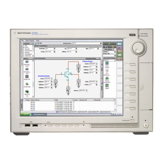
Page 36: To Use Application Test Mode
4. Change the measurement conditions at the Test Parameters field. The following example changes the voltage sweep output. a. Set VgStart to 0 V and VgStep to 0.2 V. b. Set VsubsStep to -1.0 V. 1- 12 Keysight B1500A User’s Guide, Ed ition 14... - Page 37 You can execute the test without modifications. Also you can create your own test setup/definition by making any changes. All furnished test definitions are just sample. Keysight Technologies is NOT LIABLE for any damages caused by the samples.
-
Page 38: To Use Classic Test Mode
To enter the value, use the USB keyboard or the screen/numeric keyboard opened by clicking the right button of the entry field. Figure 1-7 Display Example of I/V Sweep Channel Setup Screen 1- 14 Keysight B1500A User’s Guide, Ed ition 14... - Page 39 10 mV No of Step Compliance 100 mA Pwr Comp Sweep status CONTINUE AT ANY Table 1-6 I/V Sweep Display Setup Name Sharing Scale (None) Linear (None) Linear -1 pA 1 pA Keysight B1500A User’s Guide, Ed ition 14 1- 15...
-
Page 40: To Perform Measurement
Result Editor appears on the lower area of the screen when the measurement is completed. See “To Use Test Result Editor” on page 1-17. Figure 1-8 Display Example of Data Display Window 1- 16 Keysight B1500A User’s Guide, Ed ition 14... -
Page 41: To Use Test Result Editor
You can enter characters into this field. The characters will be recorded as the Remarks value of the test result record. • OK button Applies the setup on the Test Result Editor, and closes this dialog box. Keysight B1500A User’s Guide, Ed ition 14 1- 17... -
Page 42: To Use Analysis Tools
Figure 1-8. You can read position of the marker and the active cursor, and interrupt and gradient of the active line. Figure 1-9 Display Example of Analysis Tools 1- 18 Keysight B1500A User’s Guide, Ed ition 14... -
Page 43: Introduction
Introduction... - Page 44 Introduction This chapter describes the basic functions and features of Keysight B1500A Semiconductor Device Analyzer, and consists of the following sections: • “Overview” • “Front View” • “Rear View” • “Measurement Modules” Application Library NOTE Keysight B1500A has installed Keysight EasyEXPERT software as the user interface.
-
Page 45: Overview
Windows environment. You can analyze a measurement result characteristics graph for example by using several tools such as markers, cursors, and lines. Also, in the GPIB remote control mode, you can control the B1500A from an external computer by using Keysight FLEX command set that is the common language for Keysight semiconductor DC measurement instruments. - Page 46 High voltage semiconductor pulse generator unit module. Occupies one slot. Up to five modules can be installed in one mainframe. One module provides two output channels. Needs Keysight 16440A (B1500A-A04) and 16445A to perform automatic switching of the measurement resource connected to the DUT.
- Page 47 (two types), blank PTFE board, and connection wires for device connection. • Keysight 16445A selector adapter Used to connect the 16440A selector (B1500A-A04) to the B1500A. Two selectors can be connected. • Keysight E5288A ASU Atto sense and switch unit (ASU).
-
Page 48: Keysight Easyexpert Software
Keysight EasyEXPERT Software Keysight EasyEXPERT software is a specially-designed Windows application program for controlling Keysight B1500A. The EasyEXPERT provides the easy and effective measurement and analysis environment with intuitive graphical user interface (GUI), touch screen LCD panel, keyboard, and mouse. Some of the functions are listed below. - Page 49 • Direct Control The Direct Control test mode is used to control the measurement modules directly by using the B1500A GPIB control commands and perform measurement. For the control commands, see “Programming Guide”. Tracer Test Curve tracer test mode. This test allows you to perform the high speed I-V measurement on one screen.
-
Page 50: Front View
NOTE When turning the B1500A on Open the measurement terminals at the device side when turning the B1500A on. Also disconnect the device from the measurement terminals and open the measurement terminals after the measurement. If you leave the connection with the device, the device may be damaged by unexpected operations or charge-up of measurement cables. - Page 51 Works on Keysight EasyEXPERT environment. Rotating the knob moves the marker on the graph window, or increases/decreases/changes the value in the active entry field. Pressing the knob sets or enters the value. Keysight B1500A User’s Guide, Ed ition 14 2- 9...
- Page 52 DVD-ROM drive. 12. Touch Panel Off key Works on the execution environment of EasyEXPERT software. Enables or disables the touch screen operation. The green LED lights when the touch screen is disabled. 2- 10 Keysight B1500A User’s Guide, Ed ition 14...
-
Page 53: Rear View
Introduction Rear View Rear View This section describes the rear view of Keysight B1500A. 1. Serial number You need this serial number when using Keysight Technologies telephone assistance program. 2. LED status indicator For troubleshooting. Followings are some examples. •... - Page 54 5. Module slot Ten slots are available for installing the modules. Several kinds of module can be installed in the B1500A. However, the allowable number to install is different by the module type. See “Measurement Modules” on page 2-17.
- Page 55 VGA connector. For an external display. Signal to the built-in LCD is also applied to this terminal. For the B1500A manufactured before the video output terminal is supported, it is mounted on the position “14a” by upgrading the mainframe. Keysight B1500A User’s Guide, Ed ition 14...
- Page 56 SPGU at the lowest position. And the following PG numbers are assigned to the outputs of the upper SPGUs in sequence. Use the PG number label furnished with the B1500A or equivalent to identify the SPGU channel number. 2- 14...
- Page 57 SMU1 is assigned to the SMU at the lowest position. And the following SMU numbers are assigned to the upper SMUs in sequence. Use the SMU number label furnished with the B1500A or equivalent to identify the SMU number.
- Page 58 Use a three-conductor AC power cable to connect the instrument to an electrical ground (safety ground). • If you do not use the B1500A-A5F/16442A/B test fixture, you must install and connect an interlock circuit that opens the Interlock terminal when the shielding box access door is opened.
-
Page 59: Measurement Modules
GPIB remote mode. See Keysight B1530A User’s Guide for using the WGFMU. GNDU - Ground Unit Keysight B1500A is equipped with the ground unit (GNDU). The GNDU is a 0 V constant voltage source, and used for the reference of measurement ground. Also the GNDU can sink up to ±... -
Page 60: About Smu
When the SMU applies voltage, you can specify current compliance. When the SMU applies current, you can specify voltage compliance. For details about the compliance, see Keysight EasyEXPERT User’s Guide. 2- 18 Keysight B1500A User’s Guide, Ed ition 14... -
Page 61: Hpsmu - High Power Smu
Maximum voltage, current, output power: ± 200 V, ± 1 A, 20 W • Minimum range: 2 V, 1 nA • Output/measurement value and resolution: see Table 2-1 Table 2-4. Figure 2-3 HPSMU Output and Measurement Ranges Current (mA) 1000 Voltage (V) 1000 Keysight B1500A User’s Guide, Ed ition 14 2- 19... - Page 62 50 mA < |I| 125 mA 50 A ± 100 V 125 mA < |I| 500 mA 50 A ± 40 V 500 mA < |I| 1 A 50 A ± 20 V 2- 20 Keysight B1500A User’s Guide, Ed ition 14...
- Page 63 0 |I| 1 A 50 A 1 A a. This column is applied to the auto ranging or the limited auto ranging. For fixed ranging, maximum measurement value is Range column value. Keysight B1500A User’s Guide, Ed ition 14 2- 21...
-
Page 64: Mpsmu - Medium Power Smu
MPSMU Output and Measurement Ranges Current (mA) Voltage (V) NOTE The E5288A Atto Sense and Switch Unit (ASU) can be connected to the B1511B MPSMU, but it cannot be connected to the B1511A MPSMU. 2- 22 Keysight B1500A User’s Guide, Ed ition 14... - Page 65 20 mA < |I| 50 mA 5 A ± 40 V 50 mA < |I| 100 mA 5 A ± 20 V a. For B1511B MPSMU. Available when the ASU is used. Keysight B1500A User’s Guide, Ed ition 14 2- 23...
- Page 66 This column is applied to the auto ranging or the limited auto ranging. For fixed ranging, maximum measurement value is Range column value. b. For B1511B MPSMU. Available when the ASU is used. 2- 24 Keysight B1500A User’s Guide, Ed ition 14...
- Page 67 1 pA range, set the 1 pA fixed range or the 1 pA limited auto ranging. The B1500A automatically performs the compensation of the data measured by the 1 pA range and returns the compensated data. You can use either the pre-stored offset data or the pre-measured offset data.
-
Page 68: Mcsmu - Medium Current Smu
Minimum pulse width: 10 s • • Output/measurement value and resolution: see Table 2-9 Table 2-10. Figure 2-5 MCSMU Output and Measurement Ranges Current (A) Pulse mode only Voltage (V) Pulse mode only 2- 26 Keysight B1500A User’s Guide, Ed ition 14... - Page 69 0 |I| 115 mA 0 |I| 1 A 1 A ± 50 mA a. For pulse. b. For pulse. Maximum pulse width and duty cycle are 100 ms and 5 % respectively. Keysight B1500A User’s Guide, Ed ition 14 2- 27...
-
Page 70: Hrsmu - High Resolution Smu
Minimum range: 0.5 V, 10 pA (1 pA when the E5288A ASU is used) • Output/measurement value and resolution: see Table 2-11 Table 2-14. Figure 2-6 HRSMU Output and Measurement Ranges Current (mA) Voltage (V) 2- 28 Keysight B1500A User’s Guide, Ed ition 14... - Page 71 20 mA < |I| 50 mA 5 A ± 40 V 50 mA < |I| 100 mA 5 A ± 20 V a. Available when the ASU is used. Keysight B1500A User’s Guide, Ed ition 14 2- 29...
- Page 72 This column is applied to the auto ranging or the limited auto ranging. For fixed ranging, maximum measurement value is Range column value. b. Available when the ASU is used. 2- 30 Keysight B1500A User’s Guide, Ed ition 14...
- Page 73 1 pA range, set the 1 pA fixed range or the 1 pA limited auto ranging. The B1500A automatically performs the compensation of the data measured by the 1 pA range and returns the compensated data. You can use either the pre-stored offset data or the pre-measured offset data.
-
Page 74: Mfcmu - Multi Frequency Cmu
Use these information to decide the measurement range. Impedance Z is calculated by the following formula. Z = 1 / (2 f C) where f is frequency (Hz) and C is capacitance (F). 2- 32 Keysight B1500A User’s Guide, Ed ition 14... - Page 75 Q (quality factor) Rp (parallel resistance, ) Lp (parallel inductance, H) Rs (series resistance, ) Ls (series inductance, H) Ls (series inductance, H) D (dissipation factor) Ls (series inductance, H) Q (quality factor) Keysight B1500A User’s Guide, Ed ition 14 2- 33...
- Page 76 100 m 10 m 10 F 100 F 1 mF 10 mF range 100 mF 100 n 10 n 1 kHz 10 kHz 100 kHz 1 MHz 5 MHz Frequency f 2- 34 Keysight B1500A User’s Guide, Ed ition 14...
-
Page 77: Hvspgu - High Voltage Spgu
Automatic voltage level adjustment by specifying load impedance of DUT Figure 2-8 SPGU Simplified Circuit Diagram Pulse switch Pulse switch Output 1 Output 2 PG 2-level PG 2-level or 3-level or 3-level ALWG ALWG Keysight B1500A User’s Guide, Ed ition 14 2- 35... -
Page 78: Wgfmu - Waveform Generator/Fast Measurement Unit
Output level: 0 to -10 V, 0 to 10 V, or -5 V to 5 V Figure 2-9 WGFMU Simplified Circuit Diagram PG mode PG mode RSU output RSU output ALWG ALWG Fast IV mode Fast IV mode 2- 36 Keysight B1500A User’s Guide, Ed ition 14... -
Page 79: Installation
Installation... - Page 80 Installation This chapter describes how to install Keysight B1500A and accessories. • “Requirements” • “Inspection and Installation” • “Installing Accessories” • “Mounting Connectors” • “Connecting Measurement Devices” • “Capacitance Compensation When Using Switching Matrix” • “Maintenance” • “About Plug-in Modules”...
- Page 81 Use a three-conductor AC power cable to connect the instrument to an electrical ground (safety ground). • If you do not use the B1500A-A5F/16442A/B test fixture, you must install and connect an interlock circuit that opens the Interlock terminal when the shielding box access door is opened.
-
Page 82: Requirements
This instrument is specified to store/ship within the following environmental conditions: -20 C to 60 C Temperature: Humidity: 10 % to 90 % RH, non-condensing Altitude: 0 to 4,600 m (15,092 ft.) 3- 4 Keysight B1500A User’s Guide, Ed ition 14... -
Page 83: Installation Requirements
Keysight Sales and Support Office. The AC input on the back of your instrument is a universal AC input. It accepts nominal line voltages in the range of 100 to 240 VAC. Keysight B1500A User’s Guide, Ed ition 14 3- 5... - Page 84 PN: 8120-8376 • PN: 8121-0564 Option 931 Option 932 • Plug: CNS 10917-2, • Plug: CS 0017, 125 V, 10 A 250 V, 10 A • PN: 8121-1635 • PN: 8121-1638 3- 6 Keysight B1500A User’s Guide, Ed ition 14...
-
Page 85: Inspection And Installation
• water marks If you suspect any damage, notify your local Keysight Technologies sales or service office. 2. When you open the boxes that contain the instrument and accessories, check the components against the contents lists attached to the boxes. -
Page 86: To Perform Initial Setup
Set the system display language to English. The language must be English. If you set another language, you must perform the system recovery of the B1500A. See Keysight EasyEXPERT User’s Guide for the system recovery. b. Set Country or region, Time and currency, and Keyboard layout. -
Page 87: To Change Windows Logon Setting
To perform recovery, see Keysight EasyEXPERT User’s Guide. To Change Windows Logon Setting Keysight B1500A initially enables Windows automatic logon. If you want to change this setting, select All Programs > Control Auto Logon from the Start menu. Control Auto Logon is displayed on the browser. Then click one of the following buttons on the browser and follow the setup script. -
Page 88: To Change Gpib Address
6. Click the OK button on Keysight 82350 PCI GPIB Interface - GPIB0 window. 7. If the Reboot Required dialog box is displayed, click the Reboot Now button, and reboot the instrument. 3- 10 Keysight B1500A User’s Guide, Ed ition 14... -
Page 89: To Enable System Controller
To Disable System Controller NOTE If the B1500A is the system controller, you cannot control the B1500A by using an external computer. To disable the system controller, change the steps 4 and 5 for setting the GPIB Address value to not 21 and removing the check from the System Controller box, and perform the procedure to the step 8. -
Page 90: Installing Accessories
1 A. CAUTION Never connect the Guard terminal to any output, including circuit common, chassis ground, or any other guard terminal. Doing so will damage the SMU. 3- 12 Keysight B1500A User’s Guide, Ed ition 14... -
Page 91: To Connect 16442B Test Fixture (B1500A-A5F)
To Connect 16442B Test Fixture (B1500A-A5F) See this section if you use Keysight 16442B test fixture (B1500A-A5F). This section describes how to set up the 16442B and how to connect the B1500A to the 16442B. To Set up 16442B (B1500A-A5F) You can stabilize the 16442B (B1500A-A5F) as shown in the figure below. - Page 92 Hcur and Hpot terminals together and the Lcur and Lpot terminals together at the socket module inputs. It is ok to leave open the ground wire extended from the CMU cable. 3- 14 Keysight B1500A User’s Guide, Ed ition 14...
-
Page 93: To Connect Connector Plate
Triax connectors/BNC connectors. Use the cables shown in Table 3-4 to connect from the B1500A connectors to the connector plate’s relative connectors. For the cable connections from the connector plate to the DUT interface such as manipulator and probe card, see “Mounting... - Page 94 Hpot terminals together and the Lcur and Lpot terminals together on the DUT interface. See Figure 3-21. It is ok to leave open the ground wire extended from the CMU cable. 3- 16 Keysight B1500A User’s Guide, Ed ition 14...
-
Page 95: To Connect Asu
Installing Accessories To Connect ASU Keysight E5288A Atto Sense and Switch Unit (ASU) adds the following functions to the B1500A. To use the ASU, it must be connected to the SMU which is connected together when the calibration is performed. •... - Page 96 The specifications are satisfied and guaranteed in this condition only. So confirm the serial number of the ASU and connect it to the dedicated SMU properly. See Keysight EasyEXPERT User’s Guide to confirm the serial number. 3- 18 Keysight B1500A User’s Guide, Ed ition 14...
- Page 97 CMU Return terminals of the ASU #1 and ASU #2 together. About ASU output cables NOTE To perform capacitance measurements accurately, the cable length between DUT and the ASU output must be as short as possible. Keysight B1500A User’s Guide, Ed ition 14 3- 19...
- Page 98 AUX 1. Turn the instrument off. 2. Connect the BNC cable from the ASU CMU-cur/AUX In terminal to the instrument. Prepare an adapter if the instrument’s input/output connector is not BNC. 3- 20 Keysight B1500A User’s Guide, Ed ition 14...
-
Page 99: To Connect Scuu/Gswu
Keysight N1301A-102 SCUU cable (if SCUU is not attached to the MFCMU) • Keysight N1301A-110 Magnet stand (if GSWU is used) • BNC cable, coaxial cable, manipulator, wire, and so on Keysight B1500A User’s Guide, Ed ition 14 3- 21... - Page 100 2. Turn the B1500A off. Figure 3-5 To Connect SCUU/GSWU SCUU To CMU Force1/CMUH (slot N) Guard Sense1 GSWU Force1 To SMU Sense2 (slot N-1) Sense1 Guard Force2 Force2/CMUL To SMU (slot N-2) Sense2 3- 22 Keysight B1500A User’s Guide, Ed ition 14...
- Page 101 To attach the SCUU to the B1500A: SCUU/GSWU 1 1. Attach the SCUU to the B1500A rear panel connectors for the MFCMU in the slot N and two SMUs in the slots N-1 and N-2 (N: integer, 3 to 10).
- Page 102 Stand will be useful for fixing the SCUU. 3. Attach the other end of the SCUU cable to the B1500A rear panel connectors for the MFCMU in the slot N and two SMUs in the slots N-1 and N-2 (N: integer, 3 to 10).
-
Page 103: To Connect Gndu Adapter
Circuit Common terminal respectively. 2. Push the adapter toward the B1500A. 3. Rotate the GNDU connector handle of the adapter to fix it to the B1500A. Use the following cables to extend the GNDU Force and Sense terminals. -
Page 104: To Connect Mcsmu Connection Box
16494A Triaxial cable, 2 ea. Voltage rating of terminal is indicated near connector on the Input or Output panel. The N1255A cannot be used for measurement of the IEC Measurement Category II, III, or IV. 3- 26 Keysight B1500A User’s Guide, Ed ition 14... - Page 105 If the switch is set to “Non-Kelvin”, do not extend the Sense output corresponding to it. Voltage on the Force line also appears on the Sense line. So, open the Sense connector on the Output panel. Keysight B1500A User’s Guide, Ed ition 14 3- 27...
- Page 106 Sense Common Sense Common Open the Sense terminal if the switch is set to Non-Kelvin. Circuit Common Circuit Common High Sense Low Sense Low Force High Force Circuit Common Circuit Common 3- 28 Keysight B1500A User’s Guide, Ed ition 14...
-
Page 107: Mounting Connectors
For safety, prepare and attach a shield cover to avoid touching the joints on the wiring side of connectors. And ground the cover. Wrap an insulator around the naked conductors of coaxial cable to avoid touching it. Keysight B1500A User’s Guide, Ed ition 14 3- 29... - Page 108 Dimensions of Connector Holes Kelvin Triaxial Connector (in mm) Triaxial Connector (in mm) 11.3 10.3 2 − 11.3 2 − M3 x 0.5 BNC Connector (in mm) Interlock Connector (in mm) 12.8 3- 30 Keysight B1500A User’s Guide, Ed ition 14...
-
Page 109: To Make An Interlock Circuit
Figure 3-11 Interlock Connector Pin Assignments Interlock switch Connector side Wiring side WARNING Potentially hazardous voltages may be present at the Force, Guard, and Sense terminals when the interlock terminals are shorted. Keysight B1500A User’s Guide, Ed ition 14 3- 31... - Page 110 3-11. If Keysight B1500A Interlock connector is connected to the interlock circuit, Keysight B1500A SMU cannot force more than ± 42 V when the door is open. When the door is closed, it can force more than ± 42 V.
- Page 111 Switch off 15.3 10.3 15.9 18.8 C OM 22.2 27.8 Units: mm Figure 3-14 Dimensions of the Interlock Switch (3101-3241) 10.2 27.5 10.9 Switch off Switch on 15.9 Units: mm 27.8 Keysight B1500A User’s Guide, Ed ition 14 3- 33...
-
Page 112: To Connect Gndu Output
Use Keysight 16493L GNDU cable to connect the GNDU to your connector plate or test fixture. Do not use the triaxial cable. The GNDU is rated for up to 4.2 A, while the maximum current rating of the triaxial cable is 1 A. 3- 34 Keysight B1500A User’s Guide, Ed ition 14... -
Page 113: To Connect Smu Output
(for Force/Sense signal) approx. 10 to 15 mm Outer conductor Insulator (clear) (for Guard signal) Conductive layer (black) WARNING Wrap an insulator around the naked conductors of coaxial cable to avoid touching it. Keysight B1500A User’s Guide, Ed ition 14 3- 35... - Page 114 To Minimize Leakage Current NOTE For the highly accurate current forcing and measurements, surround all force and sense lines by a guard as far as possible, and physically stable the cables with tape. 3- 36 Keysight B1500A User’s Guide, Ed ition 14...
- Page 115 ASU#1 CMU Return and the ASU#2 CMU Return. If the 4TP instrument is not used, you can ignore the CMH, CML, CMU Return, and the DUT1 high and low terminals. Keysight B1500A User’s Guide, Ed ition 14 3- 37...
- Page 116 ASU#1 CMU Return and the ASU#2 CMU Return. If the 4TP instrument is not used, you can ignore the CMH, CML, CMU Return, and the DUT1 high and low terminals shown above. 3- 38 Keysight B1500A User’s Guide, Ed ition 14...
- Page 117 CMU high, and the other one is used for the CMU low. For the accurate impedance measurements, wires must be connected to the GSWU from the CMH guard and the CML guard as near as possible to the DUT. Keysight B1500A User’s Guide, Ed ition 14 3- 39...
- Page 118 CMU high signal, and the other one is used for the CMU low signal. For the accurate impedance measurements, wires must be connected to the GSWU from the CMH guard and the CML guard as near as possible to the DUT. 3- 40 Keysight B1500A User’s Guide, Ed ition 14...
-
Page 119: To Connect Mcsmu Output
To simplify the connections, omit the wiring of the Common. For the non-Kelvin connection, use the High Force and the Low Force only. Omit the wiring of the High Sense and the Low Sense. Keysight B1500A User’s Guide, Ed ition 14 3- 41... -
Page 120: To Connect Mfcmu Output
The Hcur/Hpot/Lcur/Lpot lines should be connected to the DUT as shown above. Use a 50 coaxial cable (Keysight part number: 8120-0367) for the Hcur/Hpot/Lcur/Lpot lines connection. Use a wire for the guard connection. 3- 42 Keysight B1500A User’s Guide, Ed ition 14... -
Page 121: Connecting Measurement Devices
Connecting Measurement Devices This section describes how to connect device under test (DUT) to the 16442B test fixture (B1500A-A5F), and how to connect cables to the connector plate. If you use a wafer prober, see wafer prober manuals. Note that you must set the module output off when connecting or disconnecting DUTs. -
Page 122: Using Test Fixture
When you touch the DUT after measurement, devise a countermeasure of residual charge and heat to prevent electrical shock and burn. Use glove and any tool. Also have enough time for discharge and radiation. 3- 44 Keysight B1500A User’s Guide, Ed ition 14... - Page 123 Sense Guard Guard Guard Guard Guard Guard Drain Gate Substrate Source To cancel the effects of the residual resistance, test leads must be connected as close as possible to the DUT. Keysight B1500A User’s Guide, Ed ition 14 3- 45...
-
Page 124: Using Connector Plate
For safety, prepare and attach a shield cover to the connector plate to avoid touching the joints on the wiring side of connectors. And ground the cover. Wrap an insulator around the naked conductors of coaxial cable to avoid touching it. 3- 46 Keysight B1500A User’s Guide, Ed ition 14... - Page 125 Therefore, the current measured by SMU is same as current at measurement point because no current is leaked. Force Guard Buffer Keysight B1500A User’s Guide, Ed ition 14 3- 47...
- Page 126 For safety, prepare and attach a shield cover to the connector plate to avoid touching the joints on the wiring side of connectors. And ground the cover. Wrap an insulator around the naked conductors of coaxial cable to avoid touching it. 3- 48 Keysight B1500A User’s Guide, Ed ition 14...
- Page 127 So output error is not significant if the sense line wiring has a residual resistance of 10 or less. Therefore, the specified voltage appears at the sense point (point where sense line contacts force line) Keysight B1500A User’s Guide, Ed ition 14 3- 49...
-
Page 128: Capacitance Compensation When Using Switching Matrix
B2200A/B2201A/E5250A switching matrix, Keysight B1500A measures the capacitance/ conductance of the path including a DUT (device under test), matrix switches, extension cables and so on. So, the data measured by the B1500A is far from the DUT’s capacitance/conductance. Keysight EasyEXPERT provides the functions used to compensate the data measured in the environments described in “Required Conditions”... -
Page 129: Required Conditions
You can also use another type of triaxial cable, coaxial cable, or combination of these. To approximate the capacitance/conductance of the DUT, you need to obtain the appropriate compensation coefficients for your measurement environment, and create your compensation data file. See Figure 3-22. Keysight B1500A User’s Guide, Ed ition 14 3- 51... - Page 130 Extended triaxial B2210A outputs or (C3H, DATA07, need update) cables B2211A outputs or (C3L, DATA08, need update) with connector plate E5252A outputs (C2H, DATA05, need update) (C2L, DATA06, need update) 3- 52 Keysight B1500A User’s Guide, Ed ition 14...
-
Page 131: To Create Compensation Data File
3-9. Do not modify the other lines. NOTE EasyEXPERT provides the template of the compensation data file for the B2200A/B2201A. See Table 3-11. Select and use the template suitable for your measurement environment. Keysight B1500A User’s Guide, Ed ition 14 3- 53... - Page 132 Figure 3-22. (DATA08) For the connector plate, the coaxial cable with positioner will be the appropriate path. For Keysight B2220A probe card interface, the probe card will be the appropriate path. 3- 54 Keysight B1500A User’s Guide, Ed ition 14...
- Page 133 User Compensation Data File field of the Extended Configuration dialog box, and execute the measurement. Before starting measurement, perform the CMU calibration. For details, see Keysight EasyEXPERT User’s Guide. Keysight B1500A User’s Guide, Ed ition 14 3- 55...
- Page 134 L between A and C. Figure 3-23 Compensation Coefficient Measurement Terminals of Extended Cables GUARD (C) GROUND (E) GROUND (F) GUARD (D) Insulator Triaxial Cable FORCE or SENSE (A) FORCE or SENSE (B) 3- 56 Keysight B1500A User’s Guide, Ed ition 14...
- Page 135 16494C-005 a. <path>: \Program Files\Agilent\B1500\EasyEXPERT\B220xA\ccdata b. Model number of the cable connected between the switch module and the DUT interface. c. Keysight B2220A probe card interface or Keysight 16495F/G connector plate. Keysight B1500A User’s Guide, Ed ition 14 3- 57...
-
Page 136: Maintenance
Interlock function limits the maximum output voltage to ± 42 V when the measurement terminal is touchable. For safety, this function must be checked before using the B1500A after power on at least once a day by performing the diagnostics. Calibration Calibration and adjustments must be performed periodically so that the instruments satisfy the specifications, and keep a good condition. -
Page 137: About Plug-In Modules
For example, if the module configuration is two HPSMU, two MPSMU, and one CMU, the B1500A will be shipped with the HPSMUs of the slots 1 to 4, the MPSMUs of the slots 5 to 6, the CMU of the slot 7, and the blank panels of the slots 8 to 10. -
Page 138: To Interconnect Spgus
Connect the Ref Out/In, Sync Out/In, and Trig Out terminals to the specified terminal properly. Connecting to the other terminal may result in damage to the SPGU. NOTE The B1500A does not support the synchronized operation between SPGU and WGFMU. 3- 60 Keysight B1500A User’s Guide, Ed ition 14... -
Page 139: To Interconnect Wgfmus
Connect the Sync Out/In, and Trig Out terminals to the specified terminal properly. Connecting to the other terminal may result in damage to the WGFMU. NOTE The B1500A does not support the synchronized operation between SPGU and WGFMU. Keysight B1500A User’s Guide, Ed ition 14... -
Page 140: About Module Installation
Contact Keysight Technologies to upgrade the B1500A. Module locations after servicing NOTE After the module installation, upgrade, and so on, the B1500A will be returned with the module configuration decided by the rule shown in Table 3-12. If you want to change the module locations, consult the service personnel before servicing. -
Page 141: Specifications
Specifications... - Page 142 Keysight B1500A Semiconductor Device Analyzer and its associated modules. The specifications are the standards against which the B1500A and its associated modules are tested. When the B1500A and any of its associated modules are shipped from the factory, they meet the specifications. The “supplemental” information and “typical”...
-
Page 143: Hardware
10. WGFMU load capacitance: 25 pF or less NOTE Keysight Technologies is responsible for removing, installing, and replacing the B1500A modules. Contact your nearest Keysight Technologies to install and calibrate the B1500A modules. Keysight B1500A User’s Guide, Ed ition 14... - Page 144 Specifications Hardware Supported Plug-in Modules The B1500A supports ten slots for the following plug-in modules. B1510A High power source/monitor unit (HPSMU). • Slots occupied: 2 • Range up to 200 V/1 A with 4-quadrant operation Minimum measurement resolution 10 fA/2 V •...
- Page 145 • Flexible arbitrary waveform generation with 10 ns resolution (arbitrary linear waveform generation function) • Two channels per module B1530A Waveform generator / fast measurement unit (WGFMU). • Slots occupied: 1 Keysight B1500A User’s Guide, Ed ition 14 4- 5...
- Page 146 No load line effect accurate pulsed IV measurement by dynamic SMU technology Maximum Module Configuration The B1500A can contain any combination of the following module. Then the total power consumption of all SMU modules cannot exceed 84 W. • Up to 10 MPSMU •...
- Page 147 Force < 0.7 (1.6 A < Is 2.0 A) < 0.35 (2.0 A < Is 4.2 A) where Is is the current being sunk by the GNDU. Keysight B1500A User’s Guide, Ed ition 14 4- 7...
-
Page 148: Mpsmu
Io 20 20 < Vc 40 Io 40 40 < Vc 100 Io 100 a. Vc is the voltage compliance setting. b. Io is the output current. 4- 8 Keysight B1500A User’s Guide, Ed ition 14... - Page 149 Not applicable for the MPSMU without ASU. d. 100 V (Io 20 mA), 40 V (20 mA < Io 50 mA), 20 V (50 mA < Io), Io is the output current. Keysight B1500A User’s Guide, Ed ition 14 4- 9...
- Page 150 Not applicable for the MPSMU without ASU. d. 100 V (Io 20 mA), 40 V (20 mA < Io 50 mA), 20 V (50 mA < Io), Io is the output current. 4- 10 Keysight B1500A User’s Guide, Ed ition 14...
- Page 151 SMU which is connected together when the calibration is performed. Confirm the serial number of the ASU, and connect it properly. Connection path control NOTE Disable source output of the instruments connected to the ASU inputs before controlling the ASU connection path. Keysight B1500A User’s Guide, Ed ition 14 4- 11...
-
Page 152: Hpsmu
Io 40 40 < Vc 100 Io 100 100 < Vc 200 Io 200 a. Vc is the voltage compliance setting. b. Io is the output current. 4- 12 Keysight B1500A User’s Guide, Ed ition 14... - Page 153 200 V (Io 50 mA), 100 V (50 mA < Io 125 mA), 40 V (125 mA < Io 500 mA), 20 V (500 mA < Io 1 A), Io is the output current. Keysight B1500A User’s Guide, Ed ition 14 4- 13...
- Page 154 200 V (Io 50 mA), 100 V (50 mA < Io 125 mA), 40 V (125 mA < Io 500 mA), 20 V (500 mA < Io 1 A), Io is the output current. 4- 14 Keysight B1500A User’s Guide, Ed ition 14...
-
Page 155: Mcsmu
Io 40 0.2 < Vc 2 Io 40 2 < Vc 40 Io 40 a. Vc is the voltage compliance setting. b. Io is the output current. Keysight B1500A User’s Guide, Ed ition 14 4- 15... - Page 156 ±(% of output/measured value + fixed offset + proportional offset), Vo is the output voltage in V. b. Pulse mode only. The maximum value of the base current during pulsing is ±50 mA. 4- 16 Keysight B1500A User’s Guide, Ed ition 14...
- Page 157 Period: 5 ms to 5 s, 100 s resolution • Period Width+2 ms (when Width 100 ms) Period Width+10 ms (when Width > 100 ms) • Delay: 0 s Keysight B1500A User’s Guide, Ed ition 14 4- 17...
- Page 158 Voltage and current measurement accuracy can be affected by induced RF field noise strengths greater than 3Vrms in the frequency range of 150 kHz to 80 MHz. The extent of this effect depends upon how the instrument is positioned and shielded. 4- 18 Keysight B1500A User’s Guide, Ed ition 14...
- Page 159 Voltage measurement input resistance For HPSMU, MPSMU, HRSMU: 10 For MCSMU: 10 • Current source output resistance For HPSMU, MPSMU, HRSMU: 10 For MCSMU: 10 Keysight B1500A User’s Guide, Ed ition 14 4- 19...
- Page 160 Voltage source: 0.01 % of V range (rms.) Current source: 0.1 % of I range (rms.) For MCSMU Voltage/Current source: 200 mV (0 to peak) max Condition: filter ON for HPSMU, MPSMU, and HRSMU 4- 20 Keysight B1500A User’s Guide, Ed ition 14...
- Page 161 ± 4.2 mV (HRSMU/MPSMU with ASU, Iout 100 A) • Maximum slew rate 0.2 V/s (HPSMU, MPSMU, HRSMU) 1 V/s (MCSMU) • Maximum DC floating voltage ± 200 V DC between low force and common (MCSMU) Keysight B1500A User’s Guide, Ed ition 14 4- 21...
-
Page 162: Mfcmu
± (10.0 % of reading + 1 mVrms) at the measurement port of the MFCMU ± (15.0 % of reading + 1 mVrms) at the measurement port of the MFCMU cable (1.5 m or 3.0 m) 4- 22 Keysight B1500A User’s Guide, Ed ition 14... - Page 163 Available sweep parameters: DC bias voltage, oscillator level, frequency • Sweep type: linear, log • Sweep mode: single, double • Sweep direction: up, down • Number of measurement points: maximum 1001 Keysight B1500A User’s Guide, Ed ition 14 4- 23...
- Page 164 Table 4-13. Calculation example of the measurement accuracy is also shown in Table 4-14. Specification conditions: Temperature: 23 C ± 5 C • • Integration time: 1 PLC or 16 PLC 4- 24 Keysight B1500A User’s Guide, Ed ition 14...
- Page 165 1k f 200k 1(125/Vosc-0.5) 0.095 200k < f 1M 2(125/Vosc-0.5) 0.095 1M < f 2M 2(125/Vosc-0.5) 0.28 2M < f 20(125/Vosc-0.5) 30.0 0.28 Vosc is oscillator level in mV. Keysight B1500A User’s Guide, Ed ition 14 4- 25...
- Page 166 ± 619 nS a. The calculation examples are specified under the conditions Dx = 0.1, 1 PLC integration time, 30 mVrms test signal level, and at four-terminal pair port of MFCMU. 4- 26 Keysight B1500A User’s Guide, Ed ition 14...
- Page 167 LED: SMU/CMU output status indicator • Docking mode Direct and indirect mode • GSWU • Input Control port: for SCUU Mini pin plug port: Guard1 and Guard2 • Output LED: Connection status indicator Keysight B1500A User’s Guide, Ed ition 14 4- 27...
- Page 168 Range: 0 to ± 25 V Resolution: 1 mV Additional errors (for CMU bias): ± 100 V (open load) • DC voltage bias (SMU bias) Range: 0 to ± 100 V Resolution: 5 mV 4- 28 Keysight B1500A User’s Guide, Ed ition 14...
- Page 169 DUT side cable end. Specification conditions: Temperature: 23 C ± 5 C • • Integration time: 1 PLC or 16 PLC Keysight B1500A User’s Guide, Ed ition 14 4- 29...
-
Page 170: Hv-Spgu
> 10 s) • Pulse range and pulse parameter: See Table 4-15. • Pulse/DC output voltage and accuracy: See Table 4-16. Figure 4-1 SPGU pulse setup parameters Tperiod Tdelay Twidth Vpeak Vamp Vbase 4- 30 Keysight B1500A User’s Guide, Ed ition 14... - Page 171 The time from 10 % to 90 % of Vamp which is the amplitude of output pulse. d. The time it takes the open state relay to open or close. Keysight B1500A User’s Guide, Ed ition 14 4- 31...
- Page 172 Output complex waveform per one channel of HV-SPGU • Define multi-level pulse and multi-pulse waveform including open state pulse with ALWG GUI editor • Sequential pulse waveform from user-defined pulse waveform • 1024 points per one channel 4- 32 Keysight B1500A User’s Guide, Ed ition 14...
- Page 173 10.0 V 400 ns 10.0 V 450 ns 0.0 V 500 ns 500 ns 0.0 V Figure 4-3 ALWG complex waveform example Pattern1 x 1 Pattern2 x 5 Pattern3 x 1 Keysight B1500A User’s Guide, Ed ition 14 4- 33...
- Page 174 The PGU port on channel 1 provides a “PGU OPEN” function, which can disconnect the PGU by opening a semiconductor relay. Keysight B1500A and 16445A are required to use the selector. The following specifications data is specified at 23 C ± 5 C (73 F ± 9 F) and 50 % relative humidity.
- Page 175 • SMU path • Maximum voltage: ± 25 V • Maximum current: ± 100 mA • V Monitor terminal • Connector: BNC Source impedance: 50 (nominal), at DC output • Keysight B1500A User’s Guide, Ed ition 14 4- 35...
- Page 176 Note: The maximum number of installable RSUs for a given prober depends upon the available space. Please contact your local sales representative for details on connecting and mounting the WGFMU and RSU. 4- 36 Keysight B1500A User’s Guide, Ed ition 14...
- Page 177 -10 V to 0 V, +10 V 1 mA, 10 mA V measure 0 V to +10 V SMU pass Measurement Maximum Maximum through using SMU ± 25 V ± 100 mA Keysight B1500A User’s Guide, Ed ition 14 4- 37...
- Page 178 PG mode, 50 load, T 24 ns and T rise fall f. PG mode, 50 load, pulse period 100 ns g. PG mode, 50 load, pulse width 50 ns 4- 38 Keysight B1500A User’s Guide, Ed ition 14...
- Page 179 5 ns, or 10 ns to 1 s with 10 ns resolution Averaging time 10 ns to 20 ms with 10 ns resolution Hardware memory About 4 M data points/channel (typical) Keysight B1500A User’s Guide, Ed ition 14 4- 39...
- Page 180 20 pF. Voltage is applied to the DUT by a channel of WGFMU/RSU in Fast IV mode and in the 10 mA range, and current measurement is performed by another channel at 0 V in Fast IV mode. 4- 40 Keysight B1500A User’s Guide, Ed ition 14...
- Page 181 RSU and the DUT is 20 pF. Voltage is applied to the DUT by a channel of WGFMU/RSU, and voltage measurement is performed by the same channel. (PG mode for 5 V, Fast IV mode for 10 V) Keysight B1500A User’s Guide, Ed ition 14 4- 41...
-
Page 182: Easyexpert Software
You can easily edit and customize the furnished application tests to fit your specific needs. The following table shows a part of tests included in the library. They are subject to change without notice. 4- 42 Keysight B1500A User’s Guide, Ed ition 14... - Page 183 • Sampling points: 2000 Sa Sampling duration: 22 s to 24 ms • • Marker function Data read-out for each channel Resolution: 2 s • Data saving Numeric: TXT/CSV/XMLSS Image: EMF/BMP/JPG/PNG Keysight B1500A User’s Guide, Ed ition 14 4- 43...
-
Page 184: Measurement Modes
Sweep direction: single or double Hold time: 0 to 655.35 s, 10 ms resolution Delay time: 0 to 65.535 s or 655.35 s for CV (AC level) sweep and C-f sweep, 100 s resolution 4- 44 Keysight B1500A User’s Guide, Ed ition 14... - Page 185 The function ceases as soon as these conditions end or when a measurement that does not use this function is started. Keysight B1500A User’s Guide, Ed ition 14 4- 45...
-
Page 186: Data Display
Measurement data and calculated user function data are listed in conjunction with sweep step number or time domain sampling step number. Up to 20 data sets can be displayed. • Data variable display Up to 20 user-defined parameters can be displayed. 4- 46 Keysight B1500A User’s Guide, Ed ition 14... - Page 187 ), u or (10 a (10 ), f (10 ), p (10 ), n (10 ), m (10 ), k (10 ), M (10 ), G ), T (10 ), P (10 Keysight B1500A User’s Guide, Ed ition 14 4- 47...
- Page 188 • Wafer prober control Scripts to perform chuck move/up/down and subsite move for major semi- automatic probers are furnished. The wafer prober control can be performed in the repeat measurement process. 4- 48 Keysight B1500A User’s Guide, Ed ition 14...
-
Page 189: Program And Interface Capabilities
Converts the EasyEXPERT test result data file (extension XTR or ZTR) to Keysight IC-CAP MDM file. Supports the data of the following classic tests. • I/V Sweep • Multi Channel I/V Sweep • C-V Sweep Keysight B1500A User’s Guide, Ed ition 14 4- 49... -
Page 190: Desktop Easyexpert Software
SMUC: 04.08 or later • Supported 4155/4156 functionality • I/V sweep • I/V-t sampling (except thinned out mode) • VSU/VMU (except differential voltage measurement using VMU) • PGU (41501B) • Switching matrix control 4- 50 Keysight B1500A User’s Guide, Ed ition 14... -
Page 191: General Specifications
• Dimensions B1500A: 420 mm (W) 330 mm (H) 575 mm (D) B1531A RSU: 45.2 mm (W) 70 mm (H) 82 mm (D) E5288A ASU: 132 mm (W) 88.5 mm (H) 50 mm (D) N1255A Connection box: 184.4 mm (W) ... - Page 192 B1517A: 1.2 kg B1520A: 1.5 kg B1525A: 1.3 kg B1530A: 1.3 kg B1531A: 0.13 kg E5288A: 0.5 kg N1255A: 0.7 kg N1301A-100: 0.8 kg N1301A-200: 0.1 kg 16440A: 1.1 kg 16445A: 1.0 kg 4- 52 Keysight B1500A User’s Guide, Ed ition 14...
- Page 193 Accessories and Options...
- Page 194 Then the GNDU cable must be used for extending the GNDU Force. And the triaxial cable must be used for the Sense. Cable length 1.5 m or 3.0 m is specified by the option B1500A-015 or B1500A-030. 5- 2...
- Page 195 Table 5-6 B1500A-A6J ANSI Z540 compliant calibration B1500A-ABA Paper manual set, English B1500A-ABJ Paper manual set, Japanese B1500A-DR1 Changing DVD-R drive to DVD-ROM drive B1500A-UK6 Commercial calibration certificate with test data Keysight B1500A User’s Guide, Ed ition 14 5- 3...
- Page 196 RSU cable, 2.4 m, between WGFMU and connector adapter RSU cable, 0.6 m, between RSU and connector adapter 16493R-801 connector adapter (female-female) 1. The option B1500A-A31 cannot be selected with the option B1500A-015. 5- 4 Keysight B1500A User’s Guide, Ed ition 14...
- Page 197 Connection wire, mini banana to mini clip 3/color Connection wire, mini banana to mini banana 3/color 1. Contains four types of the connection wire. There is three colors for each connection wire, black, red, and blue. Keysight B1500A User’s Guide, Ed ition 14 5- 5...
- Page 198 Socket module, 4-pin TO package 16442B-822 Socket module, 18-pin DIP package 16442B-823 Extra socket module, 28-pin DIP package 16442B-890 Extra accessory case 16444A Accessories for B1500A 16444A-001 USB keyboard 16444A-002 USB mouse 16444A-003 Stylus pen 5- 6 Keysight B1500A User’s Guide, Ed ition 14...
-
Page 199: Keysight B1500A User's Guide, Ed Ition
16493M-002 3 m length 16493N GNDU cable for B2200 Kelvin input 16493N-001 2 m length 16493P SPGU output connection cable (SMA to BNC) 16493P-001 1.5 m length 16493P-002 3 m length Keysight B1500A User’s Guide, Ed ition 14 5- 7... - Page 200 16494A-003 80 cm length 16494A-004 40 cm length 16494A-005 4 m length 16494B Kelvin triaxial cable (B1500 to E5250) 16494B-001 1.5 m length 16494B-002 3 m length 16494B-003 80 cm length 5- 8 Keysight B1500A User’s Guide, Ed ition 14...
- Page 201 B1525A Semiconductor Pulse Generator Unit module (SPGU) B1530A Waveform Generator/Fast Measurement Unit (WGFMU) B1530A-0KN Self-paced sample program learning kit B1531A Remote-sense and Switch Unit (RSU) B1542A Pulsed IV package for B1500A/EasyEXPERT Keysight B1500A User’s Guide, Ed ition 14 5- 9...
- Page 202 Accessories for CMU N1301A-100 SMU CMU Unify Unit (SCUU) N1301A-102 SCUU cable, 3 m N1301A-110 SCUU magnetic stand N1301A-200 Guard Switch Unit (GSWU) N1301A-201 GSWU cable, 1.5 m N1301A-202 GSWU cable, 3 m 5- 10 Keysight B1500A User’s Guide, Ed ition 14...
- Page 204 This information is subject to change without notice. © Keysight Technologies 2005-2014 Edition 14, August 2014 *B1500-90000* B1500-90000 www.keysight.com...
Need help?
Do you have a question about the B1500A and is the answer not in the manual?
Questions and answers