Sign In
Upload
Download
Table of Contents
Contents
Add to my manuals
Delete from my manuals
Share
URL of this page:
HTML Link:
Bookmark this page
Add
Manual will be automatically added to "My Manuals"
Print this page
×
Bookmark added
×
Added to my manuals
Manuals
Brands
Labcyte Manuals
Laboratory Equipment
Echo 520
User manual
Labcyte Echo 520 User Manual
Liquid handler
Hide thumbs
1
2
Table Of Contents
3
4
5
6
7
8
9
10
11
12
13
14
15
16
17
18
19
20
21
22
23
24
25
26
27
28
29
30
31
32
33
34
35
36
37
38
39
40
41
42
43
44
45
46
47
48
49
50
51
52
53
54
55
56
57
58
59
60
61
62
63
64
65
66
67
68
69
70
71
72
73
74
75
76
77
78
79
80
81
82
83
84
85
86
87
88
89
90
91
92
93
94
95
96
97
98
99
100
101
102
103
104
105
106
107
108
109
110
111
112
113
114
115
116
117
118
119
120
121
122
123
124
125
126
127
128
129
130
131
132
133
134
135
136
137
138
139
140
141
142
143
144
145
146
147
148
149
150
151
152
153
154
155
156
157
158
159
160
161
162
163
164
165
166
167
168
169
170
171
172
173
174
175
176
177
178
179
180
181
182
183
184
185
186
187
188
189
190
191
192
193
194
195
196
197
198
199
200
page
of
200
Go
/
200
Contents
Table of Contents
Troubleshooting
Bookmarks
Table of Contents
Table of Contents
Preface
Intended Audience
Safety Warnings and Precautions
Safety Notation Marks
Electrical Safety Warnings
Additional Safety Warnings
Safety Cautions
Emergency off Switch (EMO)
Laser Safety Warnings
Product Labels
Electrical Hazard
ETL Label
General Warning Label
Intellectual Property Label
Laser Safety Labels
Emergency off Label
Water System Maintenance Label
WEEE Label
Laser Safety Labels
Pinch Point Label
Product Label
High-Voltage Label
Using this Manual
What Is in this Manual
Who Should Read this Manual
Conventions Used in this Manual
Chapter 1 Introduction
Acoustic Droplet Ejection
How Does the Echo System Work
Will the Fluid Splash or Fall out
What Are the Echo Liquid Handler Features
Touchless" Fluid Transfers
Reliability
Ease of Use
System Integration Friendly
Low Maintenance Requirements
Cost Savings
High Accuracy, Precision, and Speed
Value-Added Quality Control
What Types of Liquid Transfer Are Supported
384-Plate to 384-Plate Liquid Transfer
384-Plate to 96-Plate Liquid Transfer
384-Plate to 1536-Plate Liquid Transfer
1536-Plate to 384-Plate Liquid Transfer
1536-Plate to 1536-Plate Liquid Transfer
What System Configurations Are Supported
Manual Operation
Echo Applications
Modular Workstation Operation
Small Cell Operation
Fully Automated Operation
Multi-Client Considerations
Chapter 2 Installation and Relocation
Pre-Installation Requirements
Site Requirements
Additional Components
Installation Overview
Software Installation
Install the Software
Uninstall the Echo Software
Upgrade the Echo Software
Instrument Relocation
Prepare the Echo Liquid Handler for a Move
Reinstall the Echo Liquid Handler after a Move
Chapter 3 System Description
System Overview
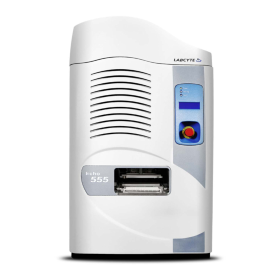
Front Panel
Back Panel
Component Description
Process Door
Source Plate Gripper Stage
Source Plate Insert
Destination Plate Gripper Stage
Status Indicator Lights
LCD Screen
Emergency off Switch
Anti-Static Bars
AC Power and Fuse Compartment
Coupling Fluid Bottle
Fluid Chiller
Fluidics Panel
Specifications
Physical
Mechanical
Environmental
Electrical
Client PC
Communications
Fluid Transfer
Supported Labware
Coupling Fluid
Chapter 4 Manual Operation
Startup/Shutdown
Turn on Echo Power
Launch Echo Software
Turn off Echo Power
Main Screen
Create Liquid Transfer Protocol
Add New Protocol
Run the Liquid Transfer Protocol
Prepare the Microplates
Start Liquid Transfer Run
Chapter 5 Echo Liquid Handler Software
Protocols Window
Create a Protocol
Edit an Existing Protocol Definition
Remove an Existing Protocol Definition
Run a Protocol
Labware Window
Plate Name Convention
Plate Specification Editor
Diagnostics Window
Device Control
Status Indicators
Diagnostic Procedures
Calibration Window
Motion Calibration
Power Calibration
Transducer Calibration
Advanced Window
Advanced Liquid Transfer Controls
Advanced Solvent Concentration (DMSO Only)
Advanced Echo Control
Status Window
Chapter 6 Maintenance and Service
Maintenance Schedule
Daily Maintenance
Echo Maintenance Alerts
Scheduled Maintenance
Maintenance Procedures
Maintenance Tools and Materials
Refill the Coupling Fluid Bottle
Clean and Refill the Coupling Fluid Bottle
Empty the Coupling Fluid Bottle
Replace the Water Filter
Clean the Anti-Static Bars
Replace the AC Power Fuse
Extended Non-Use and Storage
Maintenance During Extended Non-Use
Preparation for Storage
Chapter 7 Contact Information and Troubleshooting
Contact Information
Setup Problems
Maintenance Alerts
Appendix A. Acoustic Droplet Ejection Technology
ADE History
ADE and the Echo Liquid Handler
Source Microplate Survey
Fluid Transfer
Positioning the ADE Elements
Creating the Acoustic Pulse
Transferring the Droplet
Examples of Acoustic Droplet Ejection
Appendix B. Barcode Locations
Short Flange Height Microplates
Medium Flange Height Microplates
Appendix C. Chiller Information
Shipping Contents
Safety Warnings and Precautions
Chiller Setup and Operation
Setup
Operation
Troubleshooting
Advertisement
Quick Links
Download this manual
For Echo models: 520
550
555
Table of
Contents
Previous
Page
Next
Page
1
2
3
4
5
Advertisement
Table of Contents
Troubleshooting
Chapter 7 Contact Information and Troubleshooting
181
Troubleshooting
198
Need help?
Do you have a question about the Echo 520 and is the answer not in the manual?
Ask a question
Questions and answers
Related Manuals for Labcyte Echo 520
Laboratory Equipment labcyte Echo 525 User Manual
Rapid, acoustic liquid handler (171 pages)
Laboratory Equipment Labcyte Echo 550 User Manual
Liquid handler (200 pages)
Laboratory Equipment Labcyte Echo 555 User Manual
Liquid handler (200 pages)
Laboratory Equipment Labcyte Echo 650 Series Quick Start Manual
Liquid handler (14 pages)
Laboratory Equipment Labcyte Echo 655 Quick Start Manual
Liquid handler (14 pages)
This manual is also suitable for:
Echo 550
Echo 555
Table of Contents
Save PDF
Print
Rename the bookmark
Delete bookmark?
Delete from my manuals?
Login
Sign In
OR
Sign in with Facebook
Sign in with Google
Upload manual
Upload from disk
Upload from URL


Need help?
Do you have a question about the Echo 520 and is the answer not in the manual?
Questions and answers