Table of Contents
Advertisement
|
USER GUIDE
Echo® 525 Liquid Handler User Guide
USER GUIDE
Echo® 525 Liquid Handler
Server Version 2.6
FEBRUARY 2018
FOR RESEARCH USE ONLY
LABCYTE INC.
170 Rose Orchard Way
San Jose, CA 95134
USA
Tel: +1 408 747-2000
|
Email: info-us@labcyte.com
© 2018 LABCYTE INC. All rights reserved.
MAN-2018-1.2.2
FEB 2018
Advertisement
Table of Contents

Related Manuals for Labcyte Echo 525


Summary of Contents for Labcyte Echo 525
- Page 1 USER GUIDE Echo® 525 Liquid Handler Server Version 2.6 FEBRUARY 2018 FOR RESEARCH USE ONLY LABCYTE INC. 170 Rose Orchard Way San Jose, CA 95134 Tel: +1 408 747-2000 Email: info-us@labcyte.com MAN-2018-1.2.2 © 2018 LABCYTE INC. All rights reserved. FEB 2018...
- Page 2 Echo® 525 Liquid Handler User Guide will void its warranty. Contact Labcyte, Inc. prior to making any change or modification. Copyright © 2018 Labcyte Inc. All rights reserved. Printed in the United States of America. Microsoft, Windows, Windows 7, ActiveX, and Microsoft SQL Server are either registered trademarks or trademarks of Microsoft Corporation in the United States and/ or other countries.
-
Page 3: Table Of Contents
TABLE OF CONTENTS 1 | Preface About This Guide Intended Audience Safety Warnings and Precautions Safety Notation Marks Electrical Safety Warnings Additional Safety Warnings Safety Cautions Emergency Motion Off Switch (EMO) Laser Safety Warnings Biological Safety Toxic Fumes Flammable Fluids Product Labels Intellectual Property Label ETL Label... - Page 4 Fluid Chiller Surge Tank Fluidics Panel Barcodes Chiller Consumables Critical Micelle Concentrations Client PC (sold by Labcyte) 4 | Installation and Relocation Pre-Installation Requirements Site Requirements Additional Components Components Included with the Echo Liquid Handler Installation Overview Echo Liquid Handler Software Installation Install the Echo Liquid Handler Software Echo Liquid Handler Software Installation Procedure for Microsoft®...
- Page 5 TABLE OF CONTENTS Protocols Window Labware Window Diagnostics Window Calibration Window Advanced Window Status Window 6 | Maintenance and Service Maintenance Schedule Daily Maintenance Echo Maintenance Alerts Scheduled Maintenance Maintenance Procedures Echo Coupling Fluid Maintenance Water Filter Maintenance Clean the Anti-Static Bars Clean the Destination Plate Gripper Grid Cycle Fluid Through Echo System Extended Non-Use and Storage...
-
Page 6: Preface
Echo 525 Liquid Handler. Read and understand the safety information thoroughly before you begin operating the Echo Liquid Handler. The Labcyte Echo 525 Liquid Handler is referred to as the Echo Liquid Handler throughout this manual. For other Echo Liquid Handler models, please refer to the appropriate guide. -
Page 7: Additional Safety Warnings
Caution: Do not attempt to service or repair the internal Echo Liquid Handler mechanisms yourself. The electrical, laser, and mechanical systems must be maintained by Labcyte field engineers. If you have any questions regarding what may be serviced by an Echo Liquid Handler user, please call Labcyte (see Contact Information). -
Page 8: Emergency Motion Off Switch (Emo)
Safety Warnings and Precautions CHAPTER 1 | Preface Caution: Handle the Echo Liquid Handler coupling fluid and waste water carefully. Avoid all spills. Immediately wipe spills to avoid corrosion on the instrument. Caution: Keep corrosive agents, or otherwise damaging material, away from the Echo Liquid Handler and its attached devices. Caution: Do not expose the Echo Liquid Handler to excessive moisture (>80% relative humidity). -
Page 9: Laser Safety Warnings
Class II laser light hazard. Do not operate the Echo Liquid Handler if its covers have been removed. Biological Safety Specimens and reagents containing materials taken from humans should be treated as potentially infectious. Labcyte recommends using safe laboratory procedures as explained in Biosafety in Microbiological and Biomedical Laboratories, located at (http://www.cdc.gov/biosafety/publications/bmbl5/index.htm). -
Page 10: Product Labels
Product Labels CHAPTER 1 | Preface Product Labels You will find the following labels on the Echo Liquid Handler. Intellectual Property Label ETL Label Laser Safety Label Electrical Hazard Label General Warning Label Water System Maintenance Label Emergency Motion Off Switch (EMO) Laser Safety Label Product Label Pinch Point Label... -
Page 11: Laser Safety Label
USER GUIDE | Echo® 525 Liquid Handler User Guide Product Labels Laser Safety Label One of two laser safety labels on the Echo® Liquid Handler (this one is visible on the instrument back cover). This warning indicates that the Echo Liquid Handler optionally uses laser-based barcode scanners. The Echo Liquid Handler is considered a Class 1 laser light hazard under normal operating conditions (with instrument covers on) . -
Page 12: Water System Maintenance Label
CHAPTER 1 | Preface Water System Maintenance Label The water system maintenance label is provided by Labcyte to remind the user to follow recommended maintenance procedures. It emphasizes the use of Type 1 Ultrapure Water. Emergency Motion Off Switch (EMO) The Emergency Motion Off label identifies the EMO (Emergency Motion Off) switch, which is used in an emergency to shut down all mechanical activity in the Echo Liquid Handler. -
Page 13: Product Label
USER GUIDE | Echo® 525 Liquid Handler User Guide Related Documentation Product Label The Echo Liquid Handler product label (located inside, beside the pump), contains Labcyte corporate identification, product identification, product serial number, regulatory agency marks, origin of manufacture, date of manufacture, input power specifications, and CE mark. -
Page 14: Documentation Conventions
Documentation Conventions CHAPTER 1 | Preface Documentation Conventions Some of the text in this manual uses special formatting to help indicate emphasis or keystrokes. The text conventions are as follows: Style Purpose blue italicized text (PDF, Web only) Cross references, link, Web addresses courier std Commands, filenames, directories, paths, user input bold text... - Page 15 USER GUIDE | Echo® 525 Liquid Handler User Guide Documentation Conventions This page was intentionally left blank PN | 001-11665...
-
Page 16: Introduction
Excellent accuracy and precision in nanoliter volumes allow for direct transfer of reagent fluids, which reduces the need for intermediate plates and multiple dilutions, and produces more accurate results in less time. The Echo 525 Liquid Handler dispenses as little as 25 nL without using pins, tips, or washing. -
Page 17: What Are The Echo Liquid Handler Features
USER GUIDE | Echo® 525 Liquid Handler User Guide What are the Echo Liquid Handler features? What are the Echo Liquid Handler features? Echo Liquid Handlers are well suited to transferring nanoliter or low microliter volumes of aqueous solutions for a wide variety of applications. -
Page 18: Low Maintenance Requirements
What are the Echo Liquid Handler features? CHAPTER 2 | Introduction The main body of the Echo Liquid Handler has a very small footprint: 53.9 cm wide and 68.3 cm deep (21.2 in x 26.9 in). Facilities requirements (power, temperature, ventilation, compressed air, vacuum, communications) are simple and straight forward. -
Page 19: Value-Added Quality Control
USER GUIDE | Echo® 525 Liquid Handler User Guide What are the Echo Liquid Handler features? Value-added Quality Control In addition to precise and accurate transfer of fluids, the Echo Liquid Handler has an auditing function that can provide quality control of fluid samples. -
Page 20: What System Configurations Are Supported
What system configurations are supported? CHAPTER 2 | Introduction What system configurations are supported? The Echo Liquid Handler can be used in a manual configuration or in several levels of automated, system integrated configurations. This section explores the following operating modes: Manual mode using the Liquid Handler software Manual mode using the Echo application software Modular workstation mode... -
Page 21: Manual Mode Using The Liquid Handler Software
Manual mode using the Echo application software Labcyte provides the following Echo Applications that extend the Echo Liquid Handler software to enable the operator to easily create a variety of more complex destination plates. Labcyte currently provides the following software applications:... -
Page 22: Modular Workstation Mode
What system configurations are supported? CHAPTER 2 | Introduction Modular Workstation Mode Modular workstation mode differs from manual mode using the Liquid Handler software with the addition of a robot to automate the loading and unloading of source and destination plates. Typically, a custom program is written that controls and synchronizes the Echo Liquid Handler and robot interactions. -
Page 23: Small Cell Operation
USER GUIDE | Echo® 525 Liquid Handler User Guide What system configurations are supported? Small Cell Operation Small cell operation includes the automation of HTS processes other than liquid transfer. Those processes might include several of the following: Lidding and delidding Microplate labeling Microplate sealing Incubation... -
Page 24: Multi-Cell Mode
What system configurations are supported? CHAPTER 2 | Introduction Multi-cell Mode The multi-cell mode expands on the small cell concept and may incorporate a larger range of processes and operations. Larger, fully automated labs might include the following: A larger combination of the processes and stations listed in the discussion of a small cell mode operation. Fore more information, see Small Cell Operation. -
Page 25: Multi-Client Considerations
USER GUIDE | Echo® 525 Liquid Handler User Guide What system configurations are supported? Multi-Client Considerations Larger research labs may have many computers, instruments, controllers, and other devices interconnected on an Ethernet LAN (local area network). Please review the following information and take appropriate measures to avoid conflicts caused by multiple workstations controlling an Echo Liquid Handler inappropriately. -
Page 26: General Description
LABCYTE INC. USER GUIDE|Echo® 525 Liquid Handler User Guide CHAPTER 3 | General Description 3 | General Description The topics below describe the Labcyte Echo Liquid Handler features and components: General Description Front Panel Back Panel Component Description Door Source Plate Gripper Stage... -
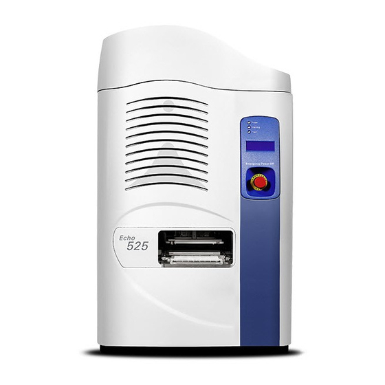
Page 27: System Overview
Back Panel Front Panel This topic provides a brief description of the components located on the front panel of the Echo 525 Liquid Handler. Figure 10: Echo 525 Liquid Handler front panel Door: The door protects the operator from the moving mechanisms blocks stray light emitted by the barcode scanner lasers. -
Page 28: Back Panel
CHAPTER 3 | General Description Back Panel This topic provides a brief description of the components located on the back panel of the Echo 525 Liquid Handler. Figure 11: Echo 525 Liquid Handler back panel AC power and fuse compartment: The AC power and fuse compartment (also called the power input module) contains the main Echo Liquid Handler power on/ off switch, AC power outlet, and fuse compartment. -
Page 29: Component Description
USER GUIDE | Echo® 525 Liquid Handler User Guide Component Description Ethernet connection: RJ-45 Ethernet network port connects the Echo Liquid Handler to a PC or to a network. For more information, see Data Connection. Tubing and hose connections: The Echo Liquid Handler has connections for two chiller lines (supply and return), pressurized clean dry air (CDA) and a vacuum. -
Page 30: Source Plate Gripper Stage
To keep the source plate secure, the plate gripper includes a plate insert designed for specific plate types. See the following table of plate inserts. Table 1: Plate Inserts for Echo 525 Liquid Handler Labcyte Plate Insert Part# Insert Size... - Page 31 USER GUIDE | Echo® 525 Liquid Handler User Guide Component Description Figure 15: Source plate gripper stage (entire assembly) The plate insert will be moved into the correct position by the gripper arm when the source plate gripper stage moves through the door.
-
Page 32: Destination Plate Gripper Stage
Component Description CHAPTER 3 | General Description Destination Plate Gripper Stage The destination plate gripper stage is the upper plate stage that extends from the Echo Liquid Handler. The plate gripper holds the microplate that will receive the liquid being transferred. When you load the plate onto the plate gripper, well A1 goes into the upper left corner (nearest the Echo model number). -
Page 33: Status Indicator Lights
Labcyte recommends that you refill the coupling fluid bottle as soon as possible after the Warning light has been turned on. For more information, see Echo Coupling Fluid Maintenance. -
Page 34: Lcd Screen
Component Description CHAPTER 3 | General Description Fault Light The states for the fault light are listed below: Off: Normally the Fault light is turned off, indicating that the Echo Liquid Handler is functioning correctly. Red: The Fault light is turned on when any of the following conditions are true: The user-supplied compressed air supply is low ( <... - Page 35 For more information , see Motion Calibration. Note: If you cannot determine the original problem, or you cannot correct the problem, you must arrange for a Labcyte field engineer to restore your Echo Liquid Handler to normal use. PN | 001-11665...
-
Page 36: Anti-Static Bars
Figure 21: Anti-static bars Barcode Scanner The Labcyte Echo Liquid Handler optionally includes one or more barcode scanners. The location of each scanner depends on the location of your barcode labels on the microplates. You can purchase one or more barcode scanners to add to your Echo Liquid Handler that will read and report barcoded microplates. - Page 37 Note: The readable bar width expresses the range in which the width of thin barcode bars (narrow bar width) is readable. The Echo Liquid Handler can be configured to read four different barcode formats. By default, Labcyte installs the barcode formats in bold listed above.
-
Page 38: Ac Power And Fuse Compartment
115 VAC, 10 A, FAST (P/N 001-3966) 200–240 V 50/60 Hz 250 VAC, 5 A, FAST (P/N 001-3967) The fuse compartment for the Echo Liquid Handler contains two AC power fuses. If a fuse requires replacement, contact Labcyte Service and Support (see Contact Information). -
Page 39: Coupling Fluid Bottle
USER GUIDE | Echo® 525 Liquid Handler User Guide Component Description Coupling Fluid Bottle The Echo system comes with a 1000 mL coupling fluid bottle. Figure 26: Coupling fluid bottle The Echo Liquid Handler detects if the coupling fluid bottle falls below a specific level. If the sensor indicates that the fluid has fallen below the minimum level, a low fluid volume alert warning is sent to the Echo server. -
Page 40: Air Compressor
Note: The Junair OF302-4B compressor is only 115 VAC/60Hz and is only suitable for North America. The user must also provide a fitting between the compressed air supply and the Echo Liquid Handler. Labcyte provides the compressed air line and fitting with the Echo Liquid Handler, but the customer must provide a source compatible with 170 in ID/.250 in OD tubing. - Page 41 USER GUIDE | Echo® 525 Liquid Handler User Guide Component Description Figure 28: Junair OF302-4B oil-less compressor Note: Maximum consumption by Echo Liquid Handler does not exceed 1 cfm at 150 PSI. PN | 001-11665...
-
Page 42: Vacuum Pump
Echo Liquid Handler vacuum line. The supplied vacuum line is HercoBraid, 9.5 mm (3/8 in) ID, 9.5 mm (5/8 in) OD (RyanHerco P/N 0512-072). A standalone Vacuubrand MZ 2S-NT vacuum system can be purchased from Labcyte (Part #001-8104). This vacuum is a dual voltage/cycle compatible system. - Page 43 USER GUIDE | Echo® 525 Liquid Handler User Guide Component Description Figure 29: Vacuubrand MZ 2S-NT vacuum system When vacuum demand is at its highest, a 10 L surge tank (provided with the Echo Liquid Handler) ensures a continuous source of vacuum.
-
Page 44: Fluid Chiller
Component Description CHAPTER 3 | General Description Fluid Chiller The Echo's Liquid Handler's peristaltic pump pushes the coupling fluid through the chiller to maintain the coupling fluid temperature. Coupling fluid temperature control The recommended Echo Liquid Handler coupling fluid temperature operating window is 22.1°C ± 0.9°C. This temperature can be viewed on the Diagnostics tab of the Echo Liquid Handler software. -
Page 45: Fluidics Panel
USER GUIDE | Echo® 525 Liquid Handler User Guide Component Description Fluidics Panel The fluidics panel contains tubing and hose connections to the following components: Figure 31: Fluidics panel Note: Labcyte provides the 001-12466 accessory kit with all the necessary connectors and tubing. PN | 001-11665... - Page 46 Component Description CHAPTER 3 | General Description Chiller tubing: The chiller tubing provides the coupling fluid circulation path between the Echo Liquid Handler and the chiller. The chiller maintains the fluid temperature at 22°C. The tubing is sufficiently long to allow the chiller to be placed on the floor below the Echo Liquid Handler (for reduced vibration and good ventilation).
-
Page 47: Barcodes
Barcodes The Labcyte Echo Liquid Handler optionally includes one or more barcode scanners. The location of each scanner depends on the location of your barcode labels on the microplates. You can only specify one location at-a-time for a plate. That is, you can specify that a barcode is on the West, South, or East side. If the Echo has been configured for West-side reads, then both source and destination plates must have West-side barcodes. -
Page 48: Chiller
001-11168 SMC Chiller Upgrade Kit (Must be purchased separately) A Labcyte service representative will set up the chiller with the Echo system. Refer to the following sections for safety information, equipment setup (if the Echo system is relocated), operation, and troubleshooting. - Page 49 Chiller Setup A Labcyte service representative will set up the chiller during Echo Liquid Handler installation. If you need to set up the chiller again (for example, after relocation of the Echo Liquid Handler), use the procedure below. The references in parenthesis throughout the steps refer to the callouts in the chiller image below.
- Page 50 Component Description CHAPTER 3 | General Description Note: It is assumed that the chiller is being set up in a typical laboratory environment. Avoid direct exposure to water/steam, oil, chemicals, or prolonged sunlight. 2. Ensure the chiller is setup so that there is free airflow around the air inlets at the front of the chiller and at the air outlet and cooling fins at the back of the chiller.
- Page 51 USER GUIDE | Echo® 525 Liquid Handler User Guide Component Description Toggle the power switch to the | or on position. The chiller control panel lights up and displays the firmware version for about a second. It displays the normal operation screen. The chiller starts controlling temperature immediately.
- Page 52 Toggle the chiller power using the switch on the front panel. If the unit ERR01 System Error does not recover, contact Labcyte service personnel. Toggle the chiller power using the switch on the front panel. If the unit ERR02 System Error does not recover, contact Labcyte service personnel.
-
Page 53: Consumables
USER GUIDE | Echo® 525 Liquid Handler User Guide Component Description Consumables The consumables and corresponding specifications recommended to be used with the Echo Liquid Handler are listed below: Table 5: Compatible Source Plates for Echo 525 Liquid Handler 384PP Plus Plate and Echo Qualified 384PP Plate 384LDV Plus Plate 384PP TC Plate... - Page 54 Recommended to remove bubbles caused by the filling process or reagent outgassing. Note: The 384PP Plus plate is the optimal source plate for the Echo 525 Liquid Handler. The 384PP plate may be used, but accuracy and precision may be compromised for certain fluid types and destination plates. The 384PP Plus plate and the Echo Qualified Reservoir are only designed for use with the Echo 525 Liquid Handler and are not compatible with any other models of Echo Liquid Handlers.
- Page 55 USER GUIDE | Echo® 525 Liquid Handler User Guide Component Description Note: By design, the 384PP Plus plate has improved drop placement. Therefore, Labcyte recommends using 384PP Plus plates rather than 384PP plates when transferring to 1536 targets. Use of 1536 well plates as destination plates is application dependent.
- Page 56 Component Description CHAPTER 3 | General Description Table 7: System Throughput (continued) Dispense Volume Per Destination Plate Fill Source Plate Type Destination Plate Type Dispense Type Destination Well Cycle Time (min) 384PP Plus 1536 4x384:1536 1 µL 12.4 Note: 384PP Plus plates and 384PP TC plates have the same system throughput values.
-
Page 57: Critical Micelle Concentrations
Membrane Protein Solubilization: Recent Advances and Challenges in Solubilization of Serotonin Receptors. 2005. (Lower bound) http://onlinelibrary.wiley.com/doi/10.1080/15216540500167237/pdf Colloids and Surfaces A: Physicochem. Eng. Aspects 290 (2006) 206–212. Client PC (sold by Labcyte) Client PC specifications (Dell OptiPlex XE2): PN | 001-11665... - Page 58 Accessories: Microsoft® Office 2016 Monitor, 22 in, DVI-D/DP/VGA Dell USB Keyboard, Black Dell MS111 USB Optical Mouse, OptiPlex and Fixed Precision Labcyte Mousepad Software specifications: Optionally, the following Echo software applications are available for purchase: Echo Plate Reformat Echo Dose-Response...
- Page 59 USER GUIDE | Echo® 525 Liquid Handler User Guide Component Description This page was intentionally left blank PN | 001-11665...
-
Page 60: Installation And Relocation
Maximum consumption by Echo Liquid Handler does not exceed 1 cfm at 150 PSI The user must also provide a fitting between the compressed air supply and the Echo Liquid Handler. Labcyte provides the compressed air line and fitting with the Echo Liquid Handler, but the customer must provide a source compatible with 170 in ID/.250 in OD tubing. - Page 61 Standalone vacuum with surge tank (10 L): 100 Torr (133 mbar, 26 in Hg Vac), minimum pumping speed 2.0 m Note: A standalone Vacuubrand MZ 2S-NT vacuum system can be purchased from Labcyte (Part #001- 8104). For more information, see the Vacuum Pump topic.
- Page 62 Note: The instrument can be installed with a minimum of 2.5 cm (1 in) if there is sufficient space to lift the top and slide it all the way forward. Talk to your Labcyte service representative for additional details. Front: It is recommended to have 40.6 cm (16 in) to allow sufficient clearance to load and unload microplates by hand or by robot.
-
Page 63: Additional Components
Client + Server software onto a workstation, it must contain an Intel Core™ 2 Duo processor or better. Note: A Client PC can be purchased directly from Labcyte (Part #ECHO-Client Computer). For information on the Client PC available from Labcyte, see the Client PC (sold by Labcyte) topic. - Page 64 Pre-Installation Requirements CHAPTER 4 | Installation and Relocation AC power and configuration and fuses: Table 8: Electrical Configurations for the Echo Liquid Handler Voltage Frequency Power Fuse 100-120 V 50 Hz 10 A 115 VAC, 10 A, FAST (P/N 001-3966) 100-120 V 60 Hz 10 A...
-
Page 65: Installation Overview
Installation Overview Installation Overview The Labcyte Echo Liquid Handler is installed by Labcyte field engineers. The following is a brief overview of the hardware and software installation steps they perform: 1. Unpack the Echo Liquid Handler and place it in the area that meets the minimum operating space requirement. -
Page 66: Echo Liquid Handler Software Installation
Echo Liquid Handler Software Installation Labcyte installs the Echo Liquid Handler software onto the client PC that is connected to the Echo Liquid Handler. If you need to install the software onto additional computers, such as network PCs, use the instructions provided in this section. See... - Page 67 USER GUIDE | Echo® 525 Liquid Handler User Guide Echo Liquid Handler Software Installation Figure 36: Entering host name 3. Click Next and then Install to start the installation. Edit or verify the previously entered information or selections by clicking the Back button.
- Page 68 4. Click the Finish button when the installation is done. Note: Read the release notes for information about the version of software being installed. The release notes are stored in the Labcyte Echo Liquid Handler folder on your Windows Desktop for later viewing.
-
Page 69: Echo Liquid Handler Software Installation Procedure For Microsoft® Windows 10 64-Bit Os
USER GUIDE | Echo® 525 Liquid Handler User Guide Echo Liquid Handler Software Installation Echo Liquid Handler Software Installation Procedure for Microsoft® Windows 10 64-bit OS The minimum Client PC specifications for the Echo Liquid Handler software must be configured before installing Windows 10. For more information, see Client PC (minimum requirements). - Page 70 Echo Liquid Handler Software Installation CHAPTER 4 | Installation and Relocation 4. If a window appears with a request for the additional files, click Download files from Windows Update. 5. Wait for the installation to finish before moving on to the next steps.
- Page 71 9. Restart the PC to complete the installation. Change the following properties for Echo Liquid Handler Software compatibility: 1. Navigate to the Echo Liquid Handler software installation folder, C:\Program Files (x86)\Labcyte\Bin\Release folder. 2. Right-click on the MedmanGUI.exe and select Properties.
- Page 72 Echo Liquid Handler Software Installation CHAPTER 4 | Installation and Relocation 4. Click Change settings for all users.
- Page 73 8. Execute setup.exe to complete the installation of the Echo Software Application in Windows 7 Compatibility mode. Echo Software Application Compatibility Preparation 1. For each Echo Software Application, navigate to C:\Program Files (x86)\Labcyte\ApplicationName folder. 2. Right-click on ApplicationName.exe and select Properties.
-
Page 74: Uninstall The Echo Liquid Handler Software
4. Select Echo Liquid Handler and click Remove. Upgrade the Echo Liquid Handler Software Upgrading the software requires a new Echo Liquid Handler software CD. Contact Labcyte Service and Support for the most current version. For more information, see Contact Information. -
Page 75: Reinstall The Echo Liquid Handler After A Move
After the move, use the following procedure to restore an Echo Liquid Handler to normal operation. Note: The steps below apply to a standalone configuration of the Echo Liquid Handler. If the Echo Liquid Handler is integrated into an Access system, please contact Labcyte Service and Support. For more information, see Contact Information. - Page 76 Instrument Relocation CHAPTER 4 | Installation and Relocation 6. Connect the chiller. Attach the plastic tubing between the chiller and the Echo Liquid Handler. Figure 40: Tubing connections on the chiller Caution: Do not run the pump until the chiller tubing is connected. Running the pump without the chiller tubing may damage other system components.
- Page 77 USER GUIDE | Echo® 525 Liquid Handler User Guide Instrument Relocation Figure 41: Tubing connections on the Echo system 7. Use the “cross-over” Ethernet cable to connect the Echo Liquid Handler to the client PC. The client PC should have the Echo Liquid Handler software already installed.
-
Page 78: Software
Stacking: transferring liquid from several source plates to a single destination plate Note: The Echo 525 Liquid Handler client software that comes standard with the Echo instrument is designed for 384- well and 1536-well plate replication protocols. However, the Echo 525 Liquid Handler software does not currently support the 6-well Echo Qualified Reservoir plate. -
Page 79: Supported Labware
USER GUIDE | Echo® 525 Liquid Handler User Guide Supported Labware Supported Labware The table below lists the Echo qualified source microplates that are available. Table 10: Compatible Source Plates for Echo 525 Liquid Handler 384PP Plus Plate and Echo Qualified 384PP Plate 384LDV Plus Plate 384PP TC Plate... -
Page 80: Startup/Shutdown
Before preceding, ensure the hardware and client PC software installations are complete. All fluid, air, and electrical connections should be complete and functioning. Your Labcyte field engineer performs a set of function tests to ensure that the system is operating correctly. - Page 81 The Echo Liquid Handler software is not configured to connect to the instrument (IP address or hostname is missing or incorrect). Check for the cause, attempt to resolve the problem, and try to launch the software again. If the message persists, call Labcyte Service and Support.
- Page 82 Startup/Shutdown CHAPTER 5 | Software Echo Initialization The Echo Liquid Handler performs a system initialization that includes the following actions: All three stages move to their home position: Source stage moves front to rear on its Y axis. Destination stage moves left to right on its X axis, front to rear on its Y axis, up and down on its Z axis, and partially rotates on its theta axis.
-
Page 83: Launch Echo Liquid Handler Software
The Echo Liquid Handler software can be launched by either of the following methods: Open the Labcyte Echo folder on the desktop and double-click the icon for your Echo Liquid Handler. Figure 43: Starting the Echo Liquid Handler from the Windows Desktop Go to Start >... - Page 84 Startup/Shutdown CHAPTER 5 | Software Figure 45: Echo Liquid Handler welcome screen...
-
Page 85: Turn Off Echo Power
USER GUIDE | Echo® 525 Liquid Handler User Guide Startup/Shutdown Turn Off Echo Power You may need to power off the Echo Liquid Handler for any of the following reasons: Extended periods of non-use Preventive maintenance Service or repair Power interruptions, such as scheduled facility power interruptions Moving it to a new location When you need to turn the power off, use the following procedure: 1. - Page 86 Startup/Shutdown CHAPTER 5 | Software Figure 47: Location of Emergency Motion Off switches To use the Emergency Motion Off switch in an emergency, push it in. To reset the Emergency Motion Off switch, turn the knob clockwise until it pops out (see arrows etched in the knob). Note: If the Emergency Motion Off switch is used, if you have a protocol running, it may be interrupted and may need to be restarted.
- Page 87 For more information , see Motion Calibration. Note: If you cannot determine the original problem, or you cannot correct the problem, you must arrange for a Labcyte field engineer to restore your Echo Liquid Handler to normal use. PN | 001-11665...
-
Page 88: Echo Liquid Handler Software
Echo Liquid Handler Software The Labcyte Echo Liquid Handler comes with user software. The Echo Liquid Handler software provides a Windows-based graphical user interface (GUI). The user can control the Echo Liquid Handler and execute most of its functions which are listed... -
Page 89: Main Screen
USER GUIDE | Echo® 525 Liquid Handler User Guide Echo Liquid Handler Software Main Screen The Echo Liquid Handler software opens in the Main screen. The Main screen shows tabs for each major function and user interactive area for selecting from a list of protocols or clicking options or function keys. The first tab shows the Protocols window. Below the user interactive area is the status window. -
Page 90: Protocols Window
Echo Liquid Handler Software CHAPTER 5 | Software The status windows also display specific types of errors that the system encounters during a protocol run. About and Help menu (not shown): Right-clicking on a tab window background, will display a menu that provides two choices: About and Help. - Page 91 USER GUIDE | Echo® 525 Liquid Handler User Guide Echo Liquid Handler Software Table 12: Example Protocols Source Destination Transfer map type (full) Transfer map type (partial) plate plate down-stacking quadrant: 4 regions from 1 source plate down-stacking interleaved: 2x2, or every 384-well 96-well to 4 destination plates...
- Page 92 Echo Liquid Handler Software CHAPTER 5 | Software Create a Liquid Transfer Protocol The liquid transfer protocol specifies how much fluid will be transferred from the source microplate to the destination microplate, and in what well order—a plate map that the Echo instrument uses to perform the transfer. For example, a simple transfer protocol would transfer reagent from all source wells to the matching destination wells, replicating the contents of the source plate.
- Page 93 Source Plate Type: Select a source plate type from the first drop-down list. Note: Only Echo qualified source microplates are listed in the Source Plate drop-down list. Contact Labcyte to add more source plates. For more information, see Contact Information.
- Page 94 Echo Liquid Handler Software CHAPTER 5 | Software 2. Click the Next button. The second Add New Protocol wizard dialog box opens. Figure 52: Add new protocol wizard, page 2 of 2 3. Transfer Wells: Click the View/Define button to select the wells to be transferred from the source plate. Select the source plate wells that contain the reagent to be transferred.
- Page 95 USER GUIDE | Echo® 525 Liquid Handler User Guide Echo Liquid Handler Software Click the OK button to return to the previous screen. Figure 53: Define wells dialog box 4. Number of Copies: Enter the number of times the protocol will be executed. The valid range is 1 to 10,000 copies. The operator is prompted to load and unload the source microplate and the specified number of destination microplates.
- Page 96 Echo Liquid Handler Software CHAPTER 5 | Software...
- Page 97 USER GUIDE | Echo® 525 Liquid Handler User Guide Echo Liquid Handler Software Create a New 384:1536 Protocol Definition Create a new 384:1536 protocol definition using the stacking features of the Add New Protocol wizard. Reagent from four 384-well source plates can be transferred to a single 1536-well destination plate. Note: If the new liquid transfer protocol requires a new destination microplate definition, create it before running the Add New Protocol wizard.
- Page 98 Echo Liquid Handler Software CHAPTER 5 | Software 2. Click the Next button to open the second page of the Add New Protocol wizard dialog box. Figure 57: Add new protocol wizard, page 2 of 3 Enter the following information: Transfer Map Type: Select an interleaved or a quadrant liquid transfer protocol type.
- Page 99 USER GUIDE | Echo® 525 Liquid Handler User Guide Echo Liquid Handler Software 3. Click the Next button to open the third Add New Protocol wizard dialog box. Figure 58: Add new protocol wizard, page 3 of 3 You must define a fluid transfer map for each of the source microplates used. PN | 001-11665...
- Page 100 Echo Liquid Handler Software CHAPTER 5 | Software 4. Click the View/Define button to create a transfer map for the first source plate. The Define Wells dialog box shows the wells that are available for transfer. Select the wells you want to include in the transfer. Repeat this step for the other source plates and click the OK button.
- Page 101 USER GUIDE | Echo® 525 Liquid Handler User Guide Echo Liquid Handler Software 5. Click the Finish button after all four transfer maps have been created. Figure 60: 384:1536 protocol finished PN | 001-11665...
- Page 102 Echo Liquid Handler Software CHAPTER 5 | Software Create a Transfer Map A transfer map must be created for each source microplate. The transfer map defines which source microplate wells contain reagent that will be transferred to the destination plate. When you click the View/Define button, the Define Wells dialog box opens.
- Page 103 USER GUIDE | Echo® 525 Liquid Handler User Guide Echo Liquid Handler Software Figure 62: Multiple regions defined in a transfer map Click the OK button to save the transfer map definition with this protocol. Edit an Existing Protocol Definition To edit an existing protocol definition, click the Edit button or double-click the protocol name in the protocol list.
- Page 104 Echo Liquid Handler Software CHAPTER 5 | Software Figure 64: Edit 384:1536 protocol dialog box Any parameter of a user-defined protocol can be edited; however, the destination plate type cannot be changed from 384-well to 1536-well or vice versa. Remove an Existing Protocol Definition If a protocol must be deleted, select the protocol name and click the Remove button.
- Page 105 USER GUIDE | Echo® 525 Liquid Handler User Guide Echo Liquid Handler Software 3. Collect the microplates that will serve as destination plates to receive the reagent. A destination microplate definition must exist or be created. For example, knowing the plate height of the destination microplate allows the Echo Liquid Handler to lower the destination microplate into very close proximity to the source microplate, improving droplet ejection accuracy and reliability.
- Page 106 Echo Liquid Handler Software CHAPTER 5 | Software Figure 65: Protocol selected to be run...
- Page 107 USER GUIDE | Echo® 525 Liquid Handler User Guide Echo Liquid Handler Software 2. Click the Next button. The door will open and the source plate gripper stage will extend outside of the Echo Liquid Handler. 3. Load your source microplate with well A1 closer to the instrument’s inner-left corner. Click the Next button. The source plate gripper stage retracts into the Echo Liquid Handler and the destination plate gripper stage is extended outside of the Echo Liquid Handler.
- Page 108 Echo Liquid Handler Software CHAPTER 5 | Software Using the data contained in your destination microplate definition, the protocol definition, and the source microplate survey just performed, droplets are ejected from each specified source microplate well into the corresponding destination microplate well.
-
Page 109: Labware Window
USER GUIDE | Echo® 525 Liquid Handler User Guide Echo Liquid Handler Software The liquid transfer protocol is finished. Labware Window The Labware window is used to manage source and destination microplate definitions. Figure 66: Labware window Plate Name List: The Plate Name List contains all of the source and destination plates that have been defined for your system (may vary from the list in the previous figure). - Page 110 Source Plates Labcyte names every source plate with familiar plate naming convention, such as 384PP and abbreviated liquid types, such as AQ, to help operators identify the plate names. This section describes the convention we use. Structure of the source plate name: No.
- Page 111 Echo instruments and tested as Labcyte Echo® qualified microplates. For this reason, new source plates cannot be defined by the user. For existing source plates, only the barcode location can be edited (see figure below). Contact Labcyte to add more source plates.
- Page 112 Echo Liquid Handler Software CHAPTER 5 | Software Manage Labware Specifications Adding a new destination plate, or editing an existing destination plate, are virtually the same process. On the Labware tab click either Add or Edit. The Destination Plate Specification dialog box will open. Note: The edit window for the source plate specification looks the same, but only the barcode location can be edited.
- Page 113 USER GUIDE | Echo® 525 Liquid Handler User Guide Echo Liquid Handler Software Figure 69: Selecting barcode locations Plate Dimensions Two illustrations identify the destination plate dimensions that must be entered. These dimensions may already be specified in the SBS standards. Figure 70: Plate dimensions A, B, C, and D A and B:Well A1 X/Y offsets.
- Page 114 Echo Liquid Handler Software CHAPTER 5 | Software C: X center spacing: Dimension C specifies the horizontal distance between well centers in millimeters. That is, the distance between wells A1, A2, A3, and so on. Example: For a 384PP plate type, C is 4.5 mm. The valid range for C is 0.05 mm to 9.00 mm.
- Page 115 USER GUIDE | Echo® 525 Liquid Handler User Guide Echo Liquid Handler Software Example: For a 384PP_AQ_BP, 65.0 μL. The valid range for H is greater than 0.0 μL. Note: The destination well volume property is currently used for customer plate dimension management. The OK button saves the new or edited specification.
-
Page 116: Diagnostics Window
Echo Liquid Handler Software CHAPTER 5 | Software Diagnostics Window The Diagnostics window provides the following control and monitoring options: In the Device control and status section, the user can control many of the Echo internal devices and mechanisms. The current position of those devices and mechanisms is reported by green lamp indicators. - Page 117 USER GUIDE | Echo® 525 Liquid Handler User Guide Echo Liquid Handler Software Figure 73: Diagnostics tab PN | 001-11665...
- Page 118 Echo Liquid Handler Software CHAPTER 5 | Software Device Control You have access to precise Echo device control. The ability to command internal mechanism movement is useful during maintenance, troubleshooting, and diagnostic procedures. Access to device control is found in several areas of the Echo Liquid Handler software: The Device Control and Status section of the Diagnostics window uses eleven sets of checkboxes and status indicators that allow you to control the Echo Liquid Handler.
- Page 119 USER GUIDE | Echo® 525 Liquid Handler User Guide Echo Liquid Handler Software Source Plate In/Out and Presence The source plate gripper stage can be commanded to extend outside or to retract back inside the Echo Liquid Handler. Select the appropriate checkbox.
- Page 120 Echo Liquid Handler Software CHAPTER 5 | Software Green = Plate present Flip Destination Plate The Echo Liquid Handler can be commanded to flip its destination plate gripper stage into the inverted or upright positions. Select the appropriate checkbox. If the destination plate gripper stage is still inside the Echo Liquid Handler when commanded to flip upright, a Flip Dest Plate Up Error will appear.
- Page 121 USER GUIDE | Echo® 525 Liquid Handler User Guide Echo Liquid Handler Software Coupling Pump Direction Normal/Reverse The Echo Liquid Handler can be commanded to run its coupling fluid pump in the normal or reverse direction. The associated indicator lights report the direction of coupling fluid pump flow. Note: Do not run the pump in reverse for an extended period.
- Page 122 Echo Liquid Handler Software CHAPTER 5 | Software The user-supplied compressed air supply is <552 kPa (<80 psi). For more information, see Compressed Air Pressure Indicator. The user-supplied vacuum pressure is <78 kPa (<15 in Hg Vac). For more information, see Vacuum Supply Pressure Indicator.
- Page 123 Maintenance. Waste Bottle Indicator The waste bottle is not necessary for the Echo 525 Liquid Handler. The indicator will always be Green. Focus Calibration Indicator Periodically, the focal length of the acoustic transducer should be checked. When this period of time has expired, the Focus Calibration indicator turns yellow.
- Page 124 Echo Liquid Handler Software CHAPTER 5 | Software Coupling Fluid Temperature and Indicator The coupling fluid temperature inside the Echo Liquid Handler is reported in degrees Celsius. The operating range for the coupling fluid temperature is 22.1°C ± 0.9°C. The coupling fluid controls the temperature of the acoustic transducer. A correct and stable acoustic transducer temperature is required to maintain accurate and precise liquid transfers.
- Page 125 USER GUIDE | Echo® 525 Liquid Handler User Guide Echo Liquid Handler Software Diagnostic Procedures In the Miscellaneous section, there is a drop-down list of diagnostic procedures and a Launch button. The following diagnostic procedures are available: Dry Plate Move to Well Diagnostic Survey Dry Plate The Dry Plate procedure vacuums the water film off the bottom of a source plate.
- Page 126 Echo Liquid Handler Software CHAPTER 5 | Software 1. Select Move to Well and click the Launch button. The Move to Well dialog box is displayed. 2. Enter the row and column address of the well. Example: C15. Figure 81: Move to well function 3.
- Page 127 USER GUIDE | Echo® 525 Liquid Handler User Guide Echo Liquid Handler Software 3. Click the Launch button. The Survey window will open. Figure 83: Survey Procedure 4. From the Name drop-down list, select the correct source plate type. PN | 001-11665...
- Page 128 Save Results to Disk. Select this checkbox to automatically store the results of the acoustic survey in the client PC data directory (C:\Program Files\Labcyte\Medman\Data). Ignore Source Plate Sensor. Select this checkbox to resolve problems with fitting a source plate onto the source plate gripper stage.
- Page 129 USER GUIDE | Echo® 525 Liquid Handler User Guide Echo Liquid Handler Software Figure 85: Diagnostic survey plate parameters PN | 001-11665...
- Page 130 (homogeneous), or processed (inhomogeneous) survey data depending on which Post Processing radio button is selected. In the Results section, raw data collected during the survey is displayed. This information is used only by Labcyte personnel during troubleshooting or system analysis.
- Page 131 USER GUIDE | Echo® 525 Liquid Handler User Guide Echo Liquid Handler Software Figure 87: Diagnostic survey file saved PN | 001-11665...
-
Page 132: Calibration Window
Echo Liquid Handler Software CHAPTER 5 | Software Calibration Window Several Echo mechanisms can be user-calibrated. The following motion, power, and acoustic transducer related calibration procedures are found in the Calibration window. Figure 88: Calibration window... - Page 133 Note: Normally the register calibration will not need to be performed by a user. However, it can be useful during certain repair, diagnostic, or recovery procedures. Perform the register calibration only as directed by Labcyte personnel. If register calibration is required, use the following procedure:...
- Page 134 Echo Liquid Handler Software CHAPTER 5 | Software 1. Click Register in the Calibration window. The Plate Registration window opens. Figure 90: Plate registration window 2. Select the source plate type from the drop-down menu. 3. Click the Present button to extend the source plate gripper stage. 4.
- Page 135 USER GUIDE | Echo® 525 Liquid Handler User Guide Echo Liquid Handler Software Figure 91: Plate registration confirmed PN | 001-11665...
- Page 136 Note: Normally a manual power calibration will not need to be performed by a user. However, it can be useful during certain repair, diagnostic, or recovery procedures. Perform power calibration only as directed by Labcyte personnel. If manual power calibration is required, use the following procedure: 1.
- Page 137 USER GUIDE | Echo® 525 Liquid Handler User Guide Echo Liquid Handler Software The most recent power calibration record stored in the Echo database is read. This data will be used in the next step. An RF pulse is generated. Several RF measurements are taken.
- Page 138 If the difference is larger than a preset threshold, users should call Labcyte support to ensure the system is running properly before accepting the focal length new value.
- Page 139 USER GUIDE | Echo® 525 Liquid Handler User Guide Echo Liquid Handler Software Figure 94: Focus Calibration Focus Calibration Check A focus calibration check should be performed periodically. The Echo Liquid Handler keeps track of how long it has been since the last focus calibration check was performed.
- Page 140 CHAPTER 5 | Software Figure 95: System Status section Caution: When the Focus Calibration indicator is yellow, Labcyte strongly recommends that the user execute the Focus calibration wizard as soon as possible. 1. In the Transducer Focus Calibration window, click the Focus button.
- Page 141 USER GUIDE | Echo® 525 Liquid Handler User Guide Echo Liquid Handler Software 4. Click the Finish button to complete the focus calibration procedure. Figure 97: Focus calibration step 2 (new focal length calibration not required) PN | 001-11665...
-
Page 142: Advanced Window
Echo Liquid Handler Software CHAPTER 5 | Software Advanced Window The Advanced window provides additional controls that may be useful to the experienced Echo user. Figure 98: Advanced Window... - Page 143 Setting the survey interval to 0 turns off plate surveying which is not recommended. Assume Homogeneous Plate: When a source plate is surveyed, the Echo 525 Liquid Handler creates a map of the entire plate. This map is post-processed using a moving average filter if the Assume Homogeneous Plate checkbox is selected.
- Page 144 Echo Liquid Handler Software CHAPTER 5 | Software Advanced Solvent Concentration Note: The Solvent Concentration function in the Advanced tab of the Echo Liquid Handler software uses units of acoustic impedance (MRayl). In cases where there are two simple solvent fluids, Water and Glycerol,fluid concentration can be correlated to acoustic impedance.
- Page 145 USER GUIDE | Echo® 525 Liquid Handler User Guide Echo Liquid Handler Software To predefine a solvent concentration: 1. Select the Use predefined: checkbox to allow the Echo Liquid Handler to use the predefined concentration map. 2. Click the Define: button to open the Solvent Platemap dialog box. Figure 99: Solvent Platemap Dialog Box Note: Use this function carefully and only when you need to specify a fixed measurement and override the Echo measurement.
-
Page 146: Status Window
Client log messages: Messages in the client log window originate in the client PC. In addition to being displayed, the client messages are stored on the client PC. The exact location depends on the Echo Liquid Handler software installation. The default location for the client log files is: C:\Program Files\Labcyte\Medman\Data The most recent client log file is named: client_localhost_MedmanGUI.txt and older client log files are named: client_localhost_MedmanGUI.old.0.txt, client…1.txt,client…2.txt, and so on. - Page 147 Echo Liquid Handler software window. All: All message types (debug, warning, info, and error) are displayed in the client and server log windows. Debug: Debug messages are generally not of use to Echo users. They provide detailed information to Labcyte representatives.
-
Page 148: Maintenance And Service
If the coupling fluid level is at 350 mL or less, clean and refill the coupling fluid bottle. For more information, see Echo Coupling Fluid Maintenance. If the coupling fluid is cloudy, purge and replace the coupling fluid. Notify Labcyte Service and Support for further instructions. For more information, see Clean and Refill the Coupling Fluid Bottle Contact Information. -
Page 149: Echo Maintenance Alerts
USER GUIDE | Echo® 525 Liquid Handler User Guide Maintenance Schedule Echo Maintenance Alerts The Echo Liquid Handler contains internal checks to ensure that it performs liquid fills under optimal conditions. If, for example, the coupling fluid temperature is outside the normal range (21.2°C – 23.0°C), a yellow warning light appears on the Echo front and back panels. -
Page 150: Scheduled Maintenance
Emergency Motion Off Switch The EMO (Emergency Motion Off) switch has been activated. Scheduled Maintenance Labcyte recommends that the following maintenance procedures be performed on a regular basis. Maintenance promotes accurate, precise, and reliable fluid transfers. Every Two Weeks Once Per Month... -
Page 151: Maintenance Procedures
Other than the user-level maintenance procedures described, all service and repair must be performed by Labcyte field engineers. If you have questions regarding what may be serviced by an Echo user, please call Labcyte Service and Support. For more information, see Contact Information. - Page 152 Maintenance Procedures CHAPTER 6 | Maintenance and Service Clean and Refill Materials Required The following materials are required to refill the coupling fluid bottle: Type 1 Ultrapure Water, sufficient to fill the 1 L bottle to ~900mL. Gloves for protection when handling the fluids Paper towels or shop cloths to deal with any unexpected fluid leaks An empty, clean 1000 mL coupling fluid bottle (square bottle catalog number ECHO-AL15-S) The fluidic system will be emptied, purged, and refilled several times, therefore take note of the following caution:...
- Page 153 USER GUIDE | Echo® 525 Liquid Handler User Guide Maintenance Procedures Figure 105: Diagnostic tab highlighting coupler pump 3. Select the checkbox for Coupler Pump Direction Reverse. 4. Select the checkbox for Coupler Pump On. The coupling fluid inside the Echo fluidic circuit will be pumped back into the coupling fluid bottle.
- Page 154 8. Visually inspect the used coupling fluid. It should not be cloudy or visually contaminated with algae or other substances. Warning: If there is significant contamination, and/or signs of corrosion in the coupling fluid tubing, in the debubbler, at the nosecone, or anywhere else, please call Labcyte Service and Support. For more information, see Contact Information.
- Page 155 USER GUIDE | Echo® 525 Liquid Handler User Guide Maintenance Procedures 1. Turn off the coupling fluid pump. 2. In the Diagnostic window of the Echo Liquid Handler software, select the reverse coupling fluid pump direction (Coupling Pump Direction Reverse). For more information, see Coupling Pump Direction Normal/Reverse.
-
Page 156: Water Filter Maintenance
To ensure that the coupling fluid is filtered effectively, Labcyte will replace the water filter at the annual Preventative Maintenance. If the water filter traps excessive material, it may become clogged or shed trapped particles before the annual Preventative Maintenance is due. - Page 157 USER GUIDE | Echo® 525 Liquid Handler User Guide Maintenance Procedures 3. Disassemble the water filter. 1. Unscrew and remove the clear water filter bowl (do not remove the housing from the tubing). 2. Take note of the installed position and remove the stainless steel mesh water filter element. Note: Handle the water filter element by the black plastic cage only and do not touch the steel mesh.
-
Page 158: Clean The Anti-Static Bars
Maintenance Procedures CHAPTER 6 | Maintenance and Service Abrasives or sharp-edged tools Heat as the water filter is not rated to be autoclavable Clean the Anti-Static Bars The Echo Liquid Handler uses two anti-static bars to neutralize any static charge on the source and destination plates. The anti- static bars are just inside the door, one right below and the other right above the door opening. -
Page 159: Cycle Fluid Through Echo System
USER GUIDE | Echo® 525 Liquid Handler User Guide Maintenance Procedures Compressed air or vacuum with brush Follow the steps below to clean the destination plate gripper grid: 1. Display the Diagnostics window in the Echo Liquid Handler software. 2. Click Door Open to open the door. 3. -
Page 160: Extended Non-Use And Storage
Information. Include an estimate of how long the instrument will be stored and where it will be stored. The Labcyte service engineer may replace the coupling fluid with fresh water and seal the nose cone to keep the acoustic transducer wet during storage. -
Page 161: Maintenance Alerts
USER GUIDE | Echo® 525 Liquid Handler User Guide Maintenance Alerts Maintenance Alerts During normal use, the Echo Liquid Handler may prompt that it needs attention. Refer to the following maintenance alerts. Table 14: Echo Maintenance Alerts Maintenance Alert Procedure Warning light is yellow. -
Page 162: Setup Problems
The Echo Liquid Handler software is not configured (IP address or hostname) to connect to the instrument. The Echo Liquid Handler is failing to communicate. Check for the cause, attempt to resolve the problem, and try to launch the software again. If the message persists, call Labcyte Service and Support. - Page 163 USER GUIDE | Echo® 525 Liquid Handler User Guide Setup Problems This page was intentionally left blank PN | 001-11665...
-
Page 164: Instrument Specifications
Server connection: Echo Liquid Handling Platform (Server Version 2.6.x) Network connection: 10/100/1000 BaseT Network protocol: TCP/IP User account: Labcyte (The client PC must have a Labcyte account, with administrator privileges, that is accessible by Labcyte Service and Support to service the Echo Liquid Handler system.) Fluid Transfer... -
Page 165: Labware
USER GUIDE | Echo® 525 Liquid Handler User Guide Labware Labware Source Labware Compatibility: 6RES (ER-0050), 384PP (P-05525), 384PP TC (PPT-05525), 384PP Plus (PL-05525) , 384LDV Plus (LPL-0200) Destination Labware Compatibility: All Echo qualified microplates and most ANSI-compliant/SBS-standard microplates in 96-well and 384-well format that are 8-16 mm in height are compatible. -
Page 166: Environmental
Note: The instrument can be installed with a minimum of 2.5 cm (1 in) if there is sufficient space to lift the top and slide it all the way forward. Talk to your Labcyte service representative for additional details. Front: It is recommended to have 40.6 cm (16 in) to allow sufficient clearance to load and unload microplates by hand or by robot. - Page 167 USER GUIDE | Echo® 525 Liquid Handler User Guide Environmental Coupling Fluid Temperature: 22.1°C ± 0.9°C (71.8°F± 1.6°F) Mounting surface (minimum): Sturdy, level, water-resistant mounting surface with cross-bracing or welded joints is required. It must be capable of supporting a minimum of 128 kg (283 lbs) weight with sufficient surface area to accommodate the Echo Liquid Handler in a minimum operating envelope.
-
Page 168: Client Pc (Minimum Requirements)
Client PC (minimum requirements) CHAPTER 7 | Instrument Specifications Client PC (minimum requirements) Client PC specifications: Operating system: Microsoft® Windows 7 using 32-or 64-bit OS Note: To run Microsoft® Windows 10 on the Client PC, see the Echo Liquid Handler Software Installation Procedure for Microsoft®... - Page 169 USER GUIDE | Echo® 525 Liquid Handler User Guide Optional Hardware This page was intentionally left blank PN | 001-11665...
-
Page 170: Contact Information
LABCYTE INC. USER GUIDE|Echo® 525 Liquid Handler User Guide CHAPTER 8 | Contact Information 8 | Contact Information If you need help in any of the following areas, please contact Labcyte support. Technical support Applications support Service Repair Parts, supplies, and accessories... - Page 171 +1 408 747−2000 support@labcyte.com Other © 2018 Labcyte Inc. All rights reserved. Labcyte®, Echo®, MicroClime®, the Labcyte logo, and Access™ are registered trademarks or trademarks of Labcyte Inc., in the U.S. and/or other countries. MAN-2018-1.2.2 FOR RESEARCH USE ONLY. Not for use in diagnostic procedures.
Need help?
Do you have a question about the Echo 525 and is the answer not in the manual?
Questions and answers
can 96-well PCR plate be used as destination plate at Echo525?
Yes, the Labcyte Echo 525 supports all Echo Qualified Microplates and most ANSI-compliant/SBS-standard microplates in 96- and 384-well formats as destination plates. Therefore, a 96-well PCR plate can be used as a destination plate if it meets these compatibility criteria.
This answer is automatically generated