
Subscribe to Our Youtube Channel
Related Manuals for Uponor Smatrix Move PRO


Summary of Contents for Uponor Smatrix Move PRO
- Page 1 Uponor Smatrix Move PRO H E AT I N G A P P L I C AT I O N I N S TA L L AT I O N A N D O P E R AT I O N...
-
Page 2: Table Of Contents
Uponor Smatrix Move PRO components ....7 Alarms ..............45 Accessories ...............9 7.10 Settings ..............46 Functions..............9 7.11 Pre Heating Info .............98 Install Uponor Smatrix Move PRO system ..11 7.12 Pre Heating Settings..........100 7.13 Menu tree .............108 Installation procedure ..........11 Prepare for installation ...........11 Maintenance .............116 Installation example ..........12... -
Page 3: Copyright And Disclaimer
Modification or use of any of the contents of the The manual is provided “as is” without warranties of manual for any other purpose is a violation of Uponor’s any kind, either expressed or implied. The information copyright, trademark and other proprietary rights. -
Page 4: Preface
Uponor cannot accept any responsibility for damage or breakdown that can result from ignoring these instructions. Power arning The Uponor system uses 50 Hz, 230 V AC power. In case of emergency, immediately disconnect the power. Technical constraints aution To avoid interference, keep installation/data cables away from power cables of more than 50 V. -
Page 5: Ee Uponor Smatrix Move Pro
Uponor Smatrix Move PRO is a supply temperature System overview control system for use in different zones. The number of Uponor Smatrix Move PRO consists of a controller and a zones and setup vary depending on which application wide array of sensors. Together they control the supply... -
Page 6: Example Of A System
Idle or Meltaway) is determined by using an outdoor system device. The thermostat is preferably placed in a temperature sensor and two Uponor Smatrix Move PRO non-public area such as a technical room. The outdoor Sensor Snow S-158 sensors. One of S-158 sensors is... -
Page 7: Uponor Smatrix Move Pro Components
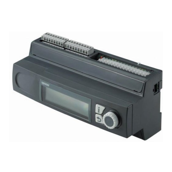
The controller operates the valve actuators and circulation pumps, which in turn affect the supply water temperature to the zone. The temperature in up to four zones can be regulated by the controller. Uponor Smatrix Move PRO Controller X-159 microSD 15VDC 12VDC IN 24VAC IN... - Page 8 Item Description Smatrix Move PRO Sensor Snow & Ice S-158 Mounting socket U P O N O R S M AT R I X M O V E P R O · I N S TA L L AT I O N A N D O P E R AT I O N M A N U A L...
-
Page 9: Accessories
Accessories Functions Uponor offers a wide variety of accessories for use with eating Curve the standard portfolio. The Move PRO controller use a heating curve to calculate the supply temperature setpoint. This requires the zone to be setup as Stand Alone Control or Smatrix Base PRO. - Page 10 To facilitate accurate scheduling, the controller contains The system can be integrated with an Uponor Smatrix a real time clock. If an Uponor Smatrix Base PRO system Base PRO system to enable individual room control in is connected it will act as a time master, pushing the the zone.
-
Page 11: Fi 4 Install Uponor Smatrix Move Pro System
Uponor recommends following the process described • Verify the contents of the package with the packing below to guarantee the best possible installation results. list. See also section 3.3 Uponor Smatrix Move PRO Stage Procedure Page components for identification of components. -
Page 12: Installation Example
Move PRO controller is integrated with an Uponor Smatrix Base PRO system (with outdoor temperature sensor). A connection example of Uponor Smatrix Move PRO See section 5 Install Uponor Smatrix Move PRO Controller (with the heating application installed) controller for more information. - Page 13 See section 5.13 Startup wizard for more information. enabled. See section 7.10 Settings for more information. The controller is connected to an Uponor Smatrix Base PRO system, via the Smatrix Base PRO bus, utilising its components to regulate the zone temperature.
- Page 14 Move PRO controller is integrated with an Uponor requires a return sensor to work properly. Smatrix Base PRO system (with outdoor temperature See section 5 Install Uponor Smatrix Move PRO sensor). controller for more information. See section 5 Install Uponor Smatrix Move PRO SYSTEM SETTINGS IN STARTUP WIZARD controller for more information.
-
Page 15: Install Uponor Smatrix Move Pro Controller
Install Uponor Smatrix Move PRO controller Placement of controller Attach stickers Refer to the installation preparation guidelines (see Attach the stickers from the application package to the section 4.2 Prepare for installation), and use the controller. following guidelines when positioning the controller: •... -
Page 16: Attach Controller To The Wall
• Uponor Smatrix Outdoor S-1XX • Uponor Smatrix Move Sensor Supply/Return S-152 • Uponor Smatrix Move PRO Sensor Room S-155 • Uponor Smatrix Move PRO Sensor Snow S-158 arning Electrical installation and service behind secured 230 V AC covers must be carried... - Page 17 Either directly to the Move PRO controller or connected to the controller. via an integrated Uponor Smatrix Base PRO controller. If a Base PRO controller is integrated to the system, it is a requirement to connect the outdoor temperature sensor...
- Page 18 uPPly sensor eturn sensor The supply sensor needs to be installed in all zones. The return sensor only needs to be installed in zones setup as Meltaway or DHW (domestic hot water). Connect supply sensor to controller Connect return sensor to controller The illustration below shows supply sensors connected to the controller.
- Page 19 Label room sensor oom sensor The room sensor only needs to be installed in zones Label the room sensors, where suitable, with the zone setup as Stand Alone, with Heating Mode setup as numbers they are to control, for example, #02, #03. Outdoor + Indoor comp..
- Page 20 Connect room sensor to controller aution Do not change the jumper setting, The illustration below shows room sensors connected to otherwise the function of the sensor will be the controller. compromised. S-155 Default setting: To connect a room sensor to the controller: 1.
- Page 21 noW sensor The snow sensor only needs to be installed in zones setup as Meltaway. aution Two snow sensors are needed to guarantee the Meltaway function. One of them is used as a ground temperature sensor and the other one as a ground ≥...
- Page 22 Install snow sensor into the ground surface 4. Apply the concrete/asphalt. The following illustrations show how to install the snow sensor into the ground surface. 1. Create a notch for the cable conduit (maximum diameter of 23 mm). It is recommended to use a cable conduit equipped with a cord, in order to make it easier to pull the cable through when installed.
- Page 23 8. Place the snow sensor into the tube. Make sure that To connect a snow sensor to the controller: the cable easily fits in the hole in the bottom. 1. Study the wiring diagram to locate the connection Secure the sensor (in the middle of the sensor) with terminal positions.
- Page 24 Connect snow sensor, used as ground moisture rimary return sensor sensor, to controller The primary return sensor may only need to be installed in zones setup as Meltaway. The illustration below shows the snow sensor, used as ground moisture sensor, connected to the controller. Connect primary return sensor to controller The illustration below shows primary return sensors S-158...
-
Page 25: Connect Valve Actuators To The Controller
Connect valve actuators to the To connect valve actuators to the controller: controller 1. Ensure that the power is disconnected from both the controller and the actuator. The controller can control up to 4 different zones. 2. Remove the terminal cover. The illustration below shows actuators connected to the See section 5.6 Terminal cover for more information. -
Page 26: Connect Circulation Pumps To The Controller
Connect circulation pumps to the To connect circulation pumps to the controller: controller 1. Ensure that the power is disconnected from the controller. The controller can control circulation pumps in up to 4 different zones. 2. Remove the terminal cover. See section 5.6 Terminal cover for more information. -
Page 27: Connect Uponor Smatrix Base Pro Controller
5.10 Connect Uponor Smatrix Base PRO To connect an Uponor Smatrix Base PRO system bus to the controller: controller 1. Ensure that the power is disconnected from all The controller can be connected to an Uponor Smatrix controllers. Base PRO system bus for integration with Base PRO controllers and thermostats. -
Page 28: Connect Modbus Rtu Interface
See separate documentation for more information about Do not use these input terminals, unless BMS integration. instructed to by Uponor technical support. 5.12 Connect the controller to AC power 5.14 Startup wizard The illustration below shows the the controller The controller initiates a startup wizard the first time connected to AC power. - Page 29 1. s avigating tHe startuP Wizard et language Select/change Select the language which is to be used in the controllers menu system. Turn the control wheel to select an option, or to change Language a parameter setting. English Deutsch Espanol Swedish 2.
- Page 30 5 max: 70 the controller. Smatrix Base PRO uses a connected Uponor Smatrix Base PRO system. 5.6 Set a maximum allowed supply temperature. Max. Supply Temp. Zone Setup Stand Alone Control 70˚C...
- Page 31 (selected in the Smatrix Base PRO interface the controller. Smatrix Base PRO uses a connected I-147). Uponor Smatrix Base PRO system. Domestic Hot This setting is only shown if Smatrix Base PRO is Water (DHW) regulates the supply temperature for selected in the Zone Setup menu, and if Outdoor + DHW in the zone.
- Page 32 (selected in the Smatrix Base PRO interface the controller. Smatrix Base PRO uses a connected I-147). Uponor Smatrix Base PRO system. Meltaway uses This setting is only shown if Smatrix Base PRO is snow sensors to keep large areas clear of snow.
- Page 33 (selected in the Smatrix Base PRO interface the controller. Smatrix Base PRO uses a connected I-147). Uponor Smatrix Base PRO system. Meltaway uses This setting is only shown if Smatrix Base PRO is snow sensors to keep large areas clear of snow.
-
Page 34: Pre Heating Concrete Slab (Din 1264-4)
9. a 5.15 Pre heating concrete slab (DIN ssign ontroller to zone 1264-4) If the Move PRO controller is connected to a Smatrix Base PRO system, the connected controllers The controller can be setup to pre heat a concrete slab can be assigned to the different zones. - Page 35 3. s 6. e et tHe date naBle eating Set the date of the system, starting with the day. 6.1 Select Enable to enable pre heating zone 2 in the controller. Date Enter the day Pre-Heating Zone 2 01.06.2016 Disable Enable Date 6.2 Set a maximum allowed calculated supply setpoint.
-
Page 36: Lv 6 Finishing Installation
Finishing installation Make a complete check up of the installation: 1. Make sure all wiring is done correctly and that the wires are thoroughly fastened. 2. Re-attach the terminal covers to the controller. 3. Check the mixing valves. 12 5 Increase the setpoints in each zone to make sure the valves are opening correctly. -
Page 37: Operate The Uponor Smatrix Move Pro Controller
Navigation wheel/ OK button Start up Used for navigating the menu system, selecting options and confirming selections. When starting up, the controller shows the Uponor logo Information button before entering the main menu. Used for showing current zone information such as supply temperature, pump status etc. -
Page 38: Information Button
Information button omestiC ater The following information is shown if the zone is setup as Domestic Hot Water. • Supply Temperature (current supply temperature) • Pump (status) • Mixing valve (status) eltaWay The following information is shown if the zone is setup as Meltaway. -
Page 39: System Overview
System Overview nformation This menu shows information about zone 1. This menu shows the current outdoor temperature, and supply temperatures for enabled zones. Menu tree* z# - s uPPly emPerature Zone 1 Information The current supply temperature is shown. The Zone Setup temperature is measured by the supply temperature Heating Mode... - Page 40 Calculated Supply Setpoint nformation This menu shows information about zone 2. The calculated supply temperature is shown. The setpoint is calculated using the sensor setup selected in Menu tree* Heating Mode. Zone 2 Information Indoor temperature Zone Setup The current indoor temperature for the zone is shown. Heating Mode Heating Curve If the zone is setup as Stand Alone Control the...
- Page 41 Supply temperature nformation This menu shows information about zone 3. The current supply temperature is shown. The temperature is measured by the supply temperature Menu tree* sensor wired to the controller. Zone 3 Information Calculated Supply Setpoint Zone Setup The calculated supply temperature is shown. The Heating Mode setpoint is calculated using the sensor setup selected in Heating Curve...
- Page 42 Heating Curve Ground Temperature This menu shows the heating curve, and max/min The current temperature in the ground around the snow supply temperature limits, for the zone. sensor is shown. This information is only shown if Zone Setup is set to This information is only shown if Zone Setup is set to Stand Alone Control or Smatrix Base PRO.
- Page 43 Heating Curve nformation This menu shows information about zone 4. This menu shows the heating curve, and max/min supply temperature limits, for the zone. Menu tree* This information is only shown if Zone Setup is set to Zone 4 Information Stand Alone Control or Smatrix Base PRO.
- Page 44 Return temperature ontroller nformation This menu shows information about the controller. The current return temperature is shown. This information is only shown if Zone Setup is set to Menu tree Meltaway. Controller Information Ground Temperature Language About... The current temperature in the ground around the snow sensor is shown.
-
Page 45: Alarms
Alarms CknoWledge all alarms This menu enables to acknowledge all active alarms. This menu shows the current active alarms and the To acknowledge all active alarms: alarm history. A possibility of acknowleding all alarms and reseting the alarm histroy is also available. 1. -
Page 46: Settings
7.10 Settings T Outdoor Fallback In this menu the fallback temperature for the outdoor In this menu installer settings, enabled zone settings, temperature sensor is set. This value will be used if the and controller settings can be changed (when the connection to the outdoor temperature sensor is lost. - Page 47 Change lock code Restore factory settings The standard lock code which is used to block a user This menu enables all parameter settings in the from changing parameter settings, can be changed in controller to be reset to the factory default settings. this menu.
- Page 48 New backup ettings In this menu parameter settings for zone 1 can be set or This menu enables the controller to save a backup of all changed. parameter settings to the microSD-card. To save from a backup: Menu tree* 1. Make sure a microSD-card, where the backup is to Zone 1 Settings be saved, into the controller.
- Page 49 MIN. SUPPLY TEMP. DEVIATION ALARM LIMIT In this menu the minimum allowed supply temperature In this menu the deviation alarm limit for the supply for the zone can be set. The supply temperature is not temperature in the zone is set. If the difference between allowed to fall below this value.
- Page 50 Indoor Temp. Settings INDOOR SETPOINT INFLUENCE (LOWER) This menu enables access to settings related to the In this menu the indoor setpoint influence (lower) is set. room temperature sensor in the zone. If the measured indoor temperature is higher than the indoor temperature setpoint, the supply temperature This menu and its submenus are only shown if Heating sepoint will be lowered using this value.
- Page 51 Comf. - ECO To edit/create the ECO-Comf Schedule: This menu enables access to settings related to the 1. Select ECO-Comf Schedule. controller Comfort/ECO modes. 2. Press the navigation wheel to confirm selection. This menu and its submenus are only shown if Zone The current schedule is showing.
- Page 52 Heating Curve Manual Operation This menu enables access to heating curve settings for This menu enables access to manual operation mode in the zone. Settings such as the slope (Setting) and offset the zone. of the heating curve. When manual operation mode is activated, access to This menu is only shown if Zone Setup is set to Stand manual control (override) of the circulation pump and Alone Control for the zone...
- Page 53 MIXING VALVE EXERCISE DAY OF THE WEEK In this menu the mixing valve can be overriden opened In this menu the day of the week for pump exercise is or closed manually. set. To override the mixing valve setting: This menu is only shown if Pump Exercise is set to Pump Exercise.
- Page 54 Mixing Valve ACTUATOR RUNNING TIME This menu enables access to mixing valve settings in the In this menu the actuator running time for the mixing zone. valve regulation is set. To set the actuator running time: MENU TREE 1. Select Actuator running time. Mixing Valve 2.
- Page 55 Seasonal Shut Off VALVE CLOSE This menu enables access to seasonal shut off settings In this menu a function to close the mixing valve, when in the zone. requirements are met, is enabled. MENU TREE* To enable the function: 1. Select Valve Close. Seasonal Shut Off Pump Stop 2.
- Page 56 T. OUTDOOR SETPOINT SHUT OFF INDOOR TEMP. In this menu the outdoor temperature setpoint for In this menu the function to stop the circulation pump, stopping the circulation pump, and/or closing the and/or when to close the mixing valve, at an indoor mixing valve, in the zone is set.
- Page 57 CALCULATED SUPPLY SETPOINT ettings In this menu parameter settings for zone 2 can be set or In this menu the calculated supply setpoint for the zone changed. can be overidden. This temperature is used as setpoint for the supply temperature. Menu tree* This menu is only shown if Zone Setup is set to Stand Zone 2 Settings...
- Page 58 MAX. SUPPLY TEMP. OVERHEATING ALARM LIMIT In this menu the maximum allowed supply temperature In this menu the overheating alarm limit for domestic for the zone can be set. The supply temperature is not hot water production is set. If the supply temperature allowed to rise above this value.
- Page 59 DEVIATION ALARM LIMIT Indoor Temp. Settings In this menu the deviation alarm limit for the supply This menu enables access to settings related to the temperature in the zone is set. If the difference between room temperature sensor in the zone. the measured and the calculated supply temperatures This menu and its submenus are only shown if Heating are higher than the set limit during the time set in...
- Page 60 CALCULATED INDOOR SETPOINT INDOOR SETPOINT INFLUENCE (UPPER) This menu shows the calculated indoor setpoint for the In this menu the indoor setpoint influence (upper) zone. is set. If the measured indoor temperature is lower than the indoor temperature setpoint, the supply This information is only shown if Zone Setup is set to temperature sepoint will be increased using this value.
- Page 61 DHW Circ Return Settings BOOSTPOWER This menu enables access to settings related to the In this menu the boost power for domestic hot water return temperature sensor. production is set. The parameter is used to adjust the calculated supply temperature, if the difference This menu is only shown if Zone Setup is set to between the supply and return temperatures is to large.
- Page 62 Comf. - ECO To edit/create the ECO-Comf Schedule: This menu enables access to settings related to the 1. Select ECO-Comf Schedule. controller Comfort/ECO modes. 2. Press the navigation wheel to confirm selection. This menu and its submenus are only shown if Zone The current schedule is showing.
- Page 63 Heating Curve Manual Operation This menu enables access to heating curve settings for This menu enables access to manual operation mode in the zone. Settings such as the slope (Setting) and offset the zone. of the heating curve. When manual operation mode is activated, access to This menu is only shown if Zone Setup is set to Stand manual control (override) of the circulation pump and Alone Control for the zone...
- Page 64 MIXING VALVE Pump In this menu the mixing valve can be overriden opened This menu enables access to pump settings in the zone. or closed manually. This menu is only shown if Zone Setup is set to Stand Alone Control or Domestic Hot Water for the zone. To override the mixing valve setting: 1.
- Page 65 EXERCISE HOUR Mixing Valve In this menu the hour of the day for pump exercise is This menu enables access to mixing valve settings in the set. zone. This menu is only shown if Pump Exercise is set to MENU TREE Pump Exercise.
- Page 66 Seasonal Shut Off I-TIME In this menu the I-time for the mixing valve regulation This menu enables access to seasonal shut off settings is set. in the zone. To set the I-time: This menu is only shown if Zone Setup is set to Stand Alone Control or Smatrix Base PRO.
- Page 67 VALVE CLOSE T. OUTDOOR SETPOINT In this menu a function to close the mixing valve, when In this menu the outdoor temperature setpoint for requirements are met, is enabled. stopping the circulation pump, and/or closing the mixing valve, in the zone is set. To enable the function: This menu is only shown if Shut Off Outdoor Temp.
- Page 68 SHUT OFF INDOOR TEMP. ettings In this menu parameter settings for zone 3 can be set or In this menu the function to stop the circulation pump, changed. and/or when to close the mixing valve, at an indoor temperature setpoint is enabled/disabled for the zone. Menu tree* This menu is only shown if Pump Stop and/or Valve Zone 3 Settings...
- Page 69 CALCULATED SUPPLY SETPOINT MAX. SUPPLY TEMP. In this menu the calculated supply setpoint for the zone In this menu the maximum allowed supply temperature can be overidden. This temperature is used as setpoint for the zone can be set. The supply temperature is not for the supply temperature.
- Page 70 MIN. SUPPLY TEMP. (IDLE STATUS) DEVIATION ALARM LIMIT In this menu the minimum available supply temperature In this menu the deviation alarm limit for the supply for the zone, while meltaway status is IDLE, can be set. temperature in the zone is set. If the difference between The supply temperature is not allowed to fall below this the measured and the calculated supply temperatures value.
- Page 71 Indoor Temp. Settings INDOOR SETPOINT INFLUENCE (LOWER) This menu enables access to settings related to the In this menu the indoor setpoint influence (lower) is set. room temperature sensor in the zone. If the measured indoor temperature is higher than the indoor temperature setpoint, the supply temperature This menu and its submenus are only shown if Heating sepoint will be lowered using this value.
- Page 72 Comf. - ECO To edit/create the ECO-Comf Schedule: This menu enables access to settings related to the 1. Select ECO-Comf Schedule. controller Comfort/ECO modes. 2. Press the navigation wheel to confirm selection. This menu and its submenus are only shown if Zone The current schedule is showing.
- Page 73 Heating Curve Meltaway Curve (IDLE Status) This menu enables access to heating curve settings for This menu enables access to meltaway heating curve the zone. Settings such as the slope (Setting) and offset settings for the zone while in IDLE status. Settings of the heating curve.
- Page 74 Return Temperature Enter Stop State Conditions This menu enables access to settings related to the This menu enables access to parameters deciding when return temperature sensor. to switch the meltaway state in the zone between IDLE and STOP. This menu is only shown if Zone Setup is set to Meltaway for the zone.
- Page 75 Enter Idle State Conditions DELAY (HOURS) This menu enables access to parameters used when to In this menu the number of delay hours, used to switch switch the meltaway state in the zone to and from IDLE. meltaway state from STOP to IDLE, is set. The zone switches from STOP to IDLE state when the To set the delay: measured outdoor temperature is lower than the value...
- Page 76 Enter Melting State Conditions OUTDOOR TEMP. OFFSET This menu enables access to parameters used when In this menu the outdoor temperature offset, used to to switch the meltaway state in the zone to and from switch meltaway state from IDLE to MELTING, is set. MELTING.
- Page 77 Manual Operation MIXING VALVE This menu enables access to manual operation mode in In this menu the mixing valve can be overriden opened the zone. or closed manually. When manual operation mode is activated, access to To override the mixing valve setting: manual control (override) of the circulation pump and 1.
- Page 78 Pump EXERCISE HOUR This menu enables access to pump settings in the zone. In this menu the hour of the day for pump exercise is set. This menu is only shown if Zone Setup is set to Stand Alone Control or Meltaway for the zone. This menu is only shown if Pump Exercise is set to Pump Exercise.
- Page 79 Mixing Valve I-TIME This menu enables access to mixing valve settings in the In this menu the I-time for the mixing valve regulation zone. is set. To set the I-time: MENU TREE 1. Select I-time. Mixing Valve 2. Press the navigation wheel to confirm selection. P-area 3.
- Page 80 Seasonal Shut Off VALVE CLOSE This menu enables access to seasonal shut off settings In this menu a function to close the mixing valve, when in the zone. requirements are met, is enabled. This menu is only shown if Zone Setup is set to Stand To enable the function: Alone Control or Smatrix Base PRO.
- Page 81 T. OUTDOOR SETPOINT SHUT OFF INDOOR TEMP. In this menu the outdoor temperature setpoint for In this menu the function to stop the circulation pump, stopping the circulation pump, and/or closing the and/or when to close the mixing valve, at an indoor mixing valve, in the zone is set.
- Page 82 Automatic Freeze Protection ettings In this menu parameter settings for zone 3 can be set or This menu decides when to activate automatic freeze changed. protection during meltaway in the zone. The controller will kepp the return temperature between the low and Menu tree* high thersholds.
- Page 83 CALCULATED SUPPLY SETPOINT MAX. SUPPLY TEMP. In this menu the calculated supply setpoint for the zone In this menu the maximum allowed supply temperature can be overidden. This temperature is used as setpoint for the zone can be set. The supply temperature is not for the supply temperature.
- Page 84 MIN. SUPPLY TEMP. (IDLE STATUS) DEVIATION ALARM LIMIT In this menu the minimum available supply temperature In this menu the deviation alarm limit for the supply for the zone, while meltaway status is IDLE, can be set. temperature in the zone is set. If the difference between The supply temperature is not allowed to fall below this the measured and the calculated supply temperatures value.
- Page 85 Indoor Temp. Settings INDOOR SETPOINT INFLUENCE (LOWER) This menu enables access to settings related to the In this menu the indoor setpoint influence (lower) is set. room temperature sensor in the zone. If the measured indoor temperature is higher than the indoor temperature setpoint, the supply temperature This menu and its submenus are only shown if Heating sepoint will be lowered using this value.
- Page 86 Comf. - ECO To edit/create the ECO-Comf Schedule: This menu enables access to settings related to the 1. Select ECO-Comf Schedule. controller Comfort/ECO modes. 2. Press the navigation wheel to confirm selection. This menu and its submenus are only shown if Zone The current schedule is showing.
- Page 87 Heating Curve Meltaway Curve (IDLE Status) This menu enables access to heating curve settings for This menu enables access to meltaway heating curve the zone. Settings such as the slope (Setting) and offset settings for the zone while in IDLE status. Settings of the heating curve.
- Page 88 Return Temperature Enter Stop State Conditions This menu enables access to settings related to the This menu enables access to parameters deciding when return temperature sensor. to switch the meltaway state in the zone between IDLE and STOP. This menu is only shown if Zone Setup is set to Meltaway for the zone.
- Page 89 Enter Idle State Conditions DELAY (HOURS) This menu enables access to parameters used when to In this menu the number of delay hours, used to switch switch the meltaway state in the zone to and from IDLE. meltaway state from STOP to IDLE, is set. The zone switches from STOP to IDLE state when the To set the delay: measured outdoor temperature is lower than the value...
- Page 90 Enter Melting State Conditions GROUND TEMPERATURE LIMIT This menu enables access to parameters used when In this menu the ground temperature limit, used to to switch the meltaway state in the zone to and from switch meltaway state between IDLE to MELTING , is MELTING.
- Page 91 OUTDOOR TEMPERATURE LOW LIMIT Manual Operation In this menu the lower outdoor temperature limit, used This menu enables access to manual operation mode in to switch meltaway state from IDLE to MELTING, is set. the zone. When manual operation mode is activated, access to To set the lower outdoor temperature limit: manual control (override) of the circulation pump and 1.
- Page 92 MIXING VALVE Pump In this menu the mixing valve can be overriden opened This menu enables access to pump settings in the zone. or closed manually. This menu is only shown if Zone Setup is set to Stand Alone Control or Meltaway for the zone. To override the mixing valve setting: 1.
- Page 93 EXERCISE HOUR Mixing Valve In this menu the hour of the day for pump exercise is This menu enables access to mixing valve settings in the set. zone. This menu is only shown if Pump Exercise is set to MENU TREE Pump Exercise.
- Page 94 I-TIME Seasonal Shut Off In this menu the I-time for the mixing valve regulation This menu enables access to seasonal shut off settings is set. in the zone. This menu is only shown if Zone Setup is set to Stand To set the I-time: Alone Control or Smatrix Base PRO.
- Page 95 VALVE CLOSE T. OUTDOOR SETPOINT In this menu a function to close the mixing valve, when In this menu the outdoor temperature setpoint for requirements are met, is enabled. stopping the circulation pump, and/or closing the mixing valve, in the zone is set. To enable the function: This menu is only shown if Shut Off Outdoor Temp.
- Page 96 SHUT OFF INDOOR TEMP. Automatic Freeze Protection In this menu the function to stop the circulation pump, This menu decides when to activate automatic freeze and/or when to close the mixing valve, at an indoor protection during meltaway in the zone. The controller will kepp the return temperature between the low and temperature setpoint is enabled/disabled for the zone.
- Page 97 Language ontroller ettings In this menu parameter settings for the controller can be In this menu the language of the system is set. set or changed. To set the language: Menu tree 1. Select Language. Controller Settings 2. Press the navigation wheel to confirm selection. Time 3.
-
Page 98: Pre Heating Info
7.11 Pre Heating Info nformation This menu shows information about zone 1. This menu shows information about the system, enabled zones and the controller (when the operating mode is Menu tree set to Pre Heating in the startup wizard). Zone 1 Information Menu tree* Supply temperature State... - Page 99 nformation nformation This menu shows information about zone 2. This menu shows information about zone 3. Menu tree Menu tree Zone 2 Information Zone 3 Information Supply temperature Supply temperature State State Time Left Time Left Supply temperature Supply temperature The current supply temperature is shown.
-
Page 100: Pre Heating Settings
nformation ontroller nformation This menu shows information about zone 4. This menu shows information about the controller. Menu tree Menu tree Zone 4 Information Controller Information Supply temperature Language State About... Time Left Language Supply temperature This menu show the set display language for the controller. - Page 101 ENTERING A MENU WHEN LOCK CODE IS ENABLED nstaller ettings In this menu lock codes (to gain access to locked To enter a lock code: parameter settings) can be set or changed, factory 1. Select the parameter. settings can be restored, backup of controller parameter settings can be managed, or the setup wizard can be 2.
- Page 102 Display settings New backup This menu enables display settings, such as contrast, This menu enables the controller to save a backup of all and it also shows the version number of the display parameter settings to the microSD-card. software. To save from a backup: To set the display contrast: 1.
- Page 103 P-area ettings In this menu parameter settings for zone 1 can be set or In this menu the P-area for the mixing valve regulation changed. is set. To set the P-area: Menu tree 1. Select P-area. Zone 1 Settings 2. Press the navigation wheel to confirm selection. Z1 Max.
- Page 104 P-area ettings In this menu parameter settings for zone 2 can be set or In this menu the P-area for the mixing valve regulation changed. is set. To set the P-area: Menu tree 1. Select P-area. Zone 2 Settings 2. Press the navigation wheel to confirm selection. Z2 Max.
- Page 105 P-area ettings In this menu parameter settings for zone 3 can be set or In this menu the P-area for the mixing valve regulation changed. is set. To set the P-area: Menu tree 1. Select P-area. Zone 3 Settings 2. Press the navigation wheel to confirm selection. Z3 Max.
- Page 106 P-area ettings In this menu parameter settings for zone 4 can be set or In this menu the P-area for the mixing valve regulation changed. is set. To set the P-area: Menu tree 1. Select P-area. Zone 4 Settings 2. Press the navigation wheel to confirm selection. Z4 Max.
- Page 107 Language ontroller ettings In this menu parameter settings for the controller can be In this menu the language of the system is set. set or changed. To set the language: Menu tree 1. Select Language. Controller Settings 2. Press the navigation wheel to confirm selection. Time 3.
-
Page 108: Menu Tree
7.13 Menu tree N O T E ! Parts of the menu tree may only be visible in the Move PRO controller depending on its current configuration. tandard Perating System Overview Information System information Time Date Outdoor Temperature Zone 1 Information Zone Setup Heating Mode Heating Curve... - Page 109 Zone 4 Information Zone Setup Heating Mode Heating Curve Supply temperature Calculated Supply Setpoint Indoor temperature ECO-Comf Status Meltaway Curve Return temperature Ground Temperature Ground Moisture Primary Return Temperature Status Mixing Valve Pump Controller Information Language About... Alarms Active alarms Alarm history Acknowledge all alarms Reset alarm history...
- Page 110 Heating Curve Setting Offset Heating Curve Manual Operation Manual Mode Pump Mixing valve Pump Pump Exercise Exercise Day of the Week Exercise Hour Exercise Min Mixing Valve P-area I-time Actuator running time Seasonal Shut Off Pump Stop Valve Close Shut Off Outdoor Temp. T.
- Page 111 Manual Operation Manual Mode Pump Mixing valve Pump Pump Exercise Exercise Day of the Week Exercise Hour Exercise Min Mixing Valve P-area I-time Actuator running time Seasonal Shut Off Pump Stop Valve Close Shut Off Outdoor Temp. T. Outdoor Setpoint T.
- Page 112 Meltaway Curve (IDLE Status) Setting Offset Heating Curve Return Temperature Max. Supply-Return Diff. Enter Stop State Conditions Outdoor Temperature Delay (days) Enter Idle State Conditions Outdoor Temperature Delay (hours) Delay Surface Dry Enter Melting State Conditions Ground Temperature Limit Outdoor Temp. Offset Outdoor Temperature Low Limit Min.
- Page 113 Zone 4 Settings Supply Temp. Settings Calculated Supply Setpoint Melting Supply Setpoint Min. Supply Temp. Max. Supply Temp. Heating Curve Meltaway IDLE Supply Setpoint Min. Supply Temp. (IDLE Status) Max. Supply Temp. (IDLE Status) Deviation alarm limit Deviation alarm delay Indoor Temp.
- Page 114 Mixing Valve P-area I-time Actuator running time Seasonal Shut Off Pump Stop Valve Close Shut Off Outdoor Temp. T. Outdoor Setpoint T. Outdoor Delay Shut Off Indoor Temp. T. Indoor Delay Automatic Freeze Protection Primary return Temp. Low Primary return Temp. High Controller Settings Time Date...
- Page 115 Pre Heating Settings Installer Settings Lock code Change lock code Display settings Restore factory settings Restore backup New backup Restart wizard Zone 1 Settings Z1 Max. Calc. Supply Setpoint Frost Protection Setpoint P-area I-time Actuator running time Zone 2 Settings Z2 Max.
-
Page 116: Maintenance
Maintenance The maintenance of Uponor Smatrix Move PRO includes Corrective maintenance the following: allBaCk mode • Manual preventive maintenance If a sensor is malfunctioning or not detected, the • Automatic preventive maintenance controller triggers an alarm and executes the fallback mode to maintain the temperature in the zone until the •... -
Page 117: Troubleshooting
Troubleshooting The table below shows problems and alarms that can occur with Uponor Smatrix Move PRO and describes solutions. A common cause of a problem though may be due to wrongly installed loops or mixed up thermostats. Problem Indication Probable cause... -
Page 118: Troubleshooting After Installation
Troubleshooting after installation Problem Indication Probable cause Solutions The system does The controller display is off There is no AC power to the controller 1. Check that the controller is connected not start to AC power 2. Check the wiring 3. -
Page 119: Technical Data
BMS interface MODBUS-RTU (RS-232) RJ45 Uponor Smatrix Base PRO bus Galvanically isolated Terminals: –, A, B U P O N O R S M AT R I X M O V E P R O · I N S TA L L AT I O N A N D O P E R AT I O N M A N U A L... -
Page 120: Technical Specifications
Mixing valve output connection terminals Battery and transformer input connection terminals microSD BMS, MODBUS-RTU (RS-232), connection Uponor Smatrix Base PRO bus connection terminals Snow and ice sensor output connection terminals Circulation pump output connection terminals Power connection connection terminal Fuse (125 mA) -
Page 121: Wiring Diagram, Uponor Smatrix Move Pro Controller
10.4 Wiring diagram, Uponor Smatrix Move PRO controller 15VDC 12VDC IN 24VAC IN 1 2 3 4 5 6 7 8 9 10 11 12 13 14 52 53 54 55 56 microSD 125 mA 75 76 77 78 79 80 230 V ±10%... -
Page 122: Dimensions
10.5 Dimensions ontroller X-159 90 mm 45 mm 214 mm oom temPerature sensor 80 mm S-155 60 mm 30 mm noW sensor S-158 63.5 mm 60 mm U P O N O R S M AT R I X M O V E P R O · I N S TA L L AT I O N A N D O P E R AT I O N M A N U A L 1 2 2... -
Page 123: Installation Report
11 Installation report Zone 1 Zone 2 Zone 3 Zone 4 Setup Sensors Supply temperature sensor Indoor temperature sensor Outdoor temperature sensor Mixing Valve Circulation pump Supply temperature sensor Mixing valve Circulation pump Smatrix Base PRO controller U P O N O R S M AT R I X M O V E P R O · I N S TA L L AT I O N A N D O P E R AT I O N M A N U A L 1 2 3... - Page 124 Zone 1 Zone 2 Zone 3 Zone 4 Setup Sensors Supply temperature sensor Return temperature sensor Outdoor temperature sensor Ground temperature sensor Moisture sensor Primary return sensor Mixing valve Circulation pump Snow and ice sensor Supply temperature sensor Return temperature sensor Mixing valve Circulation pump U P O N O R S M AT R I X M O V E P R O ·...
- Page 125 U P O N O R S M AT R I X M O V E P R O · I N S TA L L AT I O N A N D O P E R AT I O N M A N U A L 1 2 5...
- Page 126 Uponor Corporation www.uponor.com Uponor reserves the right to make changes, without prior notification, to the specification of incorporated components in line with its policy of continuous improvement and development.
Need help?
Do you have a question about the Smatrix Move PRO and is the answer not in the manual?
Questions and answers