Uponor Smatrix Base PULSE Installation And Operation Manual
Hide thumbs
Also See for Smatrix Base PULSE:
- Installation and operation manual (120 pages) ,
- Quick manual (13 pages) ,
- Quick manual (4 pages)
Table of Contents
Advertisement
Quick Links
Download this manual
See also:
Quick Manual
Advertisement
Chapters
Table of Contents
Troubleshooting

Related Manuals for Uponor Smatrix Base PULSE


Summary of Contents for Uponor Smatrix Base PULSE
- Page 1 Uponor Smatrix Base PULSE Installation and operation manual CD0000131...
-
Page 2: Table Of Contents
11.2 Communication module LEDs..........65 11.3 Factory reset the communication module......65 Install Uponor Smatrix Base PULSE room controller..20 Placement of room controller..........20 Operate Uponor Smatrix Base thermostats..... 66 Connect optional slave module..........21 Connect optional star module..........21 12.1... - Page 3 Technical data..............90 15.1 Technical data............... 90 15.2 Cable specifications.............. 91 15.3 Uponor Smatrix Base PULSE room controller layout... 92 15.4 Wiring diagram..............92 15.5 Dimensions................93 Uponor Smatrix Base PULSE Installation and operation manual...
-
Page 4: Copyright And Disclaimer
You agree to comply with all copyright laws worldwide in your use of the manual. Modification or use of any of the contents of the manual for any other purpose is a violation of Uponor’s copyright, trademark and other proprietary rights. -
Page 5: Preface
This installation and operation manual describes how to install and Power operate the components of the system. Warning! The Uponor system uses 50 Hz, 230 V AC power. In 2.1 Safety instructions case of emergency, immediately disconnect the power. Warnings used in this manual... -
Page 6: Uponor Smatrix Base Pulse System Description
Uponor Smatrix Wave is controlled by different types of thermostats. Designed for maximum comfort, the thermostats communicate with the room controller by a wired communication protocol. It is possible to mix the different types of Uponor Smatrix Base thermostats in the same installation. CD0000132... -
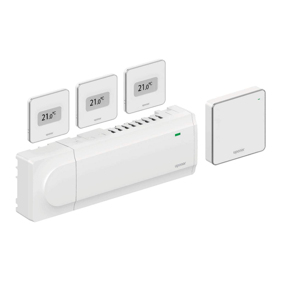
Page 7: Uponor Smatrix Base Pulse Components
2-way communication with up to six room thermostats. humidity sensor and operative sensor • Heating/cooling function (advanced), and/or Comfort/ECO mode switched by dry contact, public thermostat, or Uponor Smatrix Uponor Smatrix Base T-148 Programmable digital thermostat with relative PULSE app (requires communication module). - Page 8 The thermostats communicate with the controller by a wired communication protocol and are used either individually or in combination with each other. Communication module The following Uponor Smatrix thermostats can be used in the system: Note • Uponor Smatrix Base T-141, Page 8 •...
- Page 9 The thermostat temperature settings are adjusted using the dial. • Optional external temperature sensor can be connected to the Maximum/minimum temperatures can only be set using the Uponor thermostat. Floor temperature limitation settings (maximum and Smatrix PULSE app (requires communication module). The 21 °C minimum) are only available using the Uponor Smatrix PULSE position is marked on the dial.
- Page 10 • Setpoint range is 5 – 35 °C (maximum and minimum setting may be limited by other system settings). Uponor recommends only using this thermostat in systems without a • Room temperature regulation with use of optional external communication module. The scheduling function in the thermostat is temperature sensors.
- Page 11 • Easy plug in installation on existing room controller, no additional wiring needed. Uponor actuators are mounted on top of the manifold valves and is operated using either on/off signals or pulse width modulation (PWM) • Register up to six extra thermostats to the system.
-
Page 12: Accessories
As soon as the temperature measured at a thermostat is lower (heating mode) or higher (cooling mode) than the setpoint Uponor offers a wide variety of accessories for use with the standard portfolio. temperature, a demand to change the room temperature is created and sent to the room controller. - Page 13 When switching back to heating, the value is according to customer needs. Temperatures can be adjusted with used to reduce the setpoint. thermostats located in each room, or if installed with the Uponor Smatrix PULSE app (requires communication module). Heating fallback...
- Page 14 Each room controller has a pump relay, to which one circulation pump can be connected. Default operating mode of the circulation pump is set to Individual mode. Use the Uponor Smatrix PULSE app (requires communication module) to change the setting if needed.
-
Page 15: Install Uponor Smatrix Base Pulse
AC wall socket, or if required by local regulations, to a junction Prepare for installation, Page 15 box, connected to the mains power. Install Uponor Smatrix Base PULSE room controller, Page 20 • Ensure that installed Uponor Smatrix components are protected Install communication module, Page 23 from running or dripping water. -
Page 16: Installation Example
See Wiring diagram, Page 92, for more information Slave Module (six extra channels and three extra bus connectors), and Uponor Smatrix Base PULSE Star Module (eight extra bus connectors), using system devices (S) and thermostats (T) as shown in figure. - Page 17 Room sensor T-141: Multiple Uponor Smatrix room controllers can be linked together • Set the value using the Uponor Smatrix PULSE app (requires by assigning one room controller to be master and the rest to be communication module). sub room controllers.
-
Page 18: Network Connectivity
(smart phone/tablet). Note API connection only supports external control. The room controller (C) can be setup and controlled using the Uponor Smatrix PULSE app (A) and communication module (B) through different connection methods. Uponor Smatrix Base PULSE... - Page 19 The external system (G) uses an API to communicate with Uponor cloud services (F). • Uponor cloud services (F) connect to the communication module (B) via the local internet connected Wi-Fi router (E). • The communication module (B) and Wi-Fi router (E) are connected using either Wi-Fi or efternet.
-
Page 20: Install Uponor Smatrix Base Pulse Room Controller
5 Install Uponor Smatrix Base PULSE room controller 5.1 Placement of room controller Attaching/detaching components Caution! Use the following guidelines when positioning the room controller: The transformer module is heavy and might detach if the • Position the room controller close to the manifold, just above if room controller is held upside down without the cover on. -
Page 21: Connect Optional Slave Module
Repeat for the other side. the room controller and star module. Remove the slave module. Use caution not to bend the Tighten the screws fixing the wires in the connectors. connection pins. Uponor Smatrix Base PULSE Installation and operation manual... -
Page 22: Attach Room Controller To The Wall
Make sure the room controller cannot slide off the DIN rail if mounting it in any other position than horizontal. Fasten the DIN rail to the wall using the screws and wall plugs. Snap the room controller to the DIN rail. Uponor Smatrix Base PULSE Installation and operation manual... -
Page 23: Install Communication Module
Attach the communication module back mount to the wall box. Using adhesive tape 90 x 25 SI0000147 Separate the communication module from its removable back mount. SI0000150 Attach the communication module back mount to the wall using adhesive tape. Uponor Smatrix Base PULSE Installation and operation manual... - Page 24 B Breakout plastic, mostly used when attached to a wall. Remove communication module is placed in a location with poor Wi-Fi the breakout plastic before mounting the back mount to the wall. reception. Uponor Smatrix Base PULSE Installation and operation manual...
-
Page 25: Connect Actuators To Room Controller
A2 connection terminals on the relay. Each thermostat can control one or more channels. To Lead the cables from the relay through cable entries in the simplify installation and maintenance, Uponor bottom of the room controller frame. recommends that actuators controlled by the same Press the white button on the quick connector, using a thin thermostat shall be wired in sequence to the channels. - Page 26 Lead the cables through cable entries on the top of the room controller frame. Insert the four wires (A,B, + and -) into the connector on the room controller. Tighten the screws fixing the wires in the connector. Uponor Smatrix Base PULSE Installation and operation manual...
- Page 27 Lead the cables through cable entries in the star module frame. Insert the four wires (A,B, + and -) into the connector on the electrical card. Tighten the screws fixing the wires in the connector. Uponor Smatrix Base PULSE Installation and operation manual...
- Page 28 Tighten the screws fixing the wires in the connector. Tighten the screws fixing the wires in the connector. Insert the connectors on the input pegs on the thermostat. Insert the connectors on the input pegs on the thermostat. Uponor Smatrix Base PULSE Installation and operation manual...
-
Page 29: Connect Input To Room Controller Gpi
The room controller is equipped with a General Purpose Input (GPI) connection terminal. Set the kind of input signal to be expected. When the signal is closed the function is activated. Uponor Smatrix Base PULSE Installation and operation manual... -
Page 30: Connect Output To Room Controller Relays
Connect the cable to the room controller connector labelled GPI. • Connecting external Comfort/ECO switch to the system (public thermostat system device, or GPI), disables Forced ECO in the Uponor Smatrix PULSE 5.10 Connect output to room app. controller relays •... - Page 31 2) Function only available when Pump management is set to Individual, a dry contact to switch off and on the power connection otherwise "Not used" is shown in the Uponor Smatrix PULSE app. to the pump. 3) Function only available when cooling is activated.
- Page 32 Route the cable from/to the heating/cooling relay via a cable enclosure. entry. Close and secure the lid to the optional connections Connect the heating/cooling relay to the connection labelled compartment. Relay 2 (BOILER). Uponor Smatrix Base PULSE Installation and operation manual...
- Page 33 It will stop when the minimum run time of 30 minutes has finalized and when the relative humidity has decreased below the defined RH setpoint - deadzone. Uponor Smatrix Base PULSE Installation and operation manual...
- Page 34 Relay function Relay function The relay is closed when the Uponor Smatrix system is set to ECO. The ventilation must be setup to lower its speed when the input is ECO mode is activated when the relay is closed.
-
Page 35: Connect Room Controller To Ac Power
230 V AC covers must be carried out under the supervision of a qualified electrician. Connect the power cable to a 230 V AC wall socket, or if required by local regulations, to a junction box. Uponor Smatrix Base PULSE Installation and operation manual... -
Page 36: Install Uponor Smatrix Base Room Thermostat
6 Install Uponor Smatrix Base room thermostat 6.1 Uponor Smatrix Base T-141 Connect communication cable to thermostat Placement of thermostat 1.3–1.5 m SI0000032 Press the push buttons on the connection terminal on the back of the thermostat. While pressing the push buttons, insert each of the four wires... - Page 37 Attach the thermostat to the wall using the screw and wall plug. Register thermostat to room controller SI0000130 Sensor frame not supplied by Uponor. 1. Enter registration mode Attach the thermostat to the wall using the wall bracket, screws and wall plugs.
-
Page 38: Uponor Smatrix Base T-143
Connect external sensor to thermostat LEDs turn off to end registration and return to run mode. To unregister already registered thermostats, see Unregister room controller channels, Page 62. 6.2 Uponor Smatrix Base T-143 Placement of thermostat 1.3–1.5 m SI0000135 Insert the two wires from the sensor cable (non polarized) into the removable connector. - Page 39 + and -) on the thermostat. channel 1 (or the first unregistered channel) flashes red. Tighten the screws fixing the wires in the connector. Insert the connectors on the input pegs on the thermostat. Uponor Smatrix Base PULSE Installation and operation manual...
- Page 40 To unregister already registered thermostats, see Unregister room controller channels, Page 62. Optional: To activate tamper alarm for the thermostat, set the Disable timer switch to Comfort mode ( ) before registering the thermostat. Uponor Smatrix Base PULSE Installation and operation manual...
-
Page 41: Uponor Smatrix Base T-144
6.3 Uponor Smatrix Base T-144 Connect communication cable to thermostat Placement of thermostat A B + - 1.3–1.5 m SD0000002 • Select an indoor wall and a position 1.3 m to 1.5 m above the SI0000031 floor. Insert the four wires into the connectors marked (A,B, + and -) on the thermostat. -
Page 42: Uponor Smatrix Base T-145
2. Select a channel 6.4 Uponor Smatrix Base T-145 Placement of thermostat SI0000139 1.3–1.5 m Use buttons < or > to move the pointer (LED flashes red) to a preferred channel. 3. Lock selected channel SD0000002 • Select an indoor wall and a position 1.3 m to 1.5 m above the floor. -
Page 43: Insert The Four Wires Into The Removable Connectors Marked
Press the OK button to select the channel for registration. The LED for the selected channel starts flashing green. Select all channels to be registered to the thermostat and continue to the next step. Uponor Smatrix Base PULSE Installation and operation manual... -
Page 44: Uponor Smatrix Base T-146
LEDs turn off to end registration and return to run mode. Connect external sensor to thermostat To unregister already registered thermostats, see Unregister room controller channels, Page 62. 6.5 Uponor Smatrix Base T-146 Placement of thermostat 1.3–1.5 m SI0000135 Insert the two wires from the sensor cable (non polarized) into the removable connector. - Page 45 The thermostat is delivered in a kit with screws, wall plugs, and a wall bracket, presenting several options of attaching the thermostat to the SI0000066 wall. Use buttons < or > to move the pointer (LED flashes red) to a preferred channel. Uponor Smatrix Base PULSE Installation and operation manual...
-
Page 46: Uponor Smatrix Base T-148
3. Lock selected channel 6.6 Uponor Smatrix Base T-148 Placement of thermostat SI0000071 Note It is recommended to register all channels to the thermostat at the same time. 1.3–1.5 m Press the OK button to select the channel for registration. The LED for the selected channel starts flashing green. - Page 47 Insert the connectors on the input pegs on the thermostat. Use buttons - or + to change the value, press the OK button to set the value and move to the next editable value. Uponor Smatrix Base PULSE Installation and operation manual...
- Page 48 Use buttons - or + to change the value, press the OK button to set the value and move to the next editable value. Uponor Smatrix Base PULSE Installation and operation manual...
- Page 49 To unregister already registered thermostats, see Unregister room 2. Select a channel controller channels, Page 62. SI0000066 Use buttons < or > to move the pointer (LED flashes red) to a preferred channel. Uponor Smatrix Base PULSE Installation and operation manual...
-
Page 50: Uponor Smatrix Base T-149
6.7 Uponor Smatrix Base T-149 Connect external sensor to thermostat Placement of thermostat 1.3–1.5 m SI0000143 Press the push buttons on the connection terminals. SD0000002 While pressing the push buttons, insert the two wires from the • Select an indoor wall and a position 1.3 m to 1.5 m above the sensor cable (non polarized) into the connection terminal. - Page 51 Do not overtighten the screws for the wall bracket. It may cause the metal to distort. Screw and wall plug SI0000146 Attach the thermostat to the wall using the screw and wall plug. Uponor Smatrix Base PULSE Installation and operation manual...
- Page 52 Press and hold both buttons on the thermostat until the text CnF (configure) and a communication icon is displayed. The selected channel LED in the room controller turns fixed green and the registration is complete. Uponor Smatrix Base PULSE Installation and operation manual...
-
Page 53: Install Uponor Smatrix Base Room Thermostat As System Device
7 Install Uponor Smatrix Base room thermostat as system device 7.1 Uponor Smatrix Base T-143 Connect external sensor, or input signal, to thermostat Placement of thermostat SD0000014 SI0000135 • Ensure that the thermostat is away from any source of humidity Insert the two wires from the sensor cable/input (non polarized) and water splashes (IP20). - Page 54 • Connecting external Comfort/ECO switch to the system (public thermostat system device, or GPI), Wall bracket (recommended) disables Forced ECO in the Uponor Smatrix PULSE app. • Connecting the external Comfort/ECO switch via the public thermostat system device, disables the Comfort/ECO option in the GPI.
- Page 55 LED starts flashing green (located in the hole above the registration button). The selected channel LED in the room controller turns fixed green and the registration is complete. Uponor Smatrix Base PULSE Installation and operation manual...
- Page 56 Press and hold the OK button on the room controller until the green LEDs turn off to end registration and return to run mode. To unregister already registered thermostats, see Unregister room controller channels, Page 62. Uponor Smatrix Base PULSE Installation and operation manual...
-
Page 57: Install Another Uponor Smatrix Room Controller In The System
01, or register to another master room controller. Multiple Uponor Smatrix room controllers can be linked together by assigning one room controller to be master and the rest to be sub room controllers. The master room controller is assigned by connecting it to the communication module (only one room controller can be master in the system), and it can control up to three sub room controllers. -
Page 58: Register Sub Room Controller To Master Room Controller
Insert two wires (A,B), the - wire is optional and only used in some cases, into a free system connector (one of the rightmost connectors) on the room controller. Tighten the screws fixing the wires in the connector. Cut and stow away unused wires. Uponor Smatrix Base PULSE Installation and operation manual... - Page 59 1 on the master room controller again. But if registration feedback from the master room controller is requested, the full process can start from the beginning again without overwriting the first sub room controller registration. Uponor Smatrix Base PULSE Installation and operation manual...
-
Page 60: Finishing Installation
Close the covers of the room controller. Attach thermostats to the wall. Print and fill in the “Installation report” (separate downloadable document). Give the printed manuals and all information about the system to the user. Uponor Smatrix Base PULSE Installation and operation manual... -
Page 61: Operate Uponor Smatrix Base Pulse Room Controller
In cooling mode: Underfloor loops and ceiling cooling are used at the same time when there is a cooling demand. See Uponor Smatrix PULSE app for more information about the individual functions. SI0000176 If the room controller is in registration or forced mode, exit to run mode by pressing the OK button until the LEDs turn off (about 3 seconds). -
Page 62: Reset The Controller
Selector not pointing at channel, nor registered When a channel is inaccurately registered or if a thermostat registration needs to be redone, it is possible to remove the current registration from the room controller. Uponor Smatrix Base PULSE Installation and operation manual... - Page 63 5 Public thermostat with Comfort/ECO switch from contact. 6 Not used SI0000065 Press and hold the OK button on the room controller until the LED for channel 1 (or the first unregistered channel) flashes red. Uponor Smatrix Base PULSE Installation and operation manual...
-
Page 64: Update Room Controller Software (Optional)
5. Unregister the channel 10.8 Update room controller software (optional) The room controller software can be updated using the Uponor Smatrix PULSE app (requires communication module and connection to Uponor cloud services). SI0000156 Press the < and > buttons simultaneously until the LED for the selected channel starts flashing red (about 5 seconds). -
Page 65: Operate Uponor Smatrix Pulse Communication Module
Green, fixed Communication module is powered on and connected to Uponor cloud services. Orange, Communication module is powered on and connected to fixed LAN (using Wi-Fi or ethernet), not connected to Uponor CD0000129 cloud services. Item Description Orange, Communication module is powered on and a local... -
Page 66: Operate Uponor Smatrix Base Thermostats
Uponor Smatrix Wave system. Uponor Smatrix Base T-141 During normal operation the thermostat is monitored and controlled Analogue thermostats via the Uponor Smatrix PULSE app (requires communication module). Uponor Smatrix Base T‑141 The illustration below shows the parts of the thermostat. - Page 67 Terminal for external sensor (non-polarised) Configuration DIP switches Terminal for communication cable Heating/cooling demand LED CD0000143 Item Description Room temperature setpoint dial control Heating/cooling demand LED Registration button Disable timer switch Terminal for communication cable Uponor Smatrix Base PULSE Installation and operation manual...
- Page 68 The text Err and a flashing outdoor sensor icon indicates a faulty sensor CD0000146 Settings menu Item Description Display Settings menu number Buttons Terminal for external sensor (non-polarised) Heating demand Terminal for communication cable Cooling demand Comfort mode ECO mode Uponor Smatrix Base PULSE Installation and operation manual...
- Page 69 Relative humidity limit reached (high limit) Display This symbol is only shown if cooling is active, and if Buttons RH control is be activated in Uponor Smatrix PULSE app (requires communication module). Terminal for external sensor (non-polarised) Settings menu Terminal for communication cable...
- Page 70 0 or 5 • Toggle between current status data, and values of available sensors connected to the thermostat Alarm symbol • Enter and exit the settings menu • Confirm a setting Temperature unit Uponor Smatrix Base PULSE Installation and operation manual...
- Page 71 Indicated with a “%” character Relative humidity limit reached (high limit) This symbol is only shown if cooling is active, and if RH control is be activated in Uponor Smatrix PULSE app (requires communication module). Communication fault indicator Uponor Smatrix Base PULSE...
-
Page 72: Start Up
Use buttons - or + to change the value, press the OK button to set the value and move to the next editable value. Current software version is displayed during power up. Uponor Smatrix Base PULSE Installation and operation manual... -
Page 73: Adjust Temterature
Uponor Smatrix PULSE app (requires communication module). Uponor Smatrix Base T-141 The setpoint for the thermostat can only be changed via the Uponor Smatrix PULSE app (requires communication module). Otherwise the setpoint will be fixed to 21 ˚C. -
Page 74: Uponor Smatrix Base
It will change with increments of 0.5. When the new setpoint is set, the screen returns to run mode after a few seconds, showing the room temperature. Uponor Smatrix Base PULSE Installation and operation manual... -
Page 75: Analogue Thermostat Functions
Use the OK button to toggle between the information Alarm list (only shown if an alarm is present) available. Room temperature, current ECO/Comfort mode, and current Room temperature sensor heating/cooling demand Room temperature (default) Relative humidity Uponor Smatrix Base PULSE Installation and operation manual... - Page 76 Room temperature calibration Press OK to enter parameter edit mode. The parameter starts flashing. Change parameters in the submenus. Press and hold the OK button for about 3 seconds to exit the settings menu. Uponor Smatrix Base PULSE Installation and operation manual...
-
Page 77: Uponor Smatrix Base
Comfort (black marker) or ECO mode (blank marker). This menu is not visible if a communication module is connected to the system. Settings are referred to the Uponor Smatrix PULSE app. If Off (default) is selected, the room follows the current system Comfort/ECO mode. - Page 78 Repeat steps 6 and 7 until the display shows 23:30. Figure 6. Program P4 Press + to finalize the current day and the software exits to the settings menu. 10. Repeat from step 1 to customise another day. Uponor Smatrix Base PULSE Installation and operation manual...
- Page 79 This menu is not visible if a communication module is connected to menu 04. For systems with a communication module this menu only the system. The setting is then available in the Uponor Smatrix shows the set value, changes are done in the Uponor Smatrix PULSE app.
-
Page 80: Factory Reset
This menu is not visible if a communication module is connected to the system. The setting is then available in the Uponor Smatrix If another programmable digital thermostat is registered to the room PULSE app. -
Page 81: Uponor Smatrix Base
OK buttons for about 5 seconds Change the Disable timer switch twice, regardless of starting until the screen goes blank. position. The thermostat is now reset to factory default. The thermostat is now reset to factory default. Uponor Smatrix Base PULSE Installation and operation manual... -
Page 82: Maintenance
The exercise periodically opens and closes the actuators. If the system includes a communication module, the exercise function can be activated at any time using the Uponor Smatrix PULSE app. 13.3 Corrective maintenance Fallback mode... -
Page 83: Troubleshooting
• The thermostats of individual rooms are incorrectly registered with the Uponor Smatrix system and describes solutions. A common cause of a problem though may be due to wrongly installed loops or Place the thermostat in the correct room or change the mixed up thermostats. -
Page 84: Troubleshooting After Installation
If the thermostat functions correctly check the existing • Change time for pump exercise in the Uponor Smatrix PULSE wiring (cable and connections) before replacing the wiring, app (requires communication module) otherwise replace the thermostat. -
Page 85: Uponor Smatrix Base
Relative humidity limit reached This symbol is only shown if cooling is active, and if RH The icon for indoor temperature sensor flashes control is be activated in the Uponor Smatrix PULSE app (requires communication module). • Faulty temperature sensor... -
Page 86: Uponor Smatrix Base
Relative humidity icon is displayed in the alarm list Note Alarm symbols RH control is activated in the Uponor Smatrix PULSE The figure shows all possible symbols and characters that can be app (requires communication module). shown on the display: •... -
Page 87: Analogue Thermostat Alarms/Problems
Restart the controller and communication module if needed (unplug and plug in the controller from the wall If an alarm is triggered, it will be shown as an alert in the Uponor socket). Smatrix PULSE app. Information about, and possible solutions are presented in the app. - Page 88 Relative humidity sensor limit Restart the room controller (power off and on again). Note Contact the installer if the problem persists. RH control is activated in the Uponor Smatrix PULSE Floor temperature limit reached app (requires communication module). • The floor temperature is either too high or too low. This may be •...
-
Page 89: Room Controller Alarms/Problems
14.6 Room controller alarms/ This alarm is only shown if Supply diagnostics is running (the function problems requires connection to Uponor cloud services). • The supply temperature is too high. See Controller LEDs, for more information about the room controller LED status. -
Page 90: Technical Data
Pollution degree Software class Operating temperature 0 °C to +45 °C Storage temperature -20 °C to +70 °C Wi-Fi connectivity 802.11 b/g/n @2.4Ghz Wi-Fi security WPA & WPA2 Radio frequency 868.3 MHz Uponor Smatrix Base PULSE Installation and operation manual... -
Page 91: Cable Specifications
IP20, class II (IP: degree of inaccessibility to active parts of the product and degree of water) Max. ambient RH (relative humidity) 85% at 20 °C CE marking ERP (with communication module and the Uponor Smatrix PULSE app) VIII ERP (without communication module and the Uponor Smatrix PULSE app) Low voltage tests... -
Page 92: Uponor Smatrix Base Pulse Room Controller Layout
15.3 Uponor Smatrix Base PULSE room controller layout CD0000152 Item Description Transformer, 230 V AC 50 Hz power module Fuse (T5 F3.15AL 250 V) Optional inputs and outputs (pump and boiler management) Channel registration buttons LEDs for channels 01 – 06... -
Page 93: Dimensions
Uponor Smatrix Base PULSE room controller 55 mm 336 mm 84 mm 245 mm 72,5 mm 110 mm CD0000119 Uponor Smatrix Base PULSE room controller and slave module 476 mm 55 mm 84 mm 245 mm 140 mm 72,5 mm 110 mm... - Page 94 Uponor Smatrix Base PULSE room controller, slave module, and star module 616 mm 55 mm 84 mm 245 mm 140 mm 140 mm 72,5 mm 110 mm 110 mm 110 mm CD0000153 Communication module 55 mm 19 mm 60 mm...
- Page 95 60 mm 26,5 mm CD0000124 Uponor Smatrix Base T-149 80 mm 38 mm 10 mm CD0000156 Style thermostat (T-141 and T-149) surface adaptor 80 mm 64 mm 60 mm 13,5 mm CD0000157 Uponor Smatrix Base PULSE Installation and operation manual...
- Page 96 Uponor GmbH Industriestraße 56, D-97437 Hassfurt, Germany Uponor reserves the right to make changes, without prior notification, 1095345 04_2019_EN to the specification of incorporated components in line with its policy of www.uponor.com Production: Uponor/MRY continuous improvement and development.
Need help?
Do you have a question about the Smatrix Base PULSE and is the answer not in the manual?
Questions and answers