Table of Contents
Advertisement
Uponor, Inc.
Uponor Ltd.
5925 148th Street West
655 Park Street
Apple Valley, MN 55124
Regina, SK S4N 5N1
Tel: (800) 321-4739
Tel: (888) 994-7726
Fax: (952) 891-1409
Fax: (800) 638-9517
Web: www.uponor-usa.com
Web: www.uponor.ca
E-mail: learnmore@uponor-usa.com
E-mail: info@uponor.ca
RADIANT HEATING SYSTEMS
SETPOINT 511
OPERATION MANUAL
SetPoint 511s and 512 Controllers
Installation and Operation Manual
AND 512
S
CONTROLLERS
INSTALLATION AND
Advertisement
Table of Contents

Related Manuals for Uponor SETPOINT 511S


Summary of Contents for Uponor SETPOINT 511S
- Page 1 RADIANT HEATING SYSTEMS SETPOINT 511 AND 512 CONTROLLERS INSTALLATION AND OPERATION MANUAL SetPoint 511s and 512 Controllers Uponor, Inc. Uponor Ltd. Installation and Operation Manual 5925 148th Street West 655 Park Street Apple Valley, MN 55124 Regina, SK S4N 5N1...
-
Page 2: Table Of Contents
SetPoint 511s ........ -
Page 3: Section 1 - Introduction
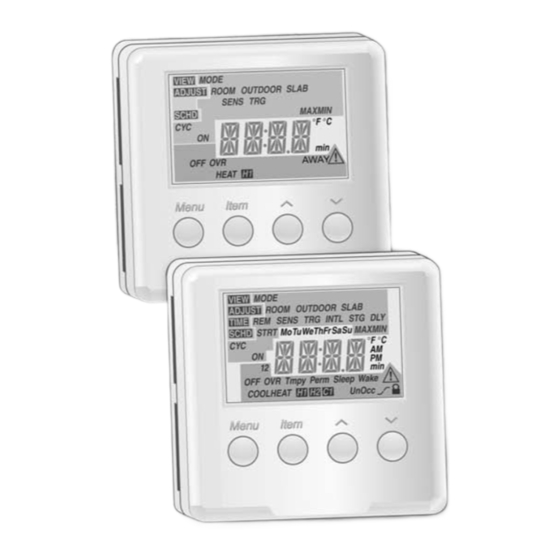
SetPoint 511s SetPoint 512 The SetPoint 511s and 512 Controllers are microprocessor-based controls that sense the air temperature in a specific area and increase the comfort level of that area as well as increase the energy efficiency of the heating or cooling system. -
Page 4: Section 2 - Installation
Check the contents of this package. If any contents listed below are missing or damaged, please contact your Uponor sales representative or distributor for assistance. • SetPoint 511s (part number A3041511) includes one programmable SetPoint Controller, one Floor Sensor (part number A3040079), an Installation and Operation Manual and a User Manual. -
Page 5: Rough-In Wiring
Installing the Front Cover Rough-in Wiring Note: 18 AWG or similar wire is recommended for all 24VAC wiring. Wiring Examples for the SetPoint 511s and SetPoint 512 1. Strip all wires to ⁄ " (6mm) to ensure proper connection to the control. - Page 6 Wiring to 24VAC Zone Valve 24VAC 24VAC Figure 7: Wiring the 511s Figure 6: Wiring the Zone Control Module (ZCM) 24VAC 24VAC 24VAC Figure 7: Wiring the 512 Section 2 — Installation...
-
Page 7: Display And Keypad Operation
An Auto Cycle setting is available for both the heating and cooling cycles. This setting determines the optimum number of cycles per hour to balance The SetPoint 511s and 512 Controllers feature four fields: Menu, Item, Number and Status. (See Figure 9.) temperature swings and equipment cycles. -
Page 8: Access Levels
In cases where a one-stage heating system cannot provide sufficient heat Sequence of Operation for the SetPoint 511s under all conditions, a second stage of heat is added to supplement the Air Sensor Only Operation first stage. -
Page 9: Sequence Of Operation For The Setpoint 512 (Two-Stage Heat)
Air Sensor Only Operation Sequence of Operation for the SetPoint 512 When operating with only an air sensor, the on times for the Heat 1 and (Heat and Cool) Controller Heat 2 relays are calculated to satisfy the requirements of the air sensor. Use the DIP switch located on the circuit board inside the thermostat to select the Heat and Cool mode of operation. -
Page 10: View Menu
Mode Section 3 Auto Navigating the Menus In the Auto mode, the controller automatically switches between heating and cooling the space. However, the heating operation has priority over the cooling operation. In this mode, the minimum slab or floor temperature is maintained even when the controller is cooling the air. - Page 11 ROOM HEAT CYC COOL (512 Only) This displays the desired temperature for heating This displays the number of cycles per hour (must set active air sensor to Heat or Auto). for cooling (only available in the Installer (See Figure 19.) access level).
- Page 12 ROOM HEAT WAKE ROOM COOL Sleep (512 Only) This displays the desired heating temperature This displays the desired cooling temperature when waking up. Set the active air sensor to when sleeping. Set the active air sensor to Heat or Auto. (See Figure 33.) Heat or Auto.
-
Page 13: Section 4 - Troubleshooting
Section 4 Troubleshooting Error Messages The controller was unable to read a piece of information stored in its memory and was required to load the factory settings. The controller will stop operation until all settings are checked. To clear this error, select the Installer access level Figure 45 and check all of the settings in the Adjust menu. -
Page 14: Section 5 - Technical Data
(See Figure 50.) Figure 50 Figure 51: SetPoint 511s SetPoint 511s Literature SetPoint 511s and 512 Controllers Installation and Operation Manual Control Microprocessor PI control; This is not a safety (limit) control. Packaged Weight 0.54 lb. -
Page 15: Setpoint 512
Notes Figure 52: SetPoint 512 SetPoint 512 Literature SetPoint 511s and 512 Controllers Installation and Operation Manual Control Microprocessor PI control; This is not a safety (limit) control. Packaged Weight 0.46 lb. (210 g), Enclosure J, white PVC plastic Dimensions ⁄... - Page 16 Notes...
Need help?
Do you have a question about the SETPOINT 511S and is the answer not in the manual?
Questions and answers