Table of Contents
Advertisement
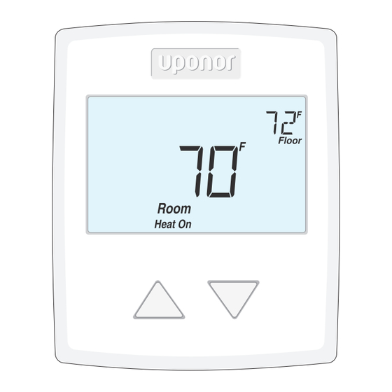
Single-stage SetPoint Controller
with Floor Sensor (A3041501)
Installation & Operation Manual
Introduction
The Uponor Single-stage SetPoint
Controller with Floor Sensor (A3041501)
accurately controls the room and/or floor
temperature for a hydronic heating zone
using Pulse Width Modulation (PWM)
technology. Simple up and down buttons
and
a display with large type make
this thermostat easy to read and
use. An optional Uponor Floor
Sensor (A3040079) is included to measure
floor temperature to protect the floor from
overheating and enhance comfort.
Energy-saving Features
• Auto Heating Cycle
Additional Features
• Radiant Floor Heating
• Pulse Width Modulation (PWM)
• Floor and Air Temperature Control
• Outdoor and Floor Temperature
Display
• Backlight
• Freeze Protection
• Includes Floor Sensor (A3040079)
Advertisement
Table of Contents

Related Manuals for Uponor A3041501


Summary of Contents for Uponor A3041501
- Page 1 Single-stage SetPoint Controller with Floor Sensor (A3041501) Installation & Operation Manual Introduction The Uponor Single-stage SetPoint Controller with Floor Sensor (A3041501) accurately controls the room and/or floor temperature for a hydronic heating zone Energy-saving Features using Pulse Width Modulation (PWM) •...
-
Page 2: Table Of Contents
Symbols Description ......11 Getting Started Congratulations on the purchase of your new Uponor thermostat. This manual will step through the complete installation, programming and sequence of operation for this control. At the back, there are tips for control and system troubleshooting. -
Page 3: Removing The Thermostat Base
- --- ------- ------- -- -- - - -- -- - -- -- -- - -- -- - Materials Required • 18 AWG LVT Solid Wire (Low-voltage Connections) ----- ------- ----- -- -- -- -- -- - -- -- -- - -- -- - Installation Location Choose the placement of the thermostats early in the construction process to enable proper wiring during rough-in. -
Page 4: Mounting The Thermostat
Mounting the Thermostat Thermostat Base Thermostat Front Wall If mounting directly to the wall: • Drill holes and install the wall anchors. • Feed the wiring through the large hole in the thermostat base. • Fasten the thermostat base to the wall using the wood screws to the wall anchors. •... -
Page 5: Floor Sensor Installation
Floor Sensor Installation ----- ------- ------ -- -- - -- - -- - -- -- -- - -- -- -- New Installations Thin-set or Thin-pour Applications If installing the floor covering over either a thin-set or thin-pour material of sufficient depth, the floor sensor can be placed directly into either the thin-set material or the thin-pour material and covered over. -
Page 6: Floor Sensor Wiring
------- -------- -- - -- -- -- - -- -- -- -- - -- -- -- Retrofit Installations Tile Floor Coverings If installing a Floor Sensor (A3040079) into an existing tile floor with sufficiently large grout lines, the sensor and wire can be installed in one of the grout lines between the tiles. Select a low-traffic area of the floor that is midway between the heating elements for the sensor location. -
Page 7: Floor Sensor Testing
Floor Sensor Testing A good-quality test meter capable of measuring up to 5,000 kΩ (1 kΩ = 1000Ω) is required to measure the sensor resistance. In addition, measure the actual temperature with either a good-quality digital thermometer, or if a thermometer is not available, place a second sensor alongside the one to be tested and compare the readings. - Page 8 Temperature vs. Resistance Table - Continued Temperature Resistance Temperature Resistance °F °C °F °C 5,828 1,538 5,210 1,403 4,665 1,281 4,184 1,172 3,760 1,073 3,383 3,050 2,754 2,490 2,255 2,045 1,857 1,689 www.uponorpro.com...
-
Page 9: Thermostat Wiring
Thermostat Wiring - ---- ----- ------- -------- -- - -- -- -- - -- -- -- - -- -- - Zone Valve Install field Zone jumper wire Valve R to Rh Floor Sensor (A3040079) No Power No Power Rh W1 S1 Rh W1 S1 24 V (ac) Transformer... -
Page 10: Testing The Thermostat Wiring
For DC power supplies, the voltage should measure between 10 to 30 V (dc). 3. If the voltage on the R and C wire terminations is continuous and the thermostat display is not on, the thermostat may have a fault. Contact your Uponor sales representative for assistance. -
Page 11: User Interface
User Interface Home Screen Symbols Description HEAT ON Heat is turned on. The floor is at or below the floor minimum temperature. MODE OFF The heating system is off. The floor has reached the floor WARNING SYMBOL maximum temperature. Indicates an error is present. Single-stage SetPoint Controller Installation &... -
Page 12: Sequence Of Operation
Sequence of Operation Heating Operation To change the heat temperature setting, push the button to select a preferred temperature setting. The Heat On symbol is shown on the display when the thermostat is heating. The heat can cycle on and off within +/- 1.5°F (1°C) of the temperature setting. The floor and air heating can be shut off by holding the button until Set Room is Off. -
Page 13: Programmable Settings
Programmable Settings Setting Display User settings. Press the buttons together for 3 seconds to enter and advance to the next setting. MODE Select heat or off. Range: HEAT, OFF Default: HEAT UNITS Select the temperature units. Range: °F or °C Default: °F LIGHT Select when the display backlight should operate. -
Page 14: Troubleshooting
The built-in air temperature sensor has an open circuit fault. Do not confuse this error with the auxiliary room sensor short circuit error. This error cannot be field repaired. Contact your wholesaler or Uponor sales Room representative for details on repair procedures. -
Page 15: Frequently Asked Questions
VA rating is recommended. Thermostat does Thermostat must be in Mode Heat in Mode Off not heat. order to provide heating. Technical Data Thermostat (A3041501) Control Microprocessor control; this is not a safety (limit) control. Packaged weight 0.6 lb. (290 g) Dimensions ⁄... - Page 16 Uponor, Inc. Uponor Ltd. 5925 148th Street West 2000 Argentia Rd., Plaza 1, Ste. 200 Apple Valley, MN 55124 USA Mississauga, ON L5N 1W1 CANADA Tel: 800.321.4739 Tel: 888.994.7726 Fax: 952.891.2008 Fax: 800.638.9517 www.uponorpro.com...
Need help?
Do you have a question about the A3041501 and is the answer not in the manual?
Questions and answers