Table of Contents
Advertisement
Quick Links
Advertisement
Table of Contents

Subscribe to Our Youtube Channel
Related Manuals for Jetter JC-120MC


Summary of Contents for Jetter JC-120MC
- Page 1 User Manual JC-120MC - Controller 60880901 We automate your success.
- Page 2 In the case of modifications, further developments or enhancements to products shipped in the past, a revised document will be supplied only if required by law, or deemed appropriate by Jetter AG. Jetter AG shall not be liable for errors in form or content, or for missing updates, as well as for damages or disadvantages resulting from such failure.
- Page 3 +49 7141 2550-484 E-mail - Sales: sales@jetter.de E-mail - Technical Hotline: hotline@jetter.de Assignment to product This User Manual is an integral part of JC-120MC: Type: Serial #: Year of manufacture: Order #: To be entered by the customer: Inventory #:...
- Page 4 Significance of this This document is an integral part of the JC-120MC: User Manual Keep this document in a way that it is always at hand until the JC-120MC will be disposed of. Pass this document on if the JC-120MC is sold or loaned/leased out.
-
Page 5: Table Of Contents
Instructions on EMI ........................16 Product description and design Product description of the JC-120MC ..................20 Parts and interfaces of the controller JC-120MC ................. 21 Order reference/options ....................... 22 List of documentation ........................23 Accessories for the JX3 system ....................25 Physical dimensions ........................ - Page 6 IP address in the GNN operating mode ..................89 Using names for IP addresses ....................91 Engineering of JX3 station equipped with a JC-120MC ............93 4.7.1 Limitations to be taken into account when engineering a JX3 station ........ 94 Limitations of the maximum number of modules.................
- Page 7 Register and I/O numbers with a JC-120MC ................. 211 Registers and module registers ....................212 Register and I/O numbers of JX3 modules connected to a JC-120MC ........214 Register numbers of JX2 slave modules connected to the JX2 system bus ......215 Registers and I/O numbers of JX2-I/O modules on the JX2 system bus ........
- Page 8 Hardware Manager ........................254 Hardware Manager ........................255 10.3.4 Error handling at the Jetter Ethernet system bus ............... 256 Acyclic data interchange - Error logging ................... 257 Error message during CRC computing ..................258 Error message on part of a subscription ................... 259 Controller evaluates errors reported by a remote network node..........
- Page 9 JC-120MC Contents Cursor position ........................... 326 Clearing the screen ........................328 10.9.5 Displaying numerical values....................330 STX instruction for displaying numerical values ................ 331 Device numbers ......................... 332 Cursor position ........................... 334 Setting the length of the display field ..................336 Setting the sign option .......................
- Page 10 Sending values .......................... 481 Receiving characters ......................... 482 Receiving values ........................483 10.17 User-programmable IP interface .................... 484 10.17.1 Programming ........................... 486 Initializing the user-programmable IP interface ................. 487 Establishing a connection ......................488 Sending data ..........................492 Jetter AG...
- Page 11 JC-120MC Contents Receiving data ........................... 494 Terminating a connection ......................497 10.17.2 Registers ........................... 498 Register numbers ........................499 Register description ........................500 10.18 CANopen® STX API ......................... 503 STX function: CanOpenInit() ...................... 507 STX function: CanOpenSetCommand() ..................509 STX function: CanOpenUploadSDO() ..................511 STX function: CanOpenDownloadSDO() ...................
- Page 12 Motion Control Quick reference - JC-120(MC) Appendix Technical specifications ......................622 JC-120MC: Technical data ......................623 Physical dimensions ........................625 Operating parameters - Environment and mechanics .............. 626 Operating parameters: Enclosure ..................... 627 DC power supply inputs and outputs ..................628 Shielded data and I/O lines .......................
-
Page 13: Safety Instructions
JC-120MC Safety instructions Safety instructions Introduction This chapter informs the user of basic safety instructions. It also warns the user of residual dangers, if there are any. Furthermore, it contains information on EMC. Contents Topic Page Basic safety instructions ................14 Instructions on EMI .................. -
Page 14: Basic Safety Instructions
The controller JC-120MC is used to control machinery, such as conveyors, production machines, and handling machines. Operate the controller JC-120MC only within the limits and conditions set forth in the technical specifications. The operating voltage of the controller JC-120MC is classified as SELV (Safety Extra Low Voltage). Therefore, the JC-120MC controller is not subject to the EU Low Voltage Directive. - Page 15 Jetter AG. The installation of such parts may impair the safety and the proper functioning of the device. Any liability on the part of Jetter AG for any damages resulting from the use of non-original parts and equipment is excluded. Transport The JC-120MC contains electrostatically sensitive components which can be damaged if not handled properly.
-
Page 16: Instructions On Emi
Measures Measures for increasing EMI in electric plants: Attach the JC-120MC to a DIN rail to EN 60715 having got the dimensions 35 x 7.5 mm. The DIN rail must be electrically conducting and grounded by either of the two ways: •... - Page 17 Safety instructions Downloading Application You can download Application Note 016 EMC-Compatible Installation of Note 016 Electric Cabinets from the Jetter AG homepage http://www.jetter.de. In order to download Application Note 016, browse the following path: Downloads - Application Notes. Jetter AG...
-
Page 19: Product Description And Design
Contents Topic Page Product description of the JC-120MC ............20 Parts and interfaces of the controller JC-120MC ......... 21 Order reference/options ................22 List of documentation..................23 Accessories for the JX3 system ..............25 Physical dimensions ..................26... -
Page 20: Product Description Of The Jc-120Mc
Product description of the JC-120MC The controller JC-120MC The JC-120MC is a high-end compact controller covering all areas of industrial automation thanks to its high performance in combination with motion control. Besides traditional controller functions, JC-120MC offers a motion control feature which allows for programming axis groups and complex path controls. -
Page 21: Parts And Interfaces Of The Controller Jc-120Mc
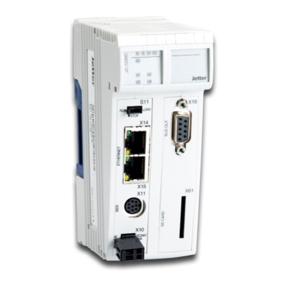
JC-120MC Product description and design Parts and interfaces of the controller JC-120MC Parts and interfaces The controller JC-120MC features the following parts and interfaces: Number Part Description Upper latch Lets you remove the module enclosure from the backplane module JX2 system bus interface and CANopen®... -
Page 22: Order Reference/Options
Specify your desired options in the order. The controller cannot be equipped options with additional features afterwards. Integrated Web server The integrated Web server and e-mail feature of the JC-120MC support the and e-mail feature following functions by default: ... -
Page 23: List Of Documentation
Product description and design List of documentation Introduction Various documents and software tools support you in engineering, installing and programming the JC-120MC controller. You can download these documents and software tools from the Jetter AG homepage http://www.jetter.de. Engineering The following documents and files support you in engineering the controller: Industrial automation catalog ... - Page 24 Excel file for designing the JX3 system bus JX3-SysBus_Configurator_xxx_e.xls (xxx: Version) Installation The following documents support you at installing the controller: Installation manual It is included in the boxed controller JC-120MC and contains information on: Installing the controller on a DIN rail Terminal assignment ...
-
Page 25: Accessories For The Jx3 System
JC-120MC Product description and design Accessories for the JX3 system Labelling strips Ten labelling strips are included in the scope of delivery of the JC-120MC. Order reference DIV_DEK_5/5_MC-10_NEUT_WS Item no. 60870411 Packaging unit 100 pcs. Keying pins Order reference DIV_BL_SL_3.5_KO_OR Item no. -
Page 26: Physical Dimensions
Minimum clearance, below: 25 mm Module width The width of the JC-120MC is 56 mm. When the JC-120MC is attached to a JX3 station, its width increases by 50 mm. Mounting orientation The orientation of the JC-120MC is vertical. -
Page 27: Identifying
The programming software JetSym 5.2.1 or higher is installed on the PC. Information for hotline If you wish to contact the hotline of Jetter AG in case of a problem, please requests have the following information on the JC-120MC ready: ... -
Page 28: Identification By Means Of The Nameplate
The nameplate is attached to the housing of the JC-120MC and contains details, such as hardware revision number and serial number. If you wish to contact the hotline of Jetter AG in case of a problem, please have this information ready. -
Page 29: Nameplate
JC-120MC Identifying Nameplate Nameplate The nameplate of a JC-120MC controller contains the following information: S. / N . : 20080130060039 Part No.:10000704 JC-120x-x Rev.: 02.00.00 Number Description Serial number Controller name Hardware revision Item number Jetter AG... -
Page 30: Electronic Data Sheet Eds
Introduction Each JC-120MC features an Electronic Data Sheet (EDS). Numerous production-relevant data are permanently stored in the EDS. The EDS data can be read out via files in the file system of the JC-120MC or via special registers. Contents Topic Page EDS file ...................... -
Page 31: Eds File
JC-120MC Identifying EDS file Introduction EDS data can be retrieved from the file eds.ini. Properties You can access this file through the file system of the controller. For an FTP connection, the user needs administrator rights (user admin) or system rights (user system). - Page 32 3 Identifying Example This is an example of an EDS file belonging to a JetControl 120MC: ;Jetter AG Electronic Data Sheet [IDENTIFICATION] Version = 2 Code = 879 Name = PcbRev = 00 PcbOpt = 00 OSVersionMin = 0.0.0.0 BLVersionMin = 0.0.0.0...
- Page 33 Function PcbRev Hardware revision PcbOpt Hardware option OSVersionMin 0.0.0.0 The JC-120MC is available as of this OS version BLVersionMin 0.0.0.0 The JC-120MC is available as of this bootloader version Section [PRODUCTION] The serial number and production date can be seen from section [PRODUCTION].
- Page 34 3 Identifying Name Example Function A real-time clock is available Example: JX3 modules Examples of EDS files for JX3 modules: Please refer to the manual of the corresponding module. Related topics EDS registers (see page 35) Jetter AG...
-
Page 35: Eds Registers
JC-120MC Identifying EDS registers Introduction EDS registers let you retrieve entries in the Electronic Data Sheet (EDS). Register numbers The basic register number is dependent on the controller. The register number is calculated by adding the number of the module register (MR) to the number of the basic register. - Page 36 LED of the SD card slot MR 816 UserLEDs User-defined LEDs MR 817 Real-time clock EDS file of JX3 modules The assignment of module registers 6xx and 7xx corresponds to the assignment with JX3 module. Related topics EDS file (see page 31) Jetter AG...
-
Page 37: Version Registers
The operating system provides several registers which can be used to read out the revision number of the hardware or the version of the operating system and its components. If you wish to contact the hotline of Jetter AG in case of a problem, please have this specifications ready. -
Page 38: Hardware Revisions
3 Identifying Hardware revisions Introduction The JC-120MC features special registers, the content of which lets you identify the hardware. Register overview The following registers let you read out the hardware revisions: Register Description 108020 Hardware revision of the backplane module... -
Page 39: Software Versions
JC-120MC Identifying Software versions Introduction The JC-120MC features software with unique version numbers which can be read out from special registers. Format of software The software version numbers of the JC-120MC are four-figure values. version numbers Element Description Major or main version number... - Page 40 3 Identifying Related topics Hardware revisions (see page 38) Jetter AG...
-
Page 41: Mechanical And Electrical Installation
JC-120MC Mechanical and electrical installation Mechanical and electrical installation Purpose of this chapter This chapter deals with mechanical and electrical installation of the JC-120MC regarding the following aspects: Wiring the JC-120MC Description of the indicators Description of control elements ... -
Page 42: Interfaces
4 Mechanical and electrical installation 4.1 Interfaces Terminal X10 The function of terminal X10 is as follows: Power supply for the controller JC-120MC Power supply for connected JX3 peripheral modules Port X11 The function of port X11 is a serial interface and lets you connect the following devices: ... -
Page 43: Power Supply Terminal X10
-15 % ... +20 % Input current without HMI 1.0 A max. Power consumption 24 W max. Connector for power A 2-pin connector is included in the scope of delivery of the JC-120MC. supply terminal X10 Designation BU_02_E_BLZF_GE_RM3.5 Item no. 60870409... -
Page 44: Serial Interface Port X11
Serial interface port X11 Devices to connect with Port X11 lets you connect the following devices: this port A PC An HMI by Jetter AG Any device Pin assignment of port X11 Signal Description RS-422; receive data inverted Reference potential RS-422;... - Page 45 JC-120MC Mechanical and electrical installation Block diagram +3V3 33 kΩ X11.3 [RDB] X11.1 [RDA] 33 kΩ +3V3 33 kΩ X11.5 [SDB] X11.7 [SDA] 33 kΩ Number Part Function in the case Function in the case of RS-422 of RS-485 Receiver...
- Page 46 JetControl to LCD 52/54 with 15-pin Sub-D, length 0.25 m 60864257 Cable assy # 197 5M JetControl to JetView 200/300 with 9-pin Sub-D, length 5 m 60871930 Cable assy # 197 12M JetControl to JetView 200/300 with 9-pin Sub-D, length 12 m Jetter AG...
-
Page 47: Ethernet Ports - Female Connectors X14, X15
Devices to connect with Ports X14 and X15 let you connect the following devices: these ports A PC An HMI by Jetter AG A JX3-BN-ETH, a JX3-COM-xxxx, or a JetMove-200-ETH Any device Pin assignment Ports X14 and X15 are internally connected via Ethernet switch. -
Page 48: Can Bus Interface - Female Connector X19
4.2 CAN bus interface - Female connector X19 Introduction This chapter describes the JX2 system bus interface and a CANopen® interface (CANopen® STX API) on the JC-120MC. At connector X19 two CAN buses are brought out. Breakout cable To use both CAN buses, connect a Y-cable to connector X19. -
Page 49: Female Connector X19 - Pin Assignment
JC-120MC Mechanical and electrical installation Female connector X19 - Pin assignment Pin assignment of female connector X19 Signal Description CMODE0 Commissioning CAN-L Data signal for CAN bus 1 Reference potential CMODE1 Commissioning Unused CAN-L_2 Data signal for CAN bus 2... - Page 50 Cable assy # 530 4.0 m 10309008 Cable assy # 530 5.0 m Related topics Y-cable - Specification (see page 51) JX2 system bus cable - Specification (see page 53) Line length (in mm) and baud rate (see page 55) Jetter AG...
-
Page 51: Specification Of The Y Cable
JC-120MC Mechanical and electrical installation Specification of the Y cable Parts and connection diagram Number Element Description Male sub-D connector, 9-pin For connection to BUS OUT Female sub-D connector, For connection to BUS IN (CAN 1) 9-pin Female sub-D connector,... - Page 52 Data signal CAN 1 Sub-D connector (CAN 2) Pinout of the 9-pin female Sub-D connector (CAN 2) on the Y-cable: Signal name Description CMODE0 Commissioning CAN-L_2 Data signal CAN 2 Reference potential CMODE1 Commissioning CAN-H_2 Data signal CAN 2 Jetter AG...
-
Page 53: Jx2 System Bus Cable Specification
JC-120MC Mechanical and electrical installation JX2 system bus cable specification JX2 system bus cable Parameter Description specification Core cross-sectional area 1,000 kBaud: 0.25 … 0.34 mm 500 kBaud: 0.34 … 0.50 mm 250 kBaud: 0.34 … 0.60 mm 125 kBaud: 0.50 … 0.60 mm Cable capacitance 60 pF/m max. - Page 54 Short-circuited with pin 3 CAN-H Data signal Female Sub-D connector Pinout of the 9-pin female Sub-D connector to the JX2 system bus cable: Signal name Description CMODE0 Commissioning CAN-L Data signal Reference potential CMODE1 Commissioning CAN-H Data signal Jetter AG...
-
Page 55: Line Length And Baud Rate Of The Jx2 System Bus
JC-120MC Mechanical and electrical installation Line length and baud rate of the JX2 system bus Cable lengths The maximum cable length depends on the baud rate used and the number of expansion modules connected to the bus. Baud rate Cable length... -
Page 56: Leds Indicating Various States
4 Mechanical and electrical installation 4.3 LEDs indicating various states LEDs of the JC-120MC The JC-120MC features the following LEDs: 5 LEDs for indicating conditions and errors of the controller 4 LEDs for indicating user-defined events 4 LEDs for indicating the conditions of the Ethernet ports... -
Page 57: Leds Of The Controller
JC-120MC Mechanical and electrical installation LEDs of the controller LEDs of the controller The controller JC-120MC indicates conditions and errors via its LEDs. There are three groups of LEDs: Status messages of the operating system Application-specific LEDs ... - Page 58 Reset or second part of startup delay is carried out, or fatal error has occurred. File autocopy.ini on SD card is being executed. Boot loader is not running Boot loader: Automatic IP configuration Reset or fatal error Boot loader is being executed Jetter AG...
-
Page 59: Leds Of The Controller During Boot Process
JC-120MC Mechanical and electrical installation LEDs of the controller during boot process Normal boot process If the following requirements are met, the controller goes through its normal boot process: Mode selector S11 is in RUN position. There is a valid OS. - Page 60 The second half of the start delay is in progress State The OS initializes the modules on the JX3 and JX2 system bus, as well as software features (Web, Modbus/TCP, etc.); then it loads the application program. State Normal operating condition Jetter AG...
-
Page 61: Led Indications On The Controller After An Ip Address Conflict Has Been Detected
JC-120MC Mechanical and electrical installation LED indications on the controller after an IP address conflict has been detected IP conflict detected During booting or after the IP address has been modified through NetConsistency, the controller checks its own IP address. If the controller... -
Page 62: Status Leds - Ethernet Interface
The status LEDs of the Ethernet interface are located in the immediate vicinity interface of the RJ45 ports. Color Description X14-1 Green LINK: Network connection has been established X14-2 Amber ACT: Data transmission X15-3 Green LINK: Network connection has been established X15-4 Amber ACT: Data transmission Jetter AG... -
Page 63: Controls And Sd Memory Card
The JC-120MC is equipped with the following controls: JC-120MC Mode selector S11 with the following positions: RUN, STOP, and LOAD SD card The JC-120MC is equipped with a slot for SD memory cards. Contents Topic Page Function description of mode selector S11........... 64 SD card slot X61 ................... -
Page 64: Function Description Of Mode Selector S11
LOAD The controller executes the file autocopy.ini which is located on the SD card. Functions of the mode The JC-120MC checks the position of selector S11 in the following way: selector Step Description Power supply of the controller is at terminal X10. - Page 65 JC-120MC Mechanical and electrical installation Step Description If ..then ..the position of mode selector ... this has no effect on the S11 is changed once the controller functioning of the controller. has been turned on, ...
-
Page 66: Sd Card Slot X61
Insert the SD card into the SD slot as illustrated below. The way of inserting the SD card correctly is the same as in common digital cameras. If the SD card has been inserted correctly, the status LED SD lights up for 300 ms. Jetter AG... - Page 67 JC-120MC Mechanical and electrical installation Removing the SD card Make sure the SD card is not accessed, while you are removing it. First, close all files which are stored to the SD card. Remove the SD card the same way as you do it with digital cameras.
-
Page 68: Installing, Replacing And Removing The Module
This chapter covers mounting, replacing and removing of controllers belonging to the JetControl 120 series. Contents Topic Page Installing the JC-120MC on a DIN rail ............69 Replacing the controller JC-120MC .............. 70 Removing the JC-120MC from the DIN rail ..........72 Jetter AG... -
Page 69: Installing The Jc-120Mc On A Din Rail
Installation of the controller on the DIN rail is now completed. Related topics Replacing the controller JC-120MC (see page 70) Removing the controller JC-120MC from the DIN rail (see page 72) Jetter AG... -
Page 70: Replacing The Controller Jc-120Mc
Gateway DNS server Removing the controller To remove the JC-120MC from the backplane module, proceed as follows: Step Action Remove power from the JX3 station. Press the upper and lower latches located on the right half of the JC-120MC. - Page 71 JC-120MC Mechanical and electrical installation Installing the controller To install the JC-120MC on the backplane module, proceed as follows: Step Action Slide the controller onto the backplane module until the latches snap into place. Installation of the controller to the backplane module is now completed.
-
Page 72: Removing The Jc-120Mc From The Din Rail
4 Mechanical and electrical installation Removing the JC-120MC from the DIN rail Removing To remove the JC-120MC from a rail to DIN EN 50022 proceed as follows: Step Action Remove power from the JX3 station. Slide the controller to the left. By doing so, the backplane module is disconnected from the JX3 peripheral modules. -
Page 73: Ip Configuration
Basic port number for communication via JetIP Name for AutoCopy command file Required skills of the To carry out IP configuration of the JC-120MC knowledge of IP networks is network configurator required, such as IP addressing (IP address, port number, subnet masks etc.) ... -
Page 74: Factory Settings
4 Mechanical and electrical installation Factory settings Introduction Before the JC-120MC is shipped, various parameters are set to a certain value. The parameters can be changed by the user. Factory settings Parameter Value IP address of the controller 192.168.1.1 Subnet mask 255.255.255.0... -
Page 75: The Configuration Memory
JC-120MC Mechanical and electrical installation The configuration memory Introduction The controller reads the parameters for initializing the IP interface out of the configuration memory during the boot process. The user can access the data stored in the configuration memory in the following ways: A file located in the system directory of the file system lets you read out ... -
Page 76: The Configuration File
The configuration file config.ini is used to access the configuration memory of the JC-120MC. Properties You can access this file through the file system of the JC-120MC. For an FTP connection, the user must have administrator or system rights. ... - Page 77 DefGateWay In the given example 192.168.50.11 Description IP address of the gateway to other subnets; The JC-120MC must be able to reach the subnet (Address/SubnetMask), otherwise it will set this parameter to 0.0.0.0. Allowed values >= 0.0.0.0 and ...
- Page 78 4 Mechanical and electrical installation Section [HOSTNAME] In section [HOSTNAME] the name of the JC-120MC is specified. If desired, the JC-120MC automatically generates an individual name. The JC-120MC presently does not use the host name. SuffixType In the given example...
- Page 79 Create on your PC a configuration file named config.ini using a text editor and make the corresponding entries. Open an FTP connection between the PC and the JC-120MC. Log in as user with administrator or system rights. Default login information: User: admin, Password: admin User: system;...
-
Page 80: Configuration Registers
(MR) to the number of the basic register. Device Data range Basic register Register numbers number JC-120MC Configuration 101100 101100 ... 101165 memory Parameters 101200 101200 ... 101265... -
Page 81: Changing The Ip Address Of The Controller
Mechanical and electrical installation Changing the IP address of the controller Introduction To be able to communicate with the controller JC-120MC via Ethernet, you must set an unambiguous IP address on the controller. Replacing the controller The IP address is stored to the backplane module. When you install another... -
Page 82: Setting The Default Ip Address 192.168.10.15
Default IP address The controller JC-120MC has got default IP address 192.168.10.15. You may change the IP address of the JC-120MC to its default IP address at any time. DIP switch settings To set the module to its default IP address 192.168.10.15, move the... -
Page 83: Setting The Ip Address Via Configuration File
JC-120MC Mechanical and electrical installation Setting the IP address via configuration file Setting the IP address You can set the IP address of the controller JC-120MC in the config.ini file. [IP] Address = aaa.bbb.ccc.ddd Element Description Address Enter the IP-address into this line. -
Page 84: Setting The Ip Address Via Configuration File And Dip Switch
IP address in theconfig.ini file, and the lower byte using the DIP switch sliders. Configuration file - Set the upper three bytes of the IP address of the JC-120MC in the configuration file config.ini file. Setting the IP address... - Page 85 Mechanical and electrical installation Transferring the Step Action configuration file Establish an FTP connection to the JC-120MC. Log in as user with administrator or system rights. Default login information: User: admin; Password: admin User: system; Password: system Open the folder System.
-
Page 86: Setting The Ip Address Via Registers To Be Non-Volatile
For this, write value 2002149714 (0x77566152) to register 101299. Wait for the controller to write value 0 into MR 101299. The save process is now completed. Boot the controller. Result: The settings are completed. Communication is possible again. Jetter AG... - Page 87 JC-120MC Mechanical and electrical installation Important note: The EEPROM data on the backplane module allow for 100,000 write cycles. We urgently recommend the following workflow: First read out the value, then compare it. Only if the value has changed, start writing.
-
Page 88: Setting The Ip Address During Runtime
This is important because there is no check if you set the parameters during runtime of the controller. Register overview Register Description 104531 IP address of the JC-120MC 104532 Subnet mask 104533 IP address of default gateway Setting IP addresses and... -
Page 89: Ip Address In The Gnn Operating Mode
Third byte of IP address Fourth byte of IP address DIP switch settings The following DIP switch settings cause the JC-120MC to read out the IP address from the file config.ini and the GNN out of the lower eight positions of the DIP switches: Valid values for the GNN: 1 ... - Page 90 4 Mechanical and electrical installation DIP switch Invalid Invalid Jetter AG...
-
Page 91: Using Names For Ip Addresses
Names are resolved to IP addresses in the following way: Step Description During the boot process the JC-120MC reads the IP address of the DNS server out of the configuration memory. During the boot process the JC-120MC reads the file /etc/hosts. The JC-120MC creates a translation table with the names and IP addresses found in this file. - Page 92 192.168.1.2 JC350 Domain Name System If a name cannot be found in the file /etc/hosts, the JC-120MC tries to obtain (DNS) the corresponding IP address from a DNS server. During boot-up, the JC-120MC reads the IP address of the DNS server out of the configuration memory.
-
Page 93: Engineering Of Jx3 Station Equipped With A Jc-120Mc
This chapter describes how to engineer a JX3 station equipped with a JC-120MC. JX3 station A JX3 station consists of a JX3-BN-xxx bus node or a JC-120MC controller and JX3 peripheral modules connected to it. Number of connectable The possible number of JX3 modules depends on the following parameters: JX3 modules ... -
Page 94: Limitations To Be Taken Into Account When Engineering A Jx3 Station
The following fields marked red convey the following meaning: Total number of modules The maximum number of 16 JX3 modules per JX3 station has been exceeded. IN size of JX3 station The aggregated input factor has been exceeded. Jetter AG... - Page 95 The following fields marked red convey the following meaning: Number of modules The maximum number of 8 JX3 modules connected to JC-120MC, JX3-BN-xxx, or JX3-PS1 has been exceeded. Integrate the JX3-PS1 in your JX3 station. ...
-
Page 96: Topic Page
4 Mechanical and electrical installation Contents Topic Page Limitations of the maximum number of modules .......... 97 Limitations of the modules' data exchange rates .......... 98 Limitation depending on the power consumption of the modules....101 Jetter AG... -
Page 97: Limitations Of The Maximum Number Of Modules
In addition, you can connect up to eight JX3 peripheral modules to a JX3-PS1 power supply module. Fully equipped The following illustration shows a JX3 station with a JC-120MC controller and JX3 station 16 JX3 peripheral modules. Downstream the eighth JX3 peripheral module a JX3-PS1 power supply module has been inserted. -
Page 98: Limitations Of The Modules' Data Exchange Rates
JX3-BN-CAN using the JX2 system bus protocol, or via JX3-BN-ETH using the Ethernet system bus protocol. JX3 modules of a JX3 station exchange data either with a JC-120MC controller, or with bus node modules JX3-BN-CAN and JX3-BN-ETH. The maximum number of input and output data and of JX3 peripheral modules in a JX3 system is limited. - Page 99 Example: 2 JX3-DI16 and 8 JX3-AI4 modules are connected to a controller JC-120MC. 2 JX3-DI16 with input factor 4 makes 8; 8 JX3-AI4 with input factor 10 makes 80 => aggregated factor is 88. Calculate the aggregated output factor by adding the output factor per module.
- Page 100 0,5A DC24V Number Part Description JC-120MC Controller JX3-AO4 Modules 1 to 5 supplied by JC-120MC (1) JX3-PS1 Power supply module JX3-AO4 Modules 6 to 11 supplied by JX3-PS1 (3) JX3-PS1 Power supply module JX3-THI2-RTD Modules 12 to 16 supplied by JX3-PS1 (5)
-
Page 101: Limitation Depending On The Power Consumption Of The Modules
Introduction JX3 modules of a JX3 station are supplied with logic voltage either by a JC-120MC controller, or a JX3-BN-xxx bus node, or a JX3-PS1 power supply module. Each of these modules is able to supply up to 8 downstream JX3 modules with logic voltage. - Page 102 ... Example You want to connect 11 JX3-AO4 and 5 JX3-THI2-RTD to a controller JC-120MC. Check by taking the following steps how the JX3 station must be engineered to keep power consumption from exceeding the permitted value. Step Action...
- Page 103 24 V: For JC-120MC: For JX3-PS1: This module lets you directly connect up to 5 JX3-AO4 to a JC-120MC. Then, insert a JX3-PS1. Then, you can connect the remaining 6 JX3-AO4 to this JX3-PS1. Determine the current consumption of the JX3 module JX3-THI2-RTD given in the technical data: ...
- Page 104 0,5A DC24V Number Part Description JC-120MC Controller JX3-AO4 Modules 1 to 5 supplied by JC-120MC (1) JX3-PS1 Power supply module JX3-AO4 Modules 6 to 11 supplied by JX3-PS1 (3) JX3-PS1 Power supply module JX3-THI2-RTD Modules 12 to 16 supplied by JX3-PS1 (5)
- Page 105 0,5A DC24V Number Part Description JC-120MC Controller JX3-AO4 Modules 1 to 5 supplied by JC-120MC (1) JX3-PS1 Power supply module JX3-AO4 Modules 6 to 11 supplied by JX3-PS1 (3) JX3-THI2-RTD Modules 12 and 13 supplied by a JX3-PS1 (3) JX3-PS1...
-
Page 106: Configuring The Jx2 System Bus
This chapter is on configuring the JX2 system bus. Number of connectable The following table shows the maximum number of modules which you can modules connect in parallel to the JX2 system bus of the JC-120MC. Controller JX2-I/O modules JX-SIO... -
Page 107: Wiring The Jx2 System Bus
JC-120MC Mechanical and electrical installation 4.8.1 Wiring the JX2 system bus Introduction This chapter gives a description of the physical structure of the JX2 system bus. Contents Topic Page Line length and baud rate of the JX2 system bus ........108 JX2 system bus topology ................ -
Page 108: Line Length And Baud Rate Of The Jx2 System Bus
Each connected IP67-I/O module reduces the maximum line length by 1.0 m Baud rate The baud rate setting depends on the number of modules connected to the JX2 system bus: JX2-I/O modules JX-SIO 1,000 kBaud kBaud kBaud kBaud JX2 slave modules CANopen® modules JetMove Jetter AG... -
Page 109: Jx2 System Bus Topology
Mechanical and electrical installation JX2 system bus topology Remote arrangement The JX2 system bus lets you connect one or several remote modules to a JC-120MC. The overall distance from the controller may add up to 200 meters. Jetter LOAD STOP... -
Page 110: Power Supply Of Jx2-I/O Modules
JX2-PS1 modules. Number Part Description JX2 system bus cable connecting to the controller JX2-PS1 Power supply module JX2-I/O A maximum of five JX2-I/O modules equipped with various interfaces JX2 system bus cable leading to additional modules Jetter AG... - Page 111 JC-120MC Mechanical and electrical installation Power supply of One input/output module JX2-IO16 supplies up to three JX2-I/O modules. modules using JX2-IO16 Number Part Description JX2 system bus cable connecting to the controller JX2-IO16 Input/output module JX2-I/O A maximum of three JX2-I/O modules equipped...
-
Page 112: Power Supply Of Jx2 Slave Modules
JX2 system bus cable connecting to the controller JX2-PS1 Power supply module JX2-I/O A maximum of five JX2-I/O modules equipped with various interfaces JX2 slave JX2 slave modules with power supply of their own (other than JetMove) JX2 system bus cable leading to additional modules Jetter AG... -
Page 113: Connecting Displays And Hmis
JC-120MC Mechanical and electrical installation 4.9 Connecting displays and HMIs Introduction This chapter covers the connection of alphanumeric displays and HMIs to the JC-120MC. Contents Topic Page Overview of displays and HMIs ..............114 Connecting a display or HMI ............... 115 Connecting several displays or HMIs: Multi-display mode ...... -
Page 114: Overview Of Displays And Hmis
4 Mechanical and electrical installation Overview of displays and HMIs List of displays and HMIs The following table lists the alphanumeric displays HMIs by Jetter AG which you can connect to the JC-120MC. Order Display Keys Interface cable reference LCD 16 ... -
Page 115: Connecting A Display Or Hmi
Connecting a display or HMI Connecting a display or There are prefabricated cables for connecting a display or HMI made by Jetter AG to a JC-120MC. We recommend to use the prefabricated cables listed in the above table. Interface Connect the display or HMI via serial interface to jack X11. To do so, apply connections to interface standard RS-422. -
Page 116: Connecting Several Displays Or Hmis: Multi-Display Mode
Connecting several displays or HMIs: Multi-display mode Introduction Multi-display mode allows a JC-120MC to be operated with up to four alphanumeric displays and HMIs connected to one of the serial interfaces. When doing so, the various HMIs display the same or different texts and/or variable contents. -
Page 117: Multi-Display Mode - Wiring
JC-120MC Mechanical and electrical installation Multi-display mode - Wiring Wiring There are no prefabricated cables for connecting several displays or HMIs to a controller. Assemble the cables for multi-display mode according to the following block diagram: Signal Signal 24 V DC... - Page 118 4 Mechanical and electrical installation Number Part Description Jack X11 Serial interface of the JC-120MC Shielding Use shielded cables both ends of which are connected to the metallized housing of the connector. Power supply If several displays and HMIs are used, each of them must be individually connected to the power supply.
-
Page 119: Interface Cable Jc-Dk-Xm
JC-120MC Mechanical and electrical installation Interface cable JC-DK-Xm Introduction The interface cable JC-DK-Xm lets you connect displays or HMIs to the JC-120MC. Male connector For information on connector specification refer to the list below: specification Type 8-pin male MiniDIN connector... - Page 120 JetControl to HMI with 15-pin Sub-D, length 7 m 60872142 Cable assy # 192 10M JetControl to HMI with 15-pin Sub-D, length 10 m 60872884 Cable assy # 192 15M JetControl to HMI with 15-pin Sub-D, length 15 m Jetter AG...
-
Page 121: Interface Cable Kay_0386-Xxxx
JC-120MC Mechanical and electrical installation Interface cable KAY_0386-xxxx Introduction The interface cable KAY_0386-xxxx lets you connect HMIs of the type LCD 60 to the JC-120MC. Male connector For information on connector specification refer to the list below: specification Type 8-pin male MiniDIN connector... - Page 122 The interface cable KAY_0386-xxxx is prefabricated and available in the following lengths: Item no. Item Description 60864359 KAY_0386-0250 JetControl to LCD 60 with 15-pin Sub-D, length 2.5 m 60864360 KAY_0386-0500 JetControl to LCD 60 with 15-pin Sub-D, length 5 m Jetter AG...
-
Page 123: Interface Cable Kay_0533-0025
Mechanical and electrical installation Interface cable KAY_0533-0025 Introduction The interface cable KAY_0533-0025 lets you connect HMIs of the type LCD 52, LCD 54 and LCD 54Z to the JC-120MC. Male connector For information on connector specification refer to the list below: specification... - Page 124 A metallized housing is required Signal +24 V DC Available lengths: The interface cable KAY_0533-0025 is prefabricated and available in the following lengths: Item no. Item Order reference 60864897 KAY_0533-0025 JetControl to LCD 52/54 with 15-pin Sub-D, length 0.25 m Jetter AG...
-
Page 125: Initial Commissioning
Creating and executing a program to set and reset output 9 of the peripheral module JX3-DIO16 Prerequisites For initial commissioning the JC-120MC, the following prerequisites must be fulfilled: The controller is connected to a PC via Ethernet. ... -
Page 126: Preparatory Work For Initial Commissioning
5 Initial commissioning Preparatory work for initial commissioning Ethernet connection with The JC-120MC in delivered condition has got IP address 192.168.1.1. the controller Configure the Ethernet interface of your PC so that it communicates with the controller via this IP address. -
Page 127: Initial Commissioning Of A Jc-120Mc
In JetSym, start the Hardware Manager either by clicking on the tab Hardware with the mouse (keyboard shortcut [Alt] + [5]). Open the window for controller configuration by double-clicking the folder CPU in the Hardware Manager. Select the controller type JC-120MC. Enter the following information: ... - Page 128 Autorun Loop Inc(Count); Delay(T#2s); End_Loop; End_Task; Setup pane The JetSym setup window displays the content of the variable: Number Description Function Present content of the The content of the variable is incremented by variable one every 2 seconds. Jetter AG...
-
Page 129: Configuring Error States
JX3 station, consider the limitations applying to its setup. Applying the JX3 system bus configurator (see page 94) Use an Ethernet cable to connect the controller JC-120MC and the PC. Set an IP address at the controller JC-120MC. For more information, refer to chapter IP configuration (see page 73). -
Page 130: Configuration In Jetsym
Introduction A simple example is to illustrate configuration in JetSym: Connect the peripheral module JX3-DIO16 as a second module to a JC-120MC controller. In a minimum program, a flashing light has been programmed. Output 9 of the module JX3-DIO16 is set and reset again. - Page 131 In JetSym, start the Hardware Manager by clicking on the tab Hardware with the mouse or by pressing Alt + 5 on your keyboard. Result: Connect the following Jetter AG products with the PC via Ethernet system bus: Controller ...
- Page 132 A hardware scan applies to the whole IP subnet. Therefore, enter at least the first three elements of the IP address. In this example, the IP address of the controller JC-120MC is 192.168.10.16. To detect the control systems and all bus nodes, enter 192.168.10.
- Page 133 JC-120MC Initial commissioning Step Action The Hardware Manager scans the Jetter Ethernet system bus and compares the scanned hardware with the currently set hardware. In the window Scanned Hardware, click the name of the controller. In this example, it is JC-350.
- Page 134 This output will be refreshed every 5 seconds. JetSym STX program Output 9 of the module JX3-DIO16 is set and then reset again. Task Flashing_light Autorun Loop OUTPUTS[100000309] := True; Delay(T#5s); OUTPUTS[100000309] := False; Delay(T#5s); End_Loop; End_Task; Related topics Hardware Manager (see page 254) Jetter AG...
-
Page 135: File System
File system File system Introduction This chapter describes the file system of the JC-120MC. The file system lets you access files located on the internal flash disk and the SD card. File categories The files of the file system are categorized as follows: System directories or system files used by the operating system ... -
Page 136: Properties
When the controller creates a file, the file contains date and time assigned by the controller. Date, time, and file size are not available for all system files. Contents Topic Page Flash disk - Properties ................137 SD card - Properties ................... 138 Jetter AG... -
Page 137: Flash Disk - Properties
JC-120MC File system Flash disk - Properties Capacity The following disk space is available to the user: Parameter Value Flash disk capacity 24 MB Properties The internal flash disk drive has got the following properties: Up to 7 directory levels and 1 file level are allowed. -
Page 138: Sd Card - Properties
Directory and file names of 260 characters' length max. can be used. Differentiation between upper and lower case. The following characters are not permitted in directory and file names: "/", "\", ":", "*", "?", "<", ">" and "|" There is no user/access administration. Jetter AG... -
Page 139: User Administration
JC-120MC File system 6.2 User administration Introduction The file system for the internal flash disk lets you define authorization for access (locks) to directories, and set up users. For each user, you can set individual access rights (keys). Users are not allowed to access directories and files for which they do not have the required key. - Page 140 6 File system Contents Topic Page Administration of users ................141 As-delivered condition/Predefined users and keys ........143 Assigning locks ................... 144 Assigning names to keys/locks ..............146 Jetter AG...
-
Page 141: Administration Of Users
JC-120MC File system Administration of users Introduction The configuration file /System/users.ini lets you manage the user administration for the file system. Prerequisites If you want to use names for the keys, you must make them known to the device beforehand. Therefore, set up the names first as described in Setting up names for keys/locks (see page 146). - Page 142 Description Keys for write access (write keys) Allowed values 1 ... 31 (or corresponding names) In case of missing entry No write keys are assigned to the user SYSKEYS Description No function assigned; reserved for future extensions Jetter AG...
-
Page 143: As-Delivered Condition/Predefined Users And Keys
JC-120MC File system As-delivered condition/Predefined users and keys Introduction Two predefined users with set rights are included in the file system. It is not possible to delete these two users. The user administration lets you only change the password for these two users. -
Page 144: Assigning Locks
The following characters precede a comment line: "!", "#" or ";". Section The section is named [LOCKS]. Here, locks are assigned to directories in accordance with the following rule: Directory=Lock Example: [LOCKS] test1=0 test1/sub1=2 test1/sub2=5 test2=userlock2 Jetter AG... - Page 145 JC-120MC File system Lock numbers Use the following lock numbers: The valid lock numbers are 0 ... 31. Lock number 0: No lock is assigned to this directory. You can access this directory without any special permissions. ...
-
Page 146: Assigning Names To Keys/Locks
The following characters precede a comment line: "!", "#" or ";". Section The section is named [KEYS]. Here, names are assigned to keys/locks in accordance with the following rule: KEYxx=Name xx: Number of the key (01 ... 31) Example: [KEYS] KEY01=Admin KEY02=System KEY03= KEY04= KEY05=service KEY31= Jetter AG... - Page 147 JC-120MC File system Names for Locks/Keys For names the following definitions are true: A maximum of 15 alphanumeric characters Lock and key have the same name. Jetter AG...
-
Page 148: Reviewing The Flash Disk Capacity Used
6.3 Reviewing the flash disk capacity used Introduction You can view the application scope of the internal flash disk. Details on the allocation of the application scope are given in this chapter. Contents Topic Page Flash disk capacity used ................149 Jetter AG... -
Page 149: Flash Disk Capacity Used
JC-120MC File system Flash disk capacity used README You can view the application data area of the internal flash disk. You can see the capacity used of the application data area from the file /System/flashdiskinfo.txt. Example In this example, the fictive capacity used of a flash disk in a JetControl 340... - Page 150 0 / free: 128) Track sectors: 128 (used: 0 / blocked: 0 / free: 128) Total: sectors: 8192 (used: 4175 / blocked: 154 / free: 3863) Used 2120900 byte Blocked: 78232 byte Free 1962404 byte Total 4161536 byte Jetter AG...
- Page 151 JC-120MC File system Elements of info file Tracks and sectors represent the administration units of the flash disk. The info file comprises the following elements: Element Description Name Dedicated name of the flash disk Date/Time Point in time when the flash disk was formatted last...
-
Page 152: Operating System Update And Application Program
An OS update for a controller, an HMI or an I/O module, as well as access to the application program can be carried out via file system. For a detailed description on this topic refer to the following chapter: Operating system update (see page 587) Application program (see page 599) Jetter AG... -
Page 153: Formatting And Checking
JC-120MC File system 6.5 Formatting and checking Introduction This chapter covers the following topics: Formatting the flash disk Formatting the SD card Checking the SD card The internal flash disk needs not be checked using a separate function, since it provides maximum safety of its administrative structures by design. -
Page 154: Formatting The Flash Disk
Enter value -999720373 (0xc4697a4b) into the control register 202936 of the file system. Switch the device OFF. Switch the device ON. Result: During the boot process of the JC-120MC, the flash disk is formatted and the control register 202936 is set to 0. Jetter AG... -
Page 155: Formatting The Sd Card
Enter value -748362163 (0xd364e64d) into the control register 202936 of the file system. Switch the device OFF. Switch the device ON. Result: During the boot process of the JC-120MC, the SD card is formatted and the control register 202936 is set to 0. Jetter AG... -
Page 156: Checking The Sd Card
Depending on the SD card size and the number of files and directories the boot process duration of the JC-120MC may extend to several minutes. Checking the SD card To have the device check the SD card, proceed as follows:... -
Page 157: Ftp Server
The user has the option of using a command line FTP client, which comes with many PC operating systems, or graphic FTP tools. Number of possible The FTP server on the JC-120MC is able to manage up to four FTP connections connections simultaneously. -
Page 158: Logon
The factory settings include two user accounts: [USER1] NAME=admin PW=admin [USER33] NAME=system PW=system Administration of users The user administration of the file system lets you change the passwords and add new users. Related topics User administration (see page 139) Jetter AG... -
Page 159: Example: Windows Ftp Client
JC-120MC FTP server Example: Windows FTP client Task Carry out the following tasks using an FTP client, for example, the one which comes with Windows: Launch the FTP client by opening a connection and entering the IP address. ... -
Page 161: Ftp Client
JC-120MC FTP client FTP client The FTP client The FTP client allows access from within the application program to files and directories of a remote network device. To this end, the FTP client communicates with the FTP server of this network device. -
Page 162: Programming
Terminating a connection ................166 Reading a file ....................167 Writing to a file .................... 169 Deleting a file ....................171 Changing directories ................... 173 Creating a directory ..................175 Deleting directories ..................177 Determining the current directory ............... 179 Jetter AG... -
Page 163: Initializing The Ftp Client
JC-120MC FTP client Initializing the FTP client Introduction At each application program start, the FTP client must be initialized at least once. Function FtpInitialize():Int; Function declaration Return value The following return value is possible: Return value Always How to apply this... -
Page 164: Establishing A Connection To The Ftp Server
Changing a directory on the FTP server Creating a directory on the FTP server Deleting a directory from the FTP server Determining the current directory on the FTP server Error when establishing a connection or logging in to the FTP server Jetter AG... - Page 165 JC-120MC FTP client Operating principle The task stops at the program line until the connection is established or the timeout set for the FTP client has elapsed. This function is processed in the following steps: Step Description The controller tries to establish a TCP/IP connection to the FTP server.
-
Page 166: Terminating A Connection
The following return values are possible: Return value Connection terminated and deleted Invalid handle -2, -3 Communication error, there is, for example, no response from FTP server Related topics Establishing a connection to the FTP server (see page 164) Jetter AG... -
Page 167: Reading A File
JC-120MC FTP client Reading a file Introduction This function lets you read the content of a file from a remote network node and copy it to the local file system of the controller. Function FtpFileRead(FtpConnection:Handle, Function declaration Const Ref ServerFile: String, Const Ref ClientFile: String):Int;... - Page 168 FTP server can also contain the path to this file. Otherwise, the directory must be set beforehand using the command FtpDirChange(). The file system of a JC-120MC supports both options. Related topics Writing to a file (see page 169) ...
-
Page 169: Writing To A File
JC-120MC FTP client Writing to a file Introduction This function lets you copy the content of a file belonging a local file system to a file belonging to the file system of a remote network node. Function FtpFileWrite(FtpConnection:Handle, Function declaration... - Page 170 FTP server can also contain the path to this file. Otherwise, the directory must be set beforehand using the command FtpDirChange(). The file system of a JC-120MC supports both options. Related topics Reading a file (see page 167) ...
-
Page 171: Deleting A File
JC-120MC FTP client Deleting a file Introduction This function lets you remove a file from the file system of a remote network node. Function FtpFileRemove(FtpConnection:Handle, Function declaration Const Ref ServerFile: String):Int; Function parameters Description of the function parameters: Parameter Value... - Page 172 FTP server can also contain the path to this file. Otherwise, the directory must be set beforehand using the command FtpDirChange(). The file system of a JC-120MC supports both options. Jetter AG...
-
Page 173: Changing Directories
JC-120MC FTP client Changing directories Introduction This function lets you remove the current directory from the file system of a remote network node. Function FtpDirChange(FtpConnection:Handle, Function declaration Const Ref ServerDir: String):Int; Function parameters Description of the function parameters: Parameter Value... - Page 174 If this feature is not supported, the user must navigate from one directory level to the next until the desired directory is reached. This is done using the command FtpDirChange(). The file system of a JC-120MC supports both options. Related topics Determining the current directory (see page 179) ...
-
Page 175: Creating A Directory
JC-120MC FTP client Creating a directory Introduction This function lets you create a new directory from the file system of a remote network node. Function FtpDirCreate(FtpConnection:Handle, Function declaration Const Ref ServerDir: String):Int; Function parameters Description of the function parameters: Parameter... - Page 176 This is done using the command FtpDirChange(). The file system of a JC-120MC supports both options. Restrictions regarding If you specify a directory with the corresponding path as function parameter, the file system of a all directories up to the directory you want to create must exist.
-
Page 177: Deleting Directories
JC-120MC FTP client Deleting directories Introduction This function lets you remove a directory from the file system of a remote network node. Function FtpDirRemove(FtpConnection:Handle, Function declaration Const Ref ServerDir: String):Int; Function parameters Description of the function parameters: Parameter Value Remarks... - Page 178 If this feature is not supported, the user must navigate from one directory level to the next until the desired directory is reached. This is done using the command FtpDirChange(). The file system of a JC-120MC supports both options. Related topics Creating a directory (see page 175) ...
-
Page 179: Determining The Current Directory
JC-120MC FTP client Determining the current directory Introduction This function lets you determine the current directory in the file system of a remote network node. Function FtpDirPrint(FtpConnection:Handle, Function declaration str: String):Int; Function parameters Description of the function parameters: Parameter Value... - Page 180 ... the variable contains the complete path of the current directory, the function is terminated and value 0 is returned..errors have occurred, ... the function is terminated and a negative value is returned. Related topics Changing directories (see page 173) Jetter AG...
-
Page 181: Registers
JC-120MC FTP client 8.2 Registers Introduction This chapter describes the registers on the controller which contain status information of the FTP client. These registers can be used for debugging or diagnostic purposes. However, they can't be used for other functions such as establishing or terminating a connection. -
Page 182: Register Numbers
The basic register number of these registers is dependent on the controller. Register numbers Device Basic register number Register numbers JC-120MC 320000 320000 ... 320101 Determining the register In this chapter, only the last three figures of a register number are specified. number e.g. -
Page 183: Registers - Description
JC-120MC FTP client Registers - Description Introduction Established connections are managed by the operating system of the controller in a list. Module registers MR 004 or 005 are used to copy connection data into registers MR 006 through MR 009. - Page 184 Takes effect if MR 004 >= 0 MR 008 IP address of FTP client The value in this register shows the IP address of the FTP client. Module register properties Access Read Takes effect if MR 004 >= 0 Jetter AG...
- Page 185 JC-120MC FTP client MR 009 Port number of FTP client The value in this register shows the port number of the FTP client. Module register properties Access Read Takes effect if MR 004 >= 0 MR 100 Processing status on part of FTP client This register lets you track the processing status on part of FTP client.
-
Page 187: Http Server
*.wml, *.wmlc, *.wmls, *.wmlsc *.ico, *.svg Enabling the HTTP On the controller JC-120MC, the feature HTTP Server is always enabled. server feature That is, bit 1 in Web Status register 202930 is always set. Required programmer's To be able to use the functions described in this chapter, the user must be... -
Page 188: Server Side Includes
The user triggers reloading by entering the controller address and the name of the required page, e.g. http://192.168.10.209/Homepage/SSI/ssiTimeAndDate.htm. Contents Topic Page First entry in the HTML file ................189 Inserting real-time controller values ............190 Example of an HTML page ................. 195 Jetter AG... -
Page 189: First Entry In The Html File
JC-120MC HTTP server First entry in the HTML file Configuration The Name Space must be the first entry in the HTML file. It has got the following structure: <NS:DTAG xmlns:NS=http://jetter.de/ssi/jetcontrol/ with NS representing the namespace. The namespace is a character string with a maximum length of 63 characters. -
Page 190: Inserting Real-Time Controller Values
Multiplication is executed prior to adding the offset factor="1.5" Example offset Description Value which is added to the real-time controller value Comments Multiplication by the factor is executed prior to adding the value to the real-time controller value offset="1000" Example Jetter AG... - Page 191 JC-120MC HTTP server Format definition You can define the representation of variables by means of their attribute. The number of digits/characters used for representing a variable can be defined by the character "#". Prefix "0" sets the output of leading zeros. This applies to the register types INT, INTX and REAL.
- Page 192 Output = 0 --> Display: 0 Output = 1 --> Display: 1 STRING Output = 0 --> Display: OFF Output = 1 --> Display: ON Example: <JC:DTAG name="O100000308" /> Result: The state of output 100000308 is inserted as "1" or "0". Jetter AG...
- Page 193 JC-120MC HTTP server Access via pointer Access via pointer register is realized by inserting the capital letter "P" in front register of the variable name. In each case the value of the variable is displayed whose number corresponds to the content of the register specified in the variable name.
- Page 194 1000300 and the value 100. <JC:DTAG name="PO1000300 + R1000100" /> Result: The state of the output is displayed whose number results from the addition of the content of register 1000300 and the content of register 1000100. Jetter AG...
-
Page 195: Example Of An Html
Example of an HTML page Task Insert current real-time controller values into an HTML page. It should then be possible to display the HTML page in a browser using the Server Side Includes feature. <JC:DTAG xmlns:JC="http://jetter.de/ssi/jetcontrol" /> Action <html> <head> <meta http-equiv="Content-Type" content="text/html;... -
Page 197: Programming
Data interchange via various system buses Data interchange via user-programmable interfaces Prerequisites To be able to program the JC-120MC the following prerequisites have to be fulfilled: The controller is connected to a PC. The JetSym programming software has been installed on the PC. -
Page 198: Abbreviations, Module Register Properties And Formats
The notation for sample programs used in this document is listed in the table programs below: Notation Description Var, When, Task Keyword BitClear(); Commands 100 0x100 0b100 Constant numerical values // This is a comment Comment // ... Further program processing Jetter AG... -
Page 199: Memories - Overview
Programming 10.1 Memories - Overview Introduction The JC-120MC features several types of program and data memories. There is volatile and non-volatile memory. Volatile memory loses its content at switching off. Non-volatile memory keeps its content even when the power supply is off. -
Page 200: Operating System Memory
Internal volatile RAM for storing OS data Memory access The user is not allowed to directly access the OS memory. To modify the OS, it must be updated. Related topics OS update (see page 588) Jetter AG... -
Page 201: File System Memory
JC-120MC Programming File system memory Introduction The file system memory is for storing data and program files. Properties Internal flash disk and SD memory card Non-volatile Slow access: Milliseconds up to seconds A limited number of write/erase cycles: approx. 1 million Internal flash disk size: 24 MB ... -
Page 202: Application Program Memory
Files may also be stored to other directories (or on SD card) Memory access By operating system By JetSym Via FTP connection By means of file commands from within the application program Related topics Application program (see page 599) Jetter AG... -
Page 203: Memory For Volatile Application Program Variables
Programming Memory for volatile application program variables Introduction Volatile variables are used to store data which need not be maintained when the JC-120MC is de-energized. Properties Global variables which are not assigned to permanent addresses (not %VL or %RL) ... -
Page 204: Memory For Non-Volatile Application Program Registers
10 Programming Memory for non-volatile application program registers Introduction Non-volatile registers let you store data which must be maintained when the JC-120MC is de-energized. Properties Global variables which are assigned to permanent addresses (%VL) Register variables always occupy 4 bytes. -
Page 205: Memory For Non-Volatile Application Program Variables
JC-120MC Programming Memory for non-volatile application program variables Introduction Non-volatile variables let you store data which must be maintained when the JC-120MC is de-energized. Properties Global variables which are assigned to permanent registers (%RL) Variables are stored in a compact way. -
Page 206: Registers On I/O Modules
Register numbers on JX2 system bus: 200002000 ... 100019999 Memory access By JetSym By the e-mail client By browser (via HTTP server) From HMIs From the application program From other controllers Jetter AG... -
Page 207: Memory For Non-Volatile Registers On The Backplane Module
JC-120MC Programming Memory for non-volatile registers on the backplane module Introduction These registers are located on the backplane module of the controller. Properties Global variables which are assigned to permanent addresses (%VL) Integer registers Slow access: Milliseconds ... -
Page 208: Special Registers
When the operating system is launched, special registers are initialized using default values. Register numbers: 100000 ... 999999 Memory access By JetSym By the e-mail client By browser (via HTTP server) From HMIs From the application program From other controllers Jetter AG... -
Page 209: Inputs And Outputs
JC-120MC Programming Inputs and outputs Introduction Inputs and outputs are 1-bit variables. This means they can either have the value TRUE or FALSE. Properties of virtual Global variables assigned to permanent addresses (%IX, %QX) inputs/outputs Used for RemoteScan via Modbus/TCP ... -
Page 210: Flags
When the operating system is launched, special flags are initialized using their default values. Amount: 256 Flag numbers: 2048 ... 2303 Memory access By JetSym By the e-mail client By browser (via HTTP server) From HMIs From the application program Jetter AG... -
Page 211: Register And I/O Numbers With A Jc-120Mc
Page Registers and module registers ..............212 Register and I/O numbers of JX3 modules connected to a JC-120MC ..214 Register numbers of JX2 slave modules connected to the JX2 system bus215 Registers and I/O numbers of JX2-I/O modules on the JX2 system bus ... 216 Register and I/O numbers of IP67-I/O modules on the JX2 system bus .. -
Page 212: Registers And Module Registers
Via a visualization application The register number within the system is unique. Definition - Global Node The Global Node Number (GNN) is an ID number to identify Jetter controllers Number (e.g. controllers, bus nodes) within an Ethernet network. The GNN within a network has to be unambiguous for each Jetter device. - Page 213 JC-120MC Programming In the setup pane of JetSym you can directly read out the operating system version 1.2.0.0 from register number 100020009. Example: Registers on A JX3-AI4 module is connected to a bus node JX3-BN-ETH. The module the Ethernet system bus number of the JX3 module is 2.
-
Page 214: Register And I/O Numbers Of Jx3 Modules Connected To A Jc-120Mc
Count the module numbers left-to-right, starting with 1. Leave out the power supply module JX3-PS1. Register numbers for Register numbers for JX3 modules connected to a JC-120MC consist of the JX3 modules following elements: Element Description Value range Number of the module within the JX3 station 02 ... -
Page 215: Register Numbers Of Jx2 Slave Modules Connected To The Jx2 System Bus
Slave module numbers To determine the slave module numbers of intelligent JX2 slave modules and of JX2 slave modules JetMoves on the JX2 system bus of the JC-120MC, proceed as follows: Count the JX2 slave modules left-to-right, starting with 2. ... -
Page 216: Registers And I/O Numbers Of Jx2-I/O Modules On The Jx2 System Bus
JC-120MC consist of the following elements: Element Description Value range Module-specific I/O module number 02 ... 24 Module-specific I/O number 1 ... 16 Example Several JX2-I/O modules are connected to a JC-120MC controller. R E D1 D2 Jetter 0V 24V POWER INPUT LOAD STOP Jetter... -
Page 217: Register And I/O Numbers Of Ip67-I/O Modules On The Jx2 System Bus
JC-120MC consist of the following elements: Element Description Value range Module-specific I/O module number 02 ... 24 Module-specific I/O number 1 ... 16 Example Several IP67-I/O modules are connected to a JC-120MC controller. R E D1 D2 Jetter LOAD STOP DC24V 1,2A Number Module... -
Page 218: Registers And I/O Numbers Of Canopen® Modules On The Jx2 System Bus
I/O module numbers of To determine the I/O module numbers of CANopen® modules on the CANopen® modules JX2 system bus of the JC-120MC, proceed as follows: In most cases, the I/O module numbers correspond to the node ID of the ... -
Page 219: Register And I/O Numbers Of Jx3 Modules Connected To A Jx3-Bn-Eth
Register and I/O numbers of JX3 modules connected to a JX3-BN-ETH Global Node Numbers on JetSym Hardware Manager assigns a Global Node Number to the bus node the Jetter Ethernet JX3-BN-ETH on the Jetter Ethernet system bus. system bus of a JX3-BN-ETH Register numbers for... - Page 220 10 Programming Example Two bus nodes JX3-BN-ETH are connected to a JC-120MC controller. R E D1 D2 Jetter Jetter Jetter LOAD STOP SHLD SHLD SHLD DC24V DC24V DC24V 1,5A 1,2A 1,2A SHLD Number Module Module Register number JC-120MC Refer to JC-120MC manual...
-
Page 221: Registers And I/O Numbers Of Jx3 Nodules From The Jx3-Bn-Eth Perspective
JC-120MC Programming Registers and I/O numbers of JX3 nodules from the JX3-BN-ETH perspective Application example Explicit data transfer using NetCopy(). Module numbers in a To determine module numbers in a JX3 station, proceed as follows: JX3 station Count the JX3-I/O modules left-to-right, starting with 1. -
Page 222: Jetter Ethernet System Bus
10 Programming 10.3 Jetter Ethernet system bus Introduction The Jetter Ethernet system bus has been designed for data exchange between the following devices via standard Ethernet. Programming unit Controllers Bus nodes Communication modules Data interchange The Jetter Ethernet system bus makes a difference between cyclic (implicit) and acyclic (explicit) data interchange between communication participants. - Page 223 Minimum requirements The device is operated in a system consisting of various components by Jetter AG. In order to ensure proper interaction of these components, the operating system used and the programming tool JetSym must have at least the release numbers listed below.
-
Page 224: The Global Node Number
10 Programming The Global Node Number Definition - Global Node The Global Node Number (GNN) is an ID number to identify Jetter controllers Number (e.g. controllers, bus nodes) within an Ethernet network. The GNN within a network has to be unambiguous for each Jetter device. -
Page 225: Acyclic Data Interchange
JC-120MC Programming 10.3.1 Acyclic data interchange Introduction This chapter covers acyclic data interchange on the Jetter Ethernet system bus. Properties Acyclic data interchange on the Jetter Ethernet system bus can be characterized as follows: Property Description Architecture Client/server Data interchange is initiated by the client. - Page 226 Server The server functions do not require any programming or configuration by the user. Protocols Acyclic data interchange on the Jetter system bus can be established by the following protocols: XCOM protocol by Jetter AG JetIP protocol by Jetter AG ...
-
Page 227: Command Group Netcopy()
JC-120MC Programming Command group NetCopy() Introduction The NetCopy command is a versatile tool for data interchange between Jetter products via Ethernet. The NetCopy command lets you copy the following data: Register values Values of register blocks Variable values ... - Page 228 10 Programming NetCopy - Example As you can see in the following illustration, a controller JC-120MC is featuring a bus node connected to a PC. The bus node JX3-BN-ETH of IP address 192.168.10.2 is connected to a peripheral module JX3-AI4.
-
Page 229: Command Group Netbit()
Programming Command group NetBit() Introduction The NetBit command is an all-purpose tool to set or clear register bits of Jetter products. The Jetter products are interconnected via an Ethernet network. Advantages of NetBit NetBit commands let you both set and clear bits in one go. -
Page 230: Network Registers
= 99: Addressing the variable destination window of a remote node Part 1 + 2: Register prefix 1nnnmm: The prefix is preceded by a leading ONE. Module register number zzzz = 0000 ... 9999 Jetter AG... - Page 231 JC-120MC Programming IP address and IP port Before using a network register, the IP addresses and IP ports of the remote network nodes must be written to two tables in the local register array. If ..then ..you carry out network configuration in ...
-
Page 232: Registers Located On Jx3 Modules
(no. 3 and 5 in the addressing scheme (see page 230)). The controller uses the resulting number to address the register. 192.168.10.208 235000 192.168.10.209 235001 192.168.8.105 235.002 192.168.10.14 235.003 192.168.12.200 235.004 50000 235400 50000 235401 51000 235402 50000 235403 52000 235404 GNN=003 1003021421 100.000.000 Jetter AG... - Page 233 JC-120MC Programming Action If you want to access the JX3 module register of a remote network node using register addresses as of 1 billion, proceed as follows: Step Action Enter the IP address of the remote network node into register 235.000 + GNN.
-
Page 234: Indirect Addressing Of Remote Modules
192.168.10.208 235000 192.168.10.209 235001 192.168.8.105 235002 192.168.10.14 235003 192.168.12.200 235004 50000 235400 50000 235401 51000 235402 50000 235403 52000 235404 GNN=003 1003980002 101100 236000 102911 236001 200008 236002 Jetter AG... - Page 235 JC-120MC Programming Action If you want to access the register of a remote network node using register addresses as of 1 billion, proceed as follows: Step Action Enter the IP address of the remote network node into register 235000 + GNN.
-
Page 236: Addressing With Variable Destination Window
The remote network node adds the content of register 272702 to this register number and uses the result as register number. 192.168.10.208 235000 192.168.10.209 235001 192.168.8.105 235.002 192.168.10.14 235.003 192.168.12.200 235.004 50000 235400 50000 235401 51000 235402 50000 235403 52000 235404 GNN=003 1003990500 100000 272702 Jetter AG... - Page 237 Example A JetControl is to read a register value from a JX3-BN-ETH. Control system and bus node are interconnected via the Jetter Ethernet system bus. There are JX3 modules connected to the JX3-BN-ETH, such as a JX3-AO4 of module number 03.
-
Page 238: Register Description - Acyclic Data Interchange
R 232709 displays the total response time of latest acyclic access via network in milliseconds. The total response time includes the time for data transmission and the processing times in the controller and in the remote network node. Module register properties Values 0 ... 65,535 [ms] Type of access Read Jetter AG... - Page 239 JC-120MC Programming R 232710 Amount of network errors R 232710 shows the total number of network errors. Module register properties Values -2,147,483,648 ... 2,147,483,647 (overflowing) R 232711 Error code R 232711 shows the error code of the latest network access.
- Page 240 If a network error occurs, the operating system sets flag 2075. In order to detect further errors this way, you must manually reset the flag. Flag properties Values No network errors since last reset A network error has occurred Jetter AG...
-
Page 241: Cyclic Data Interchange
JC-120MC Programming 10.3.2 Cyclic data interchange Introduction This chapter covers cyclic data interchange via Jetter Ethernet system bus. Properties Properties of cyclic data interchange via Jetter Ethernet system bus: Property Description Architecture Publish/subscribe The publishers send the data. ... - Page 242 10 Programming Multicast in other Please note that the Jetter Ethernet system bus operates with multicasts networks (multipoint connections). If you couple the Jetter Ethernet system bus with your local network, you have to filter out unwanted multicasts by a router.
-
Page 243: Publish/Subscribe
Based on this configuration, the configuration automatically carries out cyclic data interchange. Basic data interchange Basic data interchange via publish/subscribe is executed by the publishers and subscribers in the operating system of the Jetter devices at the Jetter Ethernet system bus. Publisher ... - Page 244 For transferring the configuration, the Hardware-Manager takes the following steps: Step Action Stop all publishers and subscribers. Transfer the configuration files to all network nodes. Restart all publishers and subscribers. Related topics Hardware Manager (see page 254) Jetter AG...
-
Page 245: Publish/Subscribe - Registers
JC-120MC Programming Publish/subscribe - Registers Introduction If you transmit cyclic data by publish/subscribe, there are several module registers available for administration, configuration and error detection. You have got read and partial write access to these module registers. Register overview Module registers... - Page 246 An error has occurred in a subscription. At the moment, this is only a timeout error. Bit 7 Subscription is functioning. If a subscription fails, bit 7 is reset. The subscriptions are functioning. Module register properties Type of access Read Jetter AG...
- Page 247 JC-120MC Programming Subscriber command Command registers of all subscriptions Via MR 250001, you transmit commands to all subscriptions. Commands Reboot all subscribers Stop all subscribers Acknowledge error Selecting a subscription The following registers let you select a subscription as follows: ...
- Page 248 Meaning of the individual bits Bit 0 Error in CRC computing of the configuration file No error has occurred. For CRC computing, the configuration file does not exist. For this reason, CRC computing has not taken place. Jetter AG...
- Page 249 JC-120MC Programming Bit 1 Error in connection with a publication An error has occurred in a publication. Bit 7 Publication is functioning If a publication fails, bit 7 is reset. The publications are functioning. Module register properties Type of access...
- Page 250 Group address As configured 255x24 Hash Internal usage 255x25 Sequence number Internal usage 255x26 Data size Internal usage 255x27 Timeout in ms Bus cycle 255x28 Number of publications sent 255x29 Number of retries 255x30 Number of transmit errors Jetter AG...
-
Page 251: Network Registers, Network Inputs And Outputs
JC-120MC Programming Network registers, network inputs and outputs Introduction The network registers, network inputs and outputs let you access in transparent mode, at cyclic data interchange, registers, inputs and outputs of remote nodes. The controller accesses the local image of the cyclic data. - Page 252 1nnn914030 1nnn914060 ... 16 combined inputs 1nnn914092 1nnn914120 ... 8 combined inputs 1nnn914153 1nnn914200 ... 32 combined outputs 1nnn914230 1nnn914260 ... 16 combined outputs 1nnn914292 1nnn914320 ... 8 combined outputs 1nnn914353 Where nnn = GNN: 000 ... 199 Jetter AG...
- Page 253 JC-120MC Programming Addressing scheme - The addressing scheme for the digital network inputs and outputs at cyclic Inputs and outputs data interchange is as follows: Element Description I/O number Supports direct access Bus node ID, GNN nnn = 001 ... 199: ID of the network node, referred to as Global Node Number.
-
Page 254: Hardware Manager
Hardware Manager that is part of JetSym. Making configurations by hand is complicated and prone to errors Detailed information For detailed information on hardware configuration using Hardware Manager, refer to the JetSym help. Contents Topic Page Hardware Manager ..................255 Jetter AG... -
Page 255: Hardware Manager
Engineering modules and axes at the JX2 system bus and configuring axes at the JX2 system bus Engineering JX3 modules at a JX3-BN-ETH and a JC-120MC Engineering and configuring Ethernet axes Engineering an axis group (path group and technology group) ... -
Page 256: Error Handling At The Jetter Ethernet System Bus
10 Programming 10.3.4 Error handling at the Jetter Ethernet system bus Introduction This chapter covers error handling at the Jetter Ethernet system bus. Contents Topic Page Acyclic data interchange - Error logging ............. 257 Error message during CRC computing ............258 Error message on part of a subscription ............. -
Page 257: Acyclic Data Interchange - Error Logging
NetCopy() and NetBit() For error logging, use the return values of the respective command. You will find them in the JetSym online help. Jetter AG recommends not to execute error logging via the registers and flags of the JetIP network. Network registers... -
Page 258: Error Message During Crc Computing
The operating system sets bit 0 in the status register of the publisher (R 255000) or of the subscriber (R 250000). Fixing the root cause Deploying a configuration file Acknowledging the error After deploying a configuration file, restart both publisher and subscriber. Jetter AG... -
Page 259: Error Message On Part Of A Subscription
JC-120MC Programming Error message on part of a subscription Detecting the error If a subscriber has not received any process data from the assigned publisher before timeout, the subscriber will generate an error. The subscriber for the subscription of which the error has been generated, can run either on a controller or on a network node. -
Page 260: Controller Evaluates Errors Reported By A Remote Network Node
The controller has got read access to the contents of the following status registers registers of all network nodes at the Jetter Ethernet system bus. The contents are accessed via registers 39nnn0 through 39nnn5. (GNN: nnn = 001 ... 199). -
Page 261: Jetipscan - Register Description
JC-120MC Programming 10.3.5 JetIPScan - Register description Introduction This chapter describes the registers from which the status information of the JetIPScan feature can be read out. You can use these registers for debugging or diagnostics. Further features, such as, for example, checking the network configuration, cannot be triggered this way. -
Page 262: Register Numbers
The basic register number of this block is dependent on the controller. Register numbers Device Basic register number Register numbers JC-120MC 520000 520000 ... 522999 Determining the register In this chapter, only the last four figures of a register number are specified. -
Page 263: Global Status - Register Description
JC-120MC Programming Global status - Register description Introduction The current I/O size can be read from this register. MR 0 State of the total In MR 0. the controller signals a summary of status messages in bit-coded mode. Meaning of the individual bits... - Page 264 The length of the set value list is < 1 or > 255, or the pointer to the list is invalid A GNN of the set value list is < 1 or > 255, or it is a multiple GNN Values -20 ... -40 Internal error Jetter AG...
- Page 265 JC-120MC Programming Module register properties -1001 ... -1199 The node has reported the wrong CtrlID or CtrlIDopt (see MR 110x) -2001 ... -2199 The node has not called (see MR 120x) -3001 ... -3199 Several nodes of the same GNN have called...
-
Page 266: Warnings And Errors - Register Description
If all three replies are dissimilar, the controller sets the respective bit in these registers. Meaning of the individual bits Bit = 0 No error Bit = 1 Error Module register properties Bit number GNN - 1 Jetter AG... - Page 267 JC-120MC Programming Type of access Read MR 1010 ... 1016 Reply no. 1 is not the same as replies 2 and 3 The controller scans the network configuration three times and compares the three replies. If replies 2 and 3 are the same, yet reply 1 is different, the controller sets the respective bit in these registers.
- Page 268 The node has not called The node having got the required GNN has not called. Meaning of the individual bits Bit = 0 No error Bit = 1 Error Module register properties Bit number GNN - 1 Type of access Read Jetter AG...
- Page 269 JC-120MC Programming MR 1300 ... 1306 Multiple call Several nodes using the same GNN have called. Yet, each node must have a unique GNN. Meaning of the individual bits Bit = 0 No error Bit = 1 Error Module register properties...
-
Page 270: Configuration - Register Description
ACTUAL configuration 1 These registers let you read the first received ACTUAL configuration. Register Command line parameter 2110 NodeID (GNN) 2111 CtrlID 2112 CtrlIDopt 2113 IpAddr 2114 IpMask 2115 Gateway 2120 Quantity 2121 MAC address high 2122 MAC address low Jetter AG... - Page 271 JC-120MC Programming Register Command line parameter 2123 Sent IP address ACTUAL configuration 2 MR 2210 ... 2223 These registers let you read the second received ACTUAL configuration. Register Command line parameter 2210 NodeID (GNN) 2211 CtrlID 2212 CtrlIDopt 2213 IpAddr...
-
Page 272: Administrating The Connections Of The Jetip/Tcp And Stx Debug Server
The number of simultaneously established connections for the TCP server in a JetControl is limited to the following value: Server Connections JetIP/TCP server STX debug server Contents Topic Page Automatic termination of connections ............273 Register ....................... 275 Jetter AG... -
Page 273: Automatic Termination Of Connections
JC-120MC Programming Automatic termination of connections Introduction If the maximum number of simultaneously established connections has been reached, any further connections cannot be established. If further connect requests are made, the user can set the response by the JetIP/TCP server and of the STX Debug server. - Page 274 If the server is to terminate all existing connections which have exceeded the connections which minimum time of inactivity proceed as follows: exceed the minimum time of inactivity Step Action Enter the minimum time [ms] into MR 2. Enter value 1 into MR 2. Jetter AG...
-
Page 275: Register
Register numbers The register numbers to be used are calculated by adding and the controller-dependent basic register number and the module register number. Controller/server Basic register number Register numbers JC-120MC: JetIP/TCP 230000 230000 ... 230002 JC-120MC: STX-Debug 212000 212000 ... 212002... -
Page 276: Executing An Arp Request
To prevent a relaunch of controller A, an ARP request must be executed on controller A. Phases of an ARP The controller A inquires from the Jetter Ethernet system bus, which node has request got which specific IP address. Controller B reports that it has got this IP address. -
Page 277: Executing An Arp Request
JC-120MC Programming Executing an ARP request ARP request When you enter the IP address of a network node into the corresponding register, the controller triggers an ARP request. This request is used for resolution of an IP address into an Ethernet address (MAC address). -
Page 278: Jetsync Blockage
In this chapter, the system command registers and the system commands for activating and deactivating the JetSync blockate will be explained in detail. Contents Topic Page Description of system command registers ..........279 Description of the JetSync blockage system commands ......282 Jetter AG... -
Page 279: Description Of System Command Registers
JC-120MC Programming Description of system command registers Registers - Overview The following registers are used in this manual: Registers Description R 202960 System password register R 202961 System command register R 202962 System status register R 202960 System password register Enter system password 1112502132 (0x424F6F74) into this register. - Page 280 No task switching in the application program on I/O access. Task switching is carried out in the application program on I/O access. Bit 1 Wait for communication The controller waits for communication requests for a short time. The controller does not wait for communication requests. Jetter AG...
- Page 281 JC-120MC Programming Meaning of the individual bits Bit 2 JetIPScan client JetIPScan client not active JetIPScan client active Bit 3 Resume task time slice When a normal application task has been interrupted by a cyclic task or the Ethernet system bus publisher, the following application task is processed.
-
Page 282: Description Of The Jetsync Blockage System Commands
The JetSync blockage is disabled for all ports. Bit 8 in R 202962 is reset. The Jetter Ethernet system bus multicast frames are transmitted to all ports (X14, X15 and CPU). Purpose: The JetSync blockage enabled by system command 411 or 412 is disabled. - Page 283 JC-120MC Programming Purpose: This command lets you prevent forwarding Jetter Ethernet system bus multicast frames to port X15. This way, networks are split and thus data traffic - e.g. from the machine network to higher-level networks - is reduced. Address space Splitting is carried out on Ethernet level via the multicast address range of the Jetter Ethernet system bus.
-
Page 284: General System Registers
10 Programming 10.4 General system registers Introduction In this chapter, the system command registers and the system commands will be explained in detail. Contents Topic Page Description of system command registers ..........285 Description of system commands ............... 288 Jetter AG... -
Page 285: Description Of System Command Registers
JC-120MC Programming Description of system command registers Registers - Overview The following registers are described in this manual: Register Description R 202960 System password register R 202961 System command register R 202962 System status register R 202960 System password register Enter system password 1112502132 (0x424F6F74) into this register. - Page 286 Stop process data communication for Ethernet system bus Disable JetIPScan client Enable JetIPScan client Disable JetSync blockage Enable JetSync blockage for all ports Enable JetSync blockage for port X15 Register properties Access System password register contains the correct password. Jetter AG...
- Page 287 JC-120MC Programming R 202962 System status register The system status register lets you evaluate the system conditions. Meaning of the individual bits Bit 0 Task switch on I/O access No task switching in the application program on I/O access. Task switching is carried out in the application program on I/O access.
-
Page 288: Description Of System Commands
Not before there are definite requests, the controller will communicate with external communication partners. Advantage: The controller executes the application program faster. Disadvantage: On average, external communication partners have to wait longer for a response from the controller. Jetter AG... - Page 289 JC-120MC Programming System command 123 Activate - Wait for communication Effect: The controller cyclically checks for communication requests from external partners for 1 to 2 ms. Advantage: External communication partners get a faster reply from the controller. Disadvantage: Application program processing takes slightly longer.
- Page 290 Load configuration files Effect: The controller loads the module configuration file (ModConfig.da) and the configuration files for process data communication on the Jetter Ethernet system bus (Publisher.pub, Subscriber.sub) from the file system. This corresponds to a combination of commands 311 and 312.
- Page 291 The JetSync blockage is disabled for all ports. Bit 8 in R 202962 is reset. The Jetter Ethernet system bus multicast frames are transmitted to all ports (X14, X15 and CPU). Purpose: The JetSync blockage enabled by system command 411 or 412 is disabled.
- Page 292 10 Programming Jetter Ethernet system bus multicast frames which are received on a port are not forwarded to any of the other ports. All other Ethernet frames are forwarded as usual. Purpose: This command lets you prevent forwarding Jetter Ethernet system bus multicast frames to the CPU and the other ports.
-
Page 293: Startup Delay Register
JC-120MC Programming 10.5 Startup delay register Introduction The device JC-120MC provides a register to which a delay time can be written. Application The boot process of the device is delayed by the entered delay time. Contents Topic Page Setting the startup delay ................294... -
Page 294: Setting The Startup Delay
To set the delay time, proceed as follows: Step Action Switch on the device JC-120MC. Enter the password. For this, write value 1112502132 (0x424f6f74) to R 202970. Enter the desired delay time in steps of 100 ms into register 202971. -
Page 295: Real-Time Clock (Rtc)
Programming 10.6 Real-time clock (RTC) Introduction The JC-120MC is equipped with a component which maintains time and date settings for a certain time even when it is not energized. Usage by OS The OS uses the real-time clock for the following functions: Storing file date and time ... -
Page 296: Technical Specifications
Factory settings At the end of the controller manufacturing process, the manufacturers set the real-time clock to the actual date and time. As the power reserve corresponds to the typical delivery time, the as delivered condition is undefined. Jetter AG... -
Page 297: Programming
JC-120MC Programming Programming Programming using STX To program date and time it is advisable to use the functions provided by JetSym STX: DateTimeActual() DateTimeDecode() DateTimeEncode() DateTimeIsValid() DateTimeSet() For more information on these functions refer to the JetSym online help. - Page 298 R 102911 Seconds This register contains the seconds of the actual time. Register properties Values 0 ... 59 If ..then ... Value after reset the power reserve has actual time not elapsed, the power reserve has elapsed, Jetter AG...
- Page 299 JC-120MC Programming R 102912 Minutes This register contains the minutes of the actual time. Register properties Values 0 ... 59 If ..then ... Value after reset the power reserve has actual time not elapsed, the power reserve has...
- Page 300 R 102917 Year This register contains the year of the actual date. Register properties Values 0 ... 99 Value after reset If ..then ... the power reserve has actual time not elapsed, the power reserve has elapsed, Jetter AG...
- Page 301 JC-120MC Programming R 102920 Milliseconds This register contains the milliseconds stored in the buffer. Register properties Values 0 ... 999 Value after reset Takes effect After read/write access to register 102928 R 102921 Seconds This register contains the seconds stored in the buffer.
- Page 302 Value after reset Takes effect After read/write access to register 102928 R 102927 Year This register contains the year stored in the buffer. Register properties Values 0 ... 99 Value after reset Takes effect After read/write access to register 102928 Jetter AG...
- Page 303 JC-120MC Programming R 102928 Read/write trigger This register allows transferring values between buffer register and real-time clock. Register properties Read The actual date and time are transferred from real-time clock to buffer registers 102920 through 102927. The reading is undefined.
-
Page 304: Runtime Registers
10 Programming 10.7 Runtime registers Introduction The JC-120MC provides several registers which are incremented by the operating system at regular intervals. Application These registers can be used to easily carry out time measurements in the application program. Contents Topic Page Description of the runtime registers ............ -
Page 305: Description Of The Runtime Registers
JC-120MC Programming Description of the runtime registers Register overview The device is equipped with the following runtime registers: Register Description R 201000 Application time base in milliseconds R 201001 Application time base in seconds R 201002 Application time base in R 201003 * 10 ms... - Page 306 Register properties Values -2,147,483,648 ... 2,147,483,647 (overflowing) Type of access Read System time base in microseconds R 201005 Every microsecond this register value is incremented by one. Register properties Values -2,147,483,648 ... 2,147,483,647 (overflowing) Type of access Read Jetter AG...
-
Page 307: Monitoring Interface Activities
JC-120MC Programming 10.8 Monitoring interface activities Introduction Several servers for variables have been integrated into the controller to make variables used within the controller accessible from outside. These servers support several protocols on different interfaces. The servers do not require any programming in the application program, but process requests from external clients on their own. -
Page 308: Operating Principle
Operating principle Introduction The application program monitors the activity of a client communicating with a server of the device JC-120MC by means of two special flags and one special register per interface. Overview The illustration below shows the interdependence between interface activity... - Page 309 JC-120MC Programming Step Description If telegrams cease to arrive, both special flags are reset by the controller upon expiry of the timeout interval. The application program detects that the device has reset the special flags and therefore takes appropriate action.
-
Page 310: Programming
0 (monitoring disabled) R 203001 Timeout in the case of pcomX (serial interface) This register contains the timeout period for the pcomX server (serial interface) in milliseconds. Register properties Values 0 ... 2,147,483,647 [ms] Value after reset 0 (monitoring disabled) Jetter AG... - Page 311 JC-120MC Programming R 203005 Timeout in the case of STX debugging (Ethernet) This register contains the timeout for the STX debug server (Ethernet) in milliseconds. Register properties Values 0 ... 2,147,483,647 [ms] Value after reset 0 (monitoring disabled) Enabling the monitoring...
-
Page 312: Controlling Hmis With Alphanumeric Displays
10.9 Controlling HMIs with alphanumeric displays Introduction This chapter contains information on how to control HMIs with text displays using the application program in a JC-120MC controller. It also describes the registers used to parameterize the display functions. The controller provides the following display functions: ... -
Page 313: Connectable Hmis
JC-120MC Programming 10.9.1 Connectable HMIs Introduction This chapter lists the HMIs by Jetter AG which you can connect to the JC-120MC. Connection For a detailed description on how to connect these HMIs to the controller refer to chapter Mounting and installation, Connecting HMIs (see page 113) -
Page 314: Overview Of Displays And Hmis
10 Programming Overview of displays and HMIs List of displays and HMIs The following table lists the alphanumeric displays HMIs by Jetter AG which you can connect to the JC-120MC. Order Display Keys Interface cable reference LCD 16 4 lines of... -
Page 315: Registers
JC-120MC Programming 10.9.2 Registers Introduction This chapter gives an overview of registers by which you can parameterize the control of HMIs or query status information. Restrictions The settings made in this register are of global effect, that is, they will impact all functions for controlling HMIs. -
Page 316: Register Numbers
The registers are combined into one register block. The basic register number of this block is dependent on the controller. Register numbers Device Basic register number Register numbers JC-120MC 220000 222804 ... 222840 Determining register In this chapter, only the last four figures of a register number are specified. numbers e.g. -
Page 317: Registers - Overview
JC-120MC Programming Registers - Overview Registers - Overview The following table provides an overview of existing registers. For a detailed description of these registers refer to the following chapters. Registers Description MR 2804 Number of characters on the screen MR 2805... - Page 318 MR 2837 Module number - Printer module MR 2838 Module number - Serial interface module MR 2839 Control character for deleting the screen MR 2840 Control character for deleting the screen up to the end of a line Jetter AG...
-
Page 319: Configuring The Screen Size
JC-120MC Programming 10.9.3 Configuring the screen size Introduction This chapter gives a description on how the screen size of the HMI is configured in the controller. Why do I have to During the boot process the HMI logs in to the controller and transmits its configure the screen display size. -
Page 320: Configuring The Screen Size Manually
Module register properties Values 1 ... 128 Value after reset MR 2805 Number of characters per line This module register contains the number of characters per line. Module register properties Values 1 ... 128 Value after reset Jetter AG... -
Page 321: Displaying Texts
JC-120MC Programming 10.9.4 Displaying texts Introduction This chapter describes displaying texts on HMIs and how to parameterize the corresponding STX instructions. STX instructions In order to display texts, use the following STX instructions (STX functions): DisplayText() DisplayText2() Contents... -
Page 322: Stx Instructions For Displaying Texts
Cursor position starting from which the screen the text is to be displayed. Text1 Text to be displayed Constant text, or name of a string variable Text2 Text to be displayed Constant text, or name of a string variable Jetter AG... - Page 323 JC-120MC Programming How to use this How to invoke the instruction to display one of two texts: instruction DisplayText2(0, 25, 'Fehler:', 'Error:'); How it works On the default device (Dev = 0) starting from cursor position 25, the STX instruction causes the text 'Fehler:' or the text 'Error:' to be displayed.
-
Page 324: Device Numbers
In single-display mode, an HMI always displays data from device no. 2. Multi-display mode In multi-display mode, an HMI always displays data from the device the number of which is contained in the corresponding configuration register MR 2825 through MR 2828. Jetter AG... - Page 325 JC-120MC Programming MR 2825 Device number for HMI 1 in multi-display mode. Module register properties Values 1 ... 4 Value after reset MR 2826 Device number for HMI 2 in multi-display mode. Module register properties Values 1 ... 4 Value after reset MR 2827 Device number for HMI 3 in multi-display mode.
-
Page 326: Cursor Position
Result: The temperature is displayed directly after the colon starting from cursor position 7. MR 2814 Indirect cursor position This module register specifies the cursor position, if 0 has been programmed as parameter. Module register properties Values 0 ... Number of characters on the screen Value after reset Jetter AG... - Page 327 JC-120MC Programming Cursor position of HMIs The following table shows the correlation between cursor position as parameter of an instruction and the position on the screen. Designation Line Cursor position LCD 16, LCD 110 1 ... 20 21 ... 40 41 ...
-
Page 328: Clearing The Screen
Changing control If underline and dollar symbol are to be displayed as characters, you have to characters change the corresponding control character. Define the control characters in module registers MR 2839, and MR 2840. Jetter AG... - Page 329 JC-120MC Programming MR 2839 Control character for clearing the screen This module register contains the ASCII code of the control character which causes the screen to be cleared. Module register properties Values 0 ... 255 Value after reset 95 ('_')
-
Page 330: Displaying Numerical Values
Device numbers ..................332 Cursor position .................... 334 Setting the length of the display field ............336 Setting the sign option ................337 Setting the number of decimal places ............338 Setting the format of numerical values ............339 Jetter AG... -
Page 331: Stx Instruction For Displaying Numerical Values
JC-120MC Programming STX instruction for displaying numerical values Function DisplayValue(Dev:Int, Function declaration Pos:Int, Value:Double); Function parameters Parameter Value Description 0 ... 4 Number of the device where the value is to be output 1 ... Possible number of Cursor position starting from which characters on the screen the value is to be displayed. -
Page 332: Device Numbers
In single-display mode, an HMI always displays data from device no. 2. Multi-display mode In multi-display mode, an HMI always displays data from the device the number of which is contained in the corresponding configuration register MR 2825 through MR 2828. Jetter AG... -
Page 333: Module Register Properties
JC-120MC Programming MR 2825 Device number for HMI 1 in multi-display mode. Module register properties Values 1 ... 4 Value after reset MR 2826 Device number for HMI 2 in multi-display mode. Module register properties Values 1 ... 4 Value after reset MR 2827 Device number for HMI 3 in multi-display mode. -
Page 334: Cursor Position
Result: The temperature is displayed directly after the colon starting from cursor position 7. MR 2814 Indirect cursor position This module register specifies the cursor position, if 0 has been programmed as parameter. Module register properties Values 0 ... Number of characters on the screen Value after reset Jetter AG... - Page 335 JC-120MC Programming Cursor position of HMIs The following table shows the correlation between cursor position as parameter of an instruction and the position on the screen. Designation Line Cursor position LCD 16, LCD 110 1 ... 20 21 ... 40 41 ...
-
Page 336: Setting The Length Of The Display Field
7 characters MR 2812 Field length for DisplayValue This module register holds the length of the display field. Module register properties Values 1 ... 12 Value after reset Takes effect Next time when STX instruction DisplayValue() is issued Jetter AG... -
Page 337: Setting The Sign Option
JC-120MC Programming Setting the sign option Setting the sign option MR 2816 lets you set whether the sign is displayed or not. In setting the display field length in MR 2812 continue to add the sign's place, even if no sign is to be displayed. -
Page 338: Setting The Number Of Decimal Places
Number of decimal places for DisplayValue instructions MR 2810 This module register holds the number of decimal places when displaying numerical values. Module register properties Values 0 ... 4 Takes effect Next time when STX instruction DisplayValue() is issued Jetter AG... -
Page 339: Setting The Format Of Numerical Values
JC-120MC Programming Setting the format of numerical values Setting the format of In setting the format of numerical values you have the choice between decimal numerical values or hexadecimal format. Flag 2060 lets you set the format of numerical values. -
Page 340: Values 1
While inputting numerical values, the keys used for this are not mapped to the key flags. While the monitor function is active, the STX instruction UserInput() is not executed by the controller until the monitor function is completed. Jetter AG... - Page 341 JC-120MC Programming Displaying inputs During input, the following values are being displayed: Step Description The controller shows the suggested value. The formatting parameters are used the same way as for displaying numerical values. If ..then ..you press the keyENTER, ...
-
Page 342: Stx Instruction For The Input Of Numerical Values
... then ..an exception handling has been ... the task proceeds with the programmed, exception handling..no exception handling has been ... the task is aborted and the error is programmed, displayed in the error register. Jetter AG... -
Page 343: Value After Reset
JC-120MC Programming Device numbers Introduction The device number lets you define the HMI. Device numbers You may enter the following values for the parameter device number: Number Device Description Default device MR 2824 holds the number of the device to be used. - Page 344 Device number for HMI 3 in multi-display mode. Module register properties Values 1 ... 4 Value after reset MR 2828 Device number for HMI 4 in multi-display mode. Module register properties Values 1 ... 4 Value after reset Jetter AG...
-
Page 345: Cursor Position
JC-120MC Programming Cursor position Introduction This parameter is used to define the screen position where the first character of the text or variable is to appear. Restrictions There is no cursor position evaluation for devices 8 through 11. Cursor position 0 Cursor position 0 has a special meaning. - Page 346 61 ... 80 LCD 23, LCD 27 1 ... 24 LCD 34 25 ... 48 LCD 52, LCD 54(Z) 1 ... 16 17 ... 32 33 ... 48 49 ... 64 LCD 60 1 ... 40 41 ... 80 Jetter AG...
-
Page 347: Setting The Length Of The Input Field
JC-120MC Programming Setting the length of the input field Setting the length The input field length for numerical values is set in MR 2813. MR 2813 = Number of figures + sign [+ decimal point] Example: Number of figures: Decimal point (MR 2811 = 0):... -
Page 348: Setting The Maximum Number Of Decimal Places
Setting the maximum number of decimal places for UserInput instruction MR 2811 This module register specifies the maximum number of decimal places when inputting numerical values. Module register properties Values 0 ... 4 Value after reset Takes effect At the next STX instruction UserInput() Jetter AG... -
Page 349: Setting The Suggested Value
JC-120MC Programming Setting the suggested value Setting the suggested The suggested value for the STX instruction UserInput() is set in MR 2815. value Displaying the The controller displays the suggested value for the STX instruction suggested value UserInput() using the same format settings as they are used for displaying numerical values. -
Page 350: Polling The Number Of Decimal Places
Number of decimal places which have been input in the case of UserInput instruction This module register specifies the number of decimal places which have been input by the user. Module register properties Values 0 ... [MR 2811] Jetter AG... -
Page 351: Userinput - Polling The Status
JC-120MC Programming UserInput - Polling the status Polling the status The status of the UserInput() instruction can be polled from MR 2817. MR 2817 UserInput status This module register specifies the status of the UserInput() instruction. Module register properties Values... -
Page 352: Userinput - Aborting The Instruction
By writing value 0 to MR 2817, you abort an active STX instruction UserInput(). Module register properties Reading values No UserInput active UserInput active Writing values Aborting UserInput How to use this instruction Value := UserInput (0, 25); Catch USER_INPUT_BREAK: Trace ('UserInput aborted !!'); End_Try; Jetter AG... -
Page 353: Querying The Keys
JC-120MC Programming 10.9.7 Querying the keys Introduction This chapter gives a description on how HMI keys can be queried by the controller. Mapping keys The controller maps the keys of the HMIs to the following variables: Special flags ... -
Page 354: Assigning Keys
2168 203139.8 203127.24 2169 203139.9 203127.25 [SHIFT]+[0] 2170 203139.10 203127.26 [SHIFT]+[1] 2171 203139.11 203127.27 [SHIFT]+[2] 2172 203139.12 203127.28 [SHIFT]+[3] 2173 203139.13 203127.29 [SHIFT]+[4] 2174 203139.14 203127.30 [SHIFT]+[5] 2175 203139.15 203127.31 [SHIFT]+[6] 2176 203140.0 203128.0 [SHIFT]+[7] 2177 203140.1 203128.1 Jetter AG... - Page 355 JC-120MC Programming Numerical keys Flag Register bit Register bit (16-bit overlaying) (32-bit overlaying) [SHIFT]+[8] 2178 203140.2 203128.2 [SHIFT]+[9] 2179 203140.3 203128.3 Function keys Flag Register bit Register bit (16-bit overlaying) (32-bit overlaying) [F1] 2201 203141.9 203128.25 [F2] 2202 203141.10 203128.26...
- Page 356 203129.12 [SHIFT]+[-] 2221 203142.13 203129.13 2222 203142.14 203129.14 [SHIFT]+[.] 2223 203142.15 203129.15 LCD 27 Flag Register bit Register bit (16-bit overlaying) (32-bit overlaying) [↑] 2209 203142.1 203129.1 [↓] 2210 203142.2 203129.2 2211 203142.3 203129.3 2212 203142.4 203129.4 [↵] Jetter AG...
- Page 357 JC-120MC Programming NUM 25 Flag Register bit Register bit (16-bit overlaying) (32-bit overlaying) [S1] 2206 203141.14 203128.30 [S2] 2207 203141.15 203128.31 [S3] 2208 203142.0 203129.0 [S4] 2209 203142.1 203129.1 [S5] 2210 203142.2 203129.2 [SHIFT]+[S1] 2186 203140.10 203128.10 [SHIFT]+[S2] 2187 203140.11 203128.11...
-
Page 358: Registers Of Basic Flag Numbers
Basic flag number for device 3 This module register contains the basic flag number for HMI # 3. Module register properties Values -160 ... 2080 Value after reset 2000 Takes effect On the next operation of a key Jetter AG... - Page 359 JC-120MC Programming MR 2832 Basic flag number for device 4 This module register contains the basic flag number for HMI # 4. Module register properties Values -160 ... 2080 Value after reset 2000 Takes effect On the next operation of a key...
-
Page 360: Activating/Deactivating Leds
The controller reads out the state of LEDs located in HMI keys from the least significant 12 bits of the corresponding register. Register bit Contents Topic Page Assigning LEDs ................... 361 Registers of LED register numbers ............. 362 Jetter AG... -
Page 361: Assigning Leds
JC-120MC Programming Assigning LEDs Introduction By default, LEDs located in HMI keys are assigned to a register which is overlaid by special flags. Register/flag numbers You can set the number of the register from which the LED state is read out via registers in multi-display mode. -
Page 362: Registers Of Led Register Numbers
100000 ... 1059999 Value after reset 203143 MR 2835 LED register number for device # 3 This module register contains the LED register number for HMI # 3. Module register properties Values 100000 ... 1059999 Value after reset 203143 Jetter AG... - Page 363 JC-120MC Programming MR 2836 LED register number for device # 4 This module register contains the LED register number for HMI # 4. Module register properties Values 100000 ... 1059999 Value after reset 203143 Jetter AG...
-
Page 364: Monitor Functions
The controller is not able to tell apart on which HMI subsequent keystrokes are carried out. Contents Topic Page Overview of displays and HMIs ..............365 Meaning of keys in monitor function ............366 Displaying and changing variables ............. 367 Configuring the monitor function ..............369 Jetter AG... -
Page 365: Overview Of Displays And Hmis
JC-120MC Programming Overview of displays and HMIs HMIs supporting the The following table lists the alphanumeric displays and HMIs by Jetter AG monitor function which also feature the monitor function. Designation Keys Variables LCD 16 [R] and [I/O] Registers + NUM 25 ... -
Page 366: Meaning Of Keys In Monitor Function
Completing the input process; displaying the variable or accepting the value Switching between monitor screen and normal display Restrictions While the monitor function is active, keys used for this function are not mapped to the key flags. Jetter AG... -
Page 367: Displaying And Changing Variables
JC-120MC Programming Displaying and changing variables Initiating the monitor To initiate the monitor function, press the key [R] or the key [I/O]. You are able function to change te variable type using these keys as long as the entry of the variable number has not been completed yet by pressing the key ENTER ([↵]). - Page 368 ENTER ([↵]) key. Redisplaying a variable If the normal display is active again and you wish to have the variable value redisplayed, press the ENTER ([↵]) key. The monitor display will be re-activated for 3.5 seconds. Jetter AG...
-
Page 369: Configuring The Monitor Function
JC-120MC Programming Configuring the monitor function Introduction The following registers are for configuring the monitor functions. MR 2818 Disabling/enabling monitor functions This module register is bit-coded. These bits can be used to disable/enable individual monitor functions. Keys are also mapped to flags with the monitor function disabled. - Page 370 Switching between monitor screen and normal display is deactivated. MR 2821 Dialog language This module register is for configuring the dialog language used for the monitor function. Module register properties Values German English Takes effect Next time the monitor function is launched Jetter AG...
-
Page 371: Controlling Printer And Serial Interfaces
10.10 Controlling printer and serial interfaces Introduction This chapter contains information on how to control printer and serial interfaces from within the application program in a JC-120MC. Controlling the Printer and serial interfaces can be controlled in two ways: interfaces Direct access to registers of the interface ... -
Page 372: Supported Serial Interfaces
10 Programming 10.10.1 Supported serial interfaces Introduction This chapter lists the printers and serial interfaces which are supported by the JC-120MC. Contents Topic Page Overview - Interfaces .................. 373 Jetter AG... -
Page 373: Overview - Interfaces
JC-120MC Programming Overview - Interfaces List of printers and serial The following table lists the supported printers and serial interfaces. It also interfaces indicates the device number which must be addressed by the display instruction in order to output information on the interface. -
Page 374: Registers
If different settings are used in several tasks of the application program, then these settings may impact each other. Contents Topic Page Register numbers ..................375 Registers - Overview ................... 376 Jetter AG... -
Page 375: Register Numbers
JC-120MC Programming Register numbers Introduction The registers are combined into one register block. The basic register number of this block is dependent on the controller. Register numbers Device Basic register number Register numbers JC-120MC 220000 222806 ... 222838 Determining register In this chapter, only the last four figures of a register number are specified. -
Page 376: Registers - Overview
Number of decimal places (DisplayValue()) MR 2812 Field length (DisplayValue()) MR 2816 Displaying the sign MR 2824 Indirect device number - Device number of default device MR 2837 Module number - Printer module MR 2838 Module number - serial interface module Jetter AG... -
Page 377: Module Numbers - Interface Modules
JC-120MC Programming 10.10.3 Module numbers - Interface modules Introduction To be able to redirect display instructions to a printer or serial interface module connected to the JX2 or JX3 system bus, the module number must be set. Redirection to an internal user-programmable serial interface is clearly defined by the device number. -
Page 378: Configuring Module Numbers
This module register holds the number of the module which the display instruction is redirected to (device # 11). Module register properties Values (JX3 bus) 102 ... 117 Values (JX2 bus) 202 ... 224 Takes effect Next time when STX instruction DisplayText() or DisplayValue() is issued Jetter AG... -
Page 379: Outputting Texts
JC-120MC Programming 10.10.4 Outputting texts Introduction This chapter describes how to output texts via printer or serial interface and how to parameterize the corresponding STX instructions. STX instructions In order to output texts, use the following STX instructions (STX functions): ... -
Page 380: Stx Instructions For Outputting Texts
The STX instruction causes either the text 'Fehler:', or 'Error:' to be output on a serial interface module. MR 2806 lets you control which text will be output. The task in the application program stops at the instruction DisplayText2() until the whole text has been output. Jetter AG... - Page 381 JC-120MC Programming MR 2806 Text selection for DisplayText2 The value in this module register specifies which one of the two texts is to be output. Module register properties Values Text1 Text2 Jetter AG...
-
Page 382: Device Numbers
This module register contains the device number of the default device. If you always specify the default device in the application program (device number = 0), you can select during runtime which device is actually to be used. Module register properties Values 1 ... 11 Value after reset Jetter AG... -
Page 383: Outputting Numerical Values
JC-120MC Programming 10.10.5 Outputting numerical values Introduction This chapter describes how to output numerical values via printer or serial interface and how to parameterize the corresponding STX instructions. These numerical values may be constants or contents of registers and variables. -
Page 384: Stx Instruction For Outputting Numerical Values
Axis2.Position. Finally, the fourth STX instruction triggers a carriage return and a line feed ($n). The task in the application program stops at the instruction DisplayText() or DisplayValue() until the whole text/value string has been output. Jetter AG... -
Page 385: Device Numbers
JC-120MC Programming Device numbers Introduction The device number lets you define the HMI. Device numbers You may enter the following values for the parameter Device number: Number Element Description Default device MR 2824 holds the number of the device to be used. -
Page 386: Setting The Length Of The Display Field
7 characters MR 2812 Field length for DisplayValue This module register holds the length of the display field. Module register properties Values 1 ... 12 Value after reset Takes effect Next time when STX instruction DisplayValue() is issued Jetter AG... -
Page 387: Setting The Sign Option
JC-120MC Programming Setting the sign option Setting the sign option MR 2816 lets you set whether the sign is displayed or not. In setting the display field length in MR 2812 continue to add the sign's place, even if no sign is to be displayed. -
Page 388: Setting The Number Of Decimal Places
Number of decimal places for DisplayValue instructions MR 2810 This module register holds the number of decimal places when displaying numerical values. Module register properties Values 0 ... 4 Takes effect Next time when STX instruction DisplayValue() is issued Jetter AG... -
Page 389: Setting The Format Of Numerical Values
JC-120MC Programming Setting the format of numerical values Setting the format of In setting the format of numerical values you have the choice between decimal numerical values or hexadecimal format. Flag 2060 lets you set the format of numerical values. -
Page 390: Jx2 System Bus
JX2 system bus. Access to these modules is completely transparent. Configuration The JX2 system bus needs not be configured. The JC-120MC is able to automatically detect and commission connected modules. Only the baud rate must be set by the user. -
Page 391: Module Array And Module Codes Of Connected Modules
Module array A unique module code is assigned to each module connected to the JX2 system bus. The JC-120MC enters all modules detected during initialization into the module array. Modules are entered into the module array in the following order: ... - Page 392 0930 CSL 651 8 digital inputs Module codes of Module code Module Manufacturer CANopen® modules JX-SIO Jetter AG CPV-Direct Festo AG & Co. CPX terminal Festo AG & Co. Valve terminal type 8640 Bürkert GmbH & Co. KG I/O-SYSTEM 750...
- Page 393 JC-120MC Programming Module codes of Module code Module Description JX2 slave modules JX2-SV1 Servo controller module CAN-DIMA Servo amplifiers JX2-SM2 Stepper motor controller JX2-SM1D Stepper motor output stage JX2-PID1 PID controllers JX2-PROFI1 Profibus DP slave JM-2xx series Servo amplifiers JM-D203...
-
Page 394: Jx2 System Bus - Baud Rate
The user configures the baud rate of the JX2 system bus. A reduced baud rate allows longer lines. Registers - Overview The value contained in the register for baud rate configuration is remanent. Any changes become effective only after the controller JC-120MC has been re-booted. Register Description... - Page 395 JC-120MC Programming Result: When initializing the JX2 system bus, the adjusted baud rate values were used. Jetter AG...
-
Page 396: Dummy Modules On The Jx2 System Bus
Ein Dummy-Modul ist ein Modul am JX2-Systembus, das physikalisch nicht vorhanden ist. When assigning I/O and slave module numbers, the controller JC-120MC treats dummy modules as if they were existing modules. Dummy modules allow the user to insert a non-existent module between existing modules. -
Page 397: Monitoring Intervals On The Jx2 System Bus
In R 200002008 bit 3 is set to 1. In R 210004 bit 2 is set to 1. The red error LED on the JC-120MC is lit. The JC-120MC proceeds with step 1 for the next JX2-I/O module. Jetter AG... - Page 398 10 Programming Monitoring of IP67 and When monitoring IP67 and CANopen® modules, a missing response will CANopen® modules immediately result in a timeout error on the JC-120MC. IP67 and CANopen® modules are monitored using the CANopen® service nodeguarding. Step Description The JC-120MC sends a monitoring telegram to an IP67 or CANopen®...
-
Page 399: Jx2 System Bus - Description Of Non-Volatile Registers
Programming JX2 system bus - Description of non-volatile registers Introduction Non-volatile registers let you configure the JX2 system bus. Any changes to a non-volatile register become effective only after the JC-120MC has been relaunched. R 200002023 I/O dummy modules Each bit in this register represents an I/O module on the JX2 system bus. - Page 400 Takes effect Next time when the controller is launched R 200002032 ON delay After the JC-120MC has been energized it waits the period given in this register before it starts initializing the JX2 system bus. Values 20 ... 600 ON delay from 2 s to 60 s...
- Page 401 JC-120MC Programming R 200002077 Enabling JX2 system bus special functions The value of this register influences the behavior at initializing of the JX2 system bus (CAN 1). Meaning of the individual bits Bit 3, Activate CAN-Prim in addition to JX2 system bus...
- Page 402 If you intend to program communication with CANopen® devices via CANopen® STX API yourself, only WAGO I/O System 750, JX-SIO, LioN-S modules, etc. can be connected to the JX2 system bus. To have the changes accepted, relaunch the controller once. Jetter AG...
-
Page 403: Register Description Of Modules Connected To The Jx2 System Bus
JC-120MC Programming Register description of modules connected to the JX2 system bus R 200002013 Amount of connected I/O modules The controller JC-120MC enters the sum of the following I/O modules into this register: JX2-I/O modules IP67 module CANopen® modules ... - Page 404 Value after reset Number of connected I/O and slave modules R 200002070 Number of connected CANopen® modules The controller JC-120MC enters into this register the number of CANopen® modules connected to the JX2 system bus. Values 0 ... 10 Number of connected CANopen® modules...
-
Page 405: Register Description - Error Logging On The Jx2 System Bus
Only value 0 can be entered. Type of access Value 0 lets you acknowledge all reported errors Yet, the E LED at the JC-120MC does not go out, unless you have then acknowledged bit 2 (JX2-system bus error) of R 200008. - Page 406 Register Description 200002821 Write 1 to set the CAN error counters to 0 200002824 Counter for stuff errors 200002825 Counter for CRC errors 200002826 Counter for formal errors 200002827 Counter for acknowledge errors 200002828 Counter for bit errors Jetter AG...
- Page 407 Programming R 200002039 I/O module where a peripheral fault has occurred If the JC-120MC detects a peripheral fault for an I/O module on the JX2 system bus, it sets the corresponding bit in this register. Meaning of the individual bits...
-
Page 408: Register Description - Timeout And Interval Times For Modules On The Jx2 System Bus
Register description - Timeout and interval times for modules on the JX2 system bus R 200002028 Monitoring interval for I/O modules This register is for setting the monitoring interval at which the JC-120MC checks communication with connected I/O modules. Values 1 ... 255... - Page 409 JC-120MC Programming Module register properties Value after reset No Lenze vector 8200 present: 0 [ms] Lenze vector 8200 present: 100 [ms] R 200002763 Timeout for I/O update of I/O modules The response to I/O updates of I/O modules must be within the configured timeout time: ...
- Page 410 The response to register access to JX2-Slave modules must be within the configured timeout time: JX2 slave modules JetMove 1xx, 2xx, and 6xx Values 1 ... 255 [ms] Timeout in milliseconds Module register properties Value after reset 20 [ms] Jetter AG...
-
Page 411: Register Description - Retry Counter For Jx2 System Bus Modules
JC-120MC Programming Register description - Retry counter for JX2 system bus modules R 200002760 Maximum number of I/O update retries During I/O update the controller tries several times to read or write data. Not before the maximum number of retries is exceeded, a timeout error is generated. -
Page 412: Register Description - Versions Of Jx2 System Bus Drivers
10 Programming Register description - Versions of JX2 system bus drivers Introduction Apart from information on the OS version of the JC-120MC there is also additional version information for identifying the JX2 system bus driver. R 200002000 Version of the JX2 system bus interface... -
Page 413: Jx3 System Bus
JC-120MC or bus node JX3-BN-xxx. The JX3 system bus supports different modules. Access to these modules is completely transparent. Configuration The JX3 system bus needs not be configured. The controller JC-120MC and the bus node JX3-BN-xxx are able to automatically detect and commission connected modules. -
Page 414: Module Array And Module Codes Of Connected Modules
Module array A unique module code is assigned to each module that is connected to the JX3 system bus. The controller JC-120MC, and the bus node JX3-BN-xxx enter all modules detected during initialization into the module array. Modules are entered into the module array in the following order: ... - Page 415 JC-120MC Programming Module codes of Module code Module Description JX3 modules JX3-DI16 16 digital inputs JX3-DIO16 16 digital inputs and 8 digital outputs JX3-DO16 16 digital outputs JX3-AI4 4 analog inputs JX3-AO4 4 analog outputs JX3-MIX1 Multi-purpose module JX3-THI2-RTD 2 inputs for resistance thermometers...
-
Page 416: Dummy Modules On The Jx3 System Bus
Dummy modules A dummy module is a module on the JX3 system bus that actually does not exist. When assigning I/O module numbers, the controller JC-120MC and the bus node JX3-BN-xxx treat dummy modules as if they were existing modules. -
Page 417: Jx3 System Bus - Description Of Non-Volatile Registers
Next time when the controller is launched R 100002034 Number of retries This register lets you set the number of retries in accessing the JX3 modules. Before you make changes to this value consult the hotline at Jetter AG. Module register properties Values 1 ... 5 Value after reset Non-volatile;... -
Page 418: Register Description - Modules Detected On The Jx3 System Bus
10 Programming Register description - Modules detected on the JX3 system bus R 100002013 Number of detected I/O modules The controller JC-120MC and the bus node JX3-BN-xxx enter the sum of the following I/O modules into this register: JX3-I/O modules I/O dummy modules ... -
Page 419: Register Description - Error Logging On The Jx3 System Bus
JC-120MC Programming Register description - Error logging on the JX3 system bus R 100000000 Bus status The controller or bus node enters into this register the status of the JX3 system bus. Meaning of the individual bits Bit 15 Bus status Data exchange takes place via JX3 system bus. - Page 420 Read/write access to module registers of a JX3 module Values -1 ... 9999 Module register number of the JX3 module Module register properties Type of access Only 0 can be entered. Value after reset Jetter AG...
-
Page 421: Register Description - Timeout Intervals On The Jx3 System Bus
JC-120MC Programming Register description - Timeout intervals on the JX3 system bus R 100002764 Timeout interval for register access to JX3 modules The response to register access to JX3 modules must be within the configured timeout interval: JX3 modules Values 1 ... -
Page 422: Register Description - Versions Of Jx3 System Bus Drivers
10 Programming Register description - Versions of JX3 system bus drivers Introduction Apart from information on the OS version of the JC-120MC there is also additional version information for identifying the JX3 system bus driver. R 100002000 Version of the JX3 system bus interface... -
Page 423: E-Mail
Introduction The user creates template files for e-mails. Into these templates, the controller JC-120MC can enter variables for sending, if required. The controller sends e-mails to an e-mail server which will then forward the message. This chapter gives a description on how to configure the e-mail feature in the JC-120MC, and on how to create and send e-mails. -
Page 424: Configuring The E-Mail Feature
Introduction This chapter gives a description on how to configure the e-mail feature so as to allow sending e-mails from within the application program. During the boot process, the JC-120MC reads out configuration data from the file /EMAIL/email.ini. Prerequisites For creating the configuration file, the following prerequisites must be fulfilled: ... -
Page 425: Structure Of The Configuration File
Structure of the configuration file Introduction The configuration of the e-mail client in the controller is based on the contents of the file /EMAIL/email.ini. The JC-120MC reads the values during the boot process only. Structure of the This configuration file is a text file the entries of which are grouped into several configuration file sections. -
Page 426: Section [Smtp]
= JetControl0815 PASSWORD = MyPassWord Authentication This type of authentication requires the JC-120MC to log on at the SMTP server before sending an e-mail. During the logon process USER and PASSWORD must be entered. The JC-120MC supports the following authentication procedures: LOG-ON ... - Page 427 JC-120MC Programming HELO In the given example JetControl_2 Description Name for logging on at the e-mail server Allowed values String of 63 characters max. In case of missing entry When sending the e-mail, the controller uses the entry contained in [FROM].
-
Page 428: Section [Pop3]
PASSWORD = Pop3PassWord Authentication This type of authentication requires the JC-120MC to log on at the POP3 server. During the logon process USER and PASSWORD must be entered. After that, the SMTP server allows e-mails to be sent for a given period of time (usually 10 to 30 minutes). - Page 429 JC-120MC Programming USER In the given example JetControl4711 Description Log-on name for POP3 authentication. If this entry exists, the entry PASSWORD is required, too. Allowed values String of 63 characters max. In case of missing entry POP3 log-on will not be carried out.
-
Page 430: Section [Default]
In this section, specify the name of an e-mail template file which contains default settings for e-mails. If the respective section is not available in the respective e-mail template, the JC-120MC applies these default settings for sending an e-mail message. -
Page 431: Configuration File - Examples
JC-120MC Programming Configuration file - Examples Introduction This section contains several examples of the e-mail configuration file /EMAIL/email.ini. Minimum configuration If no authentication is required and the default value is assigned to the IP port of the SMTP server, the configuration file must contain only the IP address of the SMTP server. -
Page 432: Creating E-Mails
For each e-mail the user has to create an e-mail template file. Contents Topic Page Name of the e-mail template file ..............433 Structure of the e-mail template file ............434 Inserting real-time controller values ............436 Jetter AG... -
Page 433: Name Of The E-Mail Template File
JC-120MC Programming Name of the e-mail template file Introduction This naming convention must only be kept to, if system function 110 is applied, which should not be used any further, though. The STX feature EMailSend() lets you select any file name and directory, as long as the limitations owed to the file system are kept to. -
Page 434: Structure Of The E-Mail Template File
10 Programming Structure of the e-mail template file Introduction An e-mail template file is a text file which is divided into sections. For sending the e-mail, the JC-120MC compiles the information contained in these sections. E-mail template file Sections [FROM] and [TO] are mandatory. This information may be specified either in the e-mail to be sent or in the e-mail template file containing the default settings. - Page 435 JC-120MC Programming [CC] Description Additional e-mail addressee(s) Comments Several addressees are separated by the semicolon “;”. Length 255 characters [CC] Example service@mydomain.com;hotline@mydomain.com [SUBJECT] Description Subject Length 255 characters [SUBJECT] Example Fatal Error [ATTACHMENT] Description Complete name of the file to be attached Comments The attached file must be a text file.
-
Page 436: Inserting Real-Time Controller Values
Multiplication is executed prior to adding the offset factor="1.5" Example offset Description Value which is added to the real-time controller value Comments Multiplication by the factor is executed prior to adding the value to the real-time controller value offset="1000" Example Jetter AG... - Page 437 JC-120MC Programming Format definition You can define the representation of variables by means of their attribute. The number of digits/characters used for representing a variable can be defined by the character "#". Prefix "0" sets the output of leading zeros. This applies to the register types INT, INTX and REAL.
- Page 438 Output = 0 --> Display: 0 Output = 1 --> Display: 1 STRING Output = 0 --> Display: OFF Output = 1 --> Display: ON Example: <JC:DTAG name="O100000308" /> Result: The state of output 100000308 is inserted as "1" or "0". Jetter AG...
- Page 439 JC-120MC Programming Access via pointer Access via pointer register is realized by inserting the capital letter "P" in front register of the variable name. In each case the value of the variable is displayed whose number corresponds to the content of the register specified in the variable name.
- Page 440 1000300 and the value 100. <JC:DTAG name="PO1000300 + R1000100" /> Result: The state of the output is displayed whose number results from the addition of the content of register 1000300 and the content of register 1000100. Jetter AG...
-
Page 441: Sending An E-Mail
This chapter gives a description on how to send previously created e-mails from within the application program. When sending an e-mail from the application program, the device JC-120MC creates the e-mail based on the e-mail template file and inserts variable values if required. -
Page 442: Registers
10 Programming 10.13.4 Registers Introduction This chapter gives a description of those registers from which you can query the status of e-mail processing. Contents Topic Page Overview of registers .................. 443 Registers - Description ................444 Jetter AG... -
Page 443: Overview Of Registers
JC-120MC Programming Overview of registers Introduction The device JC-120MC makes the registers available from which you can query the status of e-mail processing. Register overview Register Description 202930 Web status 292932 IP address of the SMTP server 292933 IP address of the POP3 server... -
Page 444: Registers - Description
This register lets you read the IP address of the SMTP server in the same format as specified in the file /EMAIL/email.ini. Module register properties Type of access Read Value after reset Depending on configuration Takes effect Once R 202930.2 = 1 Jetter AG... - Page 445 JC-120MC Programming R 292933 IP address of POP3 server This register lets you read the IP address of the POP3 server in the same format as specified in the file /EMAIL/email.ini. Module register properties Type of access Read Value after reset...
- Page 446 Module register properties Values No e-mail is being sent Parameters are being handed over to the e-mail client of the JC-120MC. E-mail is being compiled and connection with the server is being established. E-mail has been sent to the server.
-
Page 447: Sorting Data
JC-120MC Programming 10.14 Sorting data Introduction This chapter describes system function 50. This system function is used to trigger the sorting algorithm provided by the operating system. Application For sorting data in controller registers by their value. The sort algorithm is provided by the operating system of the controller. The data to be sorted are indirectly addressed through a descriptor using parameter 1. -
Page 448: Modbus/Tcp
This chapter describes the functions of the Modbus/TCP server and client integrated into JC-120MC. Enabling the On the controller JC-120MC, the feature Modbus/TCP is always enabled. Modbus/TCP feature That is, bits 4 and 5 in Web Status register 202930 are always set. -
Page 449: Modbus/Tcp Server
JC-120MC Programming 10.15.1 Modbus/TCP server Introduction After successful start of the Modbus/TCP server, an external client can access registers, flags, inputs and outputs. This chapter covers the addressing process and describes the commands supported by the Modbus/TCP server. Number of possible Four connections may be opened at the same time. -
Page 450: Addressing
The Modbus/TCP server on the JetControl receives from a Modbus/TCP client the command read input discretes specifying input number 210 and the instruction to read this input. Register 272704 Input Offset contains the value 100000000. Hence, input 100000210 of a peripheral module JX3-DI16 will be read. Jetter AG... - Page 451 JC-120MC Programming Example 3 The Modbus/TCP server on the JetControl receives from a Modbus/TCP client the command write coils specifying output number 205 and the instruction to set this output. Register 272705 Output Offset contains value 100000000. Hence, output 100000205 of a peripheral module JX3-DO16 will be set.
-
Page 452: Supported Commands - Class 0
Supported commands - Class 0 fc 3 read multiple registers Reading register sets The starting register number within JC-120MC is calculated as follows: Register number specified in the command plus the content of R 272702 Register Offset. fc 16 write multiple registers... -
Page 453: Supported Commands - Class 1
Supported commands - Class 1 fc 1 read coils Reading outputs The output number within the JC-120MC is calculated as follows: Output number specified in the command plus the content of register 272705 Output Offset. fc 2 read input discretes... -
Page 454: Supported Commands - Class 2
Supported commands - Class 2 fc 15 force multiple coils Enabling/disabling several outputs The output number within the JC-120MC is calculated as follows: Output number specified in the command plus the content of register 272705 Output Offset. fc 23 read/write registers... -
Page 455: Modbus/Tcp Client
Programming 10.15.2 Modbus/TCP client Introduction The Modbus/TCP client included in JC-120MC supports only Class 0 Conformance. In this class, commands for reading and writing multiple registers are used. Up to 125 registers with a width of 16 bits can be transmitted in one frame. - Page 456 Function ModbusCRCcheck(FramePtr: Int, Length: Int): Int; 65/67 Function ModbusReadReg(Const Ref MbParam: MODBUS_PARAM): Int; 66/68 Function ModbusWriteReg(Const Ref MbParam: MODBUS_PARAM): Int; 80/85 Function RemoteScanConfig(Protocol: RSCAN_PROTOCOL, Elements: Int, Const Ref Configuration: RSCAN_DSCR): Int; Function RemoteScanStart(Protocol: Int): Int; Function RemoteScanStop(Protocol: Int): Int; Jetter AG...
-
Page 457: Modbus/Tcp Client With Stx Variables
Programming 10.15.3 Modbus/TCP client with STX variables Introduction The Modbus/TCP client included in JC-120MC supports only Class 0 Conformance. In this class, commands for reading and writing multiple registers are used. One frame transmits up to 125 registers of 16 bits width. - Page 458 Function ModbusCRCcheck(FramePtr: Int, Length: Int): Int; 65/67 Function ModbusReadReg(Const Ref MbParam: MODBUS_PARAM): Int; 66/68 Function ModbusWriteReg(Const Ref MbParam: MODBUS_PARAM): Int; 80/85 Function RemoteScanConfig(Protocol: RSCAN_PROTOCOL, Elements: Int, Const Ref Configuration: RSCAN_DSCR): Int; Function RemoteScanStart(Protocol: Int): Int; Function RemoteScanStop(Protocol: Int): Int; Jetter AG...
-
Page 459: User-Programmable Serial Interface
JC-120MC Programming 10.16 User-programmable serial interface Introduction This chapter describes how to address the serial interface of the controller from within the application program to allow sending and receiving characters. Applications The user-programmable serial interface lets you connect devices which use... -
Page 460: Interface
10 Programming 10.16.1 Interface Introduction This chapter covers the connection to a user-programmable serial interface of the JC-120MC. Contents Topic Page Serial interface port X11 ................461 Jetter AG... -
Page 461: Serial Interface Port X11
Serial interface port X11 Devices to connect with Port X11 lets you connect the following devices: this port A PC An HMI by Jetter AG Any device Pin assignment of port X11 Signal Description RS-422; receive data inverted Reference potential RS-422;... - Page 462 Twisted line of the serial interface Terminating resistor Terminating resistor Connect a terminating resistor to both serial lines in the following cases: Long lines High baud rates Select a terminating resistor which corresponds to the impedance of the line used. Jetter AG...
- Page 463 JC-120MC Programming Technical specifications Parameter Description Type of terminal MiniDIN, shielded Number of pins Electrical isolation None Number of interfaces 1 serial interface Interface standards RS-232/RS-422/RS-485-2 Baud rates 2,400 ... 115,200 baud Bits per character 5, 6, 7, 8 Number of stop bits...
-
Page 464: Functioning Principle Of The User-Programmable Serial Interface
The controller does not execute the pcomX protocol any more. This means: This protocol can no longer be used to communicate, for example, with JetSym, JetViewSoft or HMIs via this protocol. Contents Topic Page Functioning principle ................... 465 Jetter AG... -
Page 465: Functioning Principle
JC-120MC Programming Functioning principle Introduction The OS of the JC-120MC provides for the user-programmable serial interface a receiving buffer and a transmit buffer. They can be used to adjust the transfer rate between application program and serial interface. Block diagram... - Page 466 A character is received, The character is discarded and although the receive buffer is error bit Overflow is set. The error full. counter is incremented. Troubleshooting As error bits cannot be assigned to individual characters in the receive buffer, Jetter AG...
- Page 467 JC-120MC Programming all characters should be removed from the receive buffer and discarded when an error bit is set. Possible causes of error and troubleshooting: Error Possible cause Troubleshooting Framing error Jammed data transmission Check the wiring and caused by EMC problems, connectors.
-
Page 468: Registers
This chapter describes the registers associated with the user-programmable serial interface. These registers are used for the following tasks: Parameterizing the interface Sending characters Receiving characters Contents Topic Page Register numbers ..................469 Registers - Description ................470 Jetter AG... -
Page 469: Register Numbers
JC-120MC Programming Register numbers Introduction The registers of each interface are combined into one register block. The basic register number of this block is dependent on the controller. Register numbers Controller Basic register number Register numbers JC-120MC 103000 103000 ... 103019 Determining register In this chapter, only the last two figures of a register number are specified, e.g. -
Page 470: Registers - Description
This register lets you set the protocol which is supported by the OS of the controller. That is, this register is for defining how the interface is used. Module register properties Values System logger User-programmable Interface PcomX Value after reset Jetter AG... - Page 471 JC-120MC Programming MR 2 Baud rate This register lets you set the baud rate. Module register properties Values 2,400 ... 115,200 Value after reset 9,600 MR 3 Number of data bits per character This register lets you set the number of data bits per character.
- Page 472 Character written last Write Sending a character Sending buffer filling level MR 11 This register shows how many characters the transmit buffer accomodates. There is space for 32,768 characters max. within the buffer. Module register properties Values 0 ... 32,768 Jetter AG...
- Page 473 JC-120MC Programming MR 12 Receive buffer, 8 bits (without deleting the character on reading) This register shows the "oldest" character stored in the receive buffer. On reading, this character will not be removed from the buffer. Module register properties Values 0 ...
- Page 474 Character Bits in register First Bit 8 ... 15 Second Bit 0 ... 7 Module register properties Values 0 ... 65,535 Type of access Read Removes 2 characters from the buffer Takes effect if MR 14 > 1 Jetter AG...
- Page 475 JC-120MC Programming MR 17 Receive buffer, 32-bit, little endian Read access to this register removes 4 characters from the receive buffer and returns them as 32-bit value. Assignment: Character Bits in register First Bit 0 ... 7 Second Bit 8 ... 15 Third Bit 16 ...
- Page 476 10 Programming MR 19 Error counter This register shows the number of detected errors. Module register properties Values 0 ... 2,147,483,647 Type of access Read/write (clearing) Jetter AG...
-
Page 477: Programming
JC-120MC Programming 10.16.4 Programming Introduction This chapter describes how to configure the serial interface of the controller for use as user-programmable serial interface and how to send receive characters via this interface. Contents Topic Page Configuring the interface ................478 Sending characters .................. -
Page 478: Configuring The Interface
To configure the user-programmable serial interface proceed as follows: Step Action Enter value 1 into MR 2. Enter the desired communication parameters into MR 2 through MR 6. Result: The serial interface is set as user-programmable interface. Both the transmit buffer and receive buffer are cleared. Jetter AG... -
Page 479: Sending Characters
JC-120MC Programming Sending characters Introduction A character is sent by entering it into the register Transmit buffer. Prerequisites This guide proceeds from the assumption that the user-programmable serial interface has been configured. Sending characters To send characters via user-programmable serial interface proceed as follows:... -
Page 480: Sending Texts
To send texts via user-programmable serial interface proceed as follows: Step Action Use the instruction DisplayText() or DisplayText2(). Specify Device 9. Result: The task waits at this instruction until all characters have been entered into the transmit buffer. Jetter AG... -
Page 481: Sending Values
JC-120MC Programming Sending values Introduction The instruction DisplayValue() allows redirection of values to Device 9. This way, values can easily be sent via user-programmable serial interface. Prerequisites This guide proceeds from the assumption that the following conditions are met: The user-programmable serial interface is configured. -
Page 482: Receiving Characters
Step Action Check the filling level of the receiving buffer to make sure that it contains at least 1 character. Read the character from the register Receiving buffer. Result: The character is taken from the receiving buffer. Jetter AG... -
Page 483: Receiving Values
JC-120MC Programming Receiving values Introduction Values are received by reading characters from registers MR 15 through MR 18 Receiving buffer registers. Prerequisites This guide proceeds from the assumption that the user-programmable serial interface has been configured. Receiving values To receive values via user-programmable serial interface proceed as follows:... -
Page 484: User-Programmable Ip Interface
The user-programmable The user-programmable IP interface allows to send or receive any data via IP interface Ethernet interface on the JC-120MC using TCP/IP or UDP/IP. When using this feature, data processing is completely carried out by the application program. Applications... - Page 485 JC-120MC Programming Contents Topic Page Programming ....................486 Registers ..................... 498 Jetter AG...
-
Page 486: Programming
Description Number of connections Maximum data size 4,000 byte Restrictions While the controller JC-120MC is processing one of the functions of the user-programmable IP interface, tasks having called the functions should not be stopped through or restarted through TaskBreak TaskRestart Failure to do so could result in the following errors: ... -
Page 487: Initializing The User-Programmable Ip Interface
The function is used and its return value assigned to a variable for further utilization in the following way: Result := ConnectionInitialize(); Operating principle The device JC-120MC processes this function in the following steps: Step Description The device JC-120MC closes all open connections of the user-programmable IP interface. -
Page 488: Establishing A Connection
A positive return value must be stored in a variable. It must be made available as a handle at activating the functions Send data, Receive data, and Terminate connection. Error during connection set-up Internal error Invalid parameter Timeout Jetter AG... - Page 489 This function is processed in the following steps: Step Description The device JC-120MC tries to establish a TCP/IP connection via port 46000 to the network client with IP address 192.168.75.123. If ..then ... the network client has accepted the...
- Page 490 TCP/IP server specified timeout has elapsed. This function is processed in the following steps: Step Description The device JC-120MC sets up TCP/IP port 46000 for receiving connection requests. If ..then ... the network client has established...
- Page 491 Functioning principle UDP is a connectionless communication mode. For this reason, the device with a UDP/IP server JC-120MC opens only one communication channel for receiving data from a network client. This function is processed in the following steps: Step Description The device JC-120MC sets up a UDP/IP communication channel at port 46000 for receiving data.
-
Page 492: Sending Data
Using this function with If data are to be sent via a TCP/IP connection, you can invoke the function a TCP/IP connection and assign the return value of a variable for further evaluation as follows: Result := ConnectionSendData(hConnection, SendBuffer, SendLen); Jetter AG... - Page 493 JC-120MC Programming Functioning principle When using TCP/IP, data are sent via a previously opened connection. with a TCP/IP connection Therefore, specification of the IP address and IP port number is not required anymore and can be ignored in the function.
-
Page 494: Receiving Data
0 ... 1,073,741,824 [ms] 0 = infinitely Return value The following return values are possible: Return value > 0 Number of received data bytes Error when receiving data, e.g. connection interrupted. Invalid handle, e.g. receiving data via a UDP/IP client. Timeout Jetter AG... - Page 495 In case of a TCP/IP connection, data are transmitted as data stream. The device JC-120MC processes this function in the following steps: Step Description The device JC-120MC waits until data have been received, but no longer than the specified timeout. If ..then ...
- Page 496 In case of a UDP/IP connection, data are transmitted as datagram. The controller processes this function in the following steps: Step Description The device JC-120MC waits until all data of a datagram have been received, but no longer than the specified timeout. If ..then ...
-
Page 497: Terminating A Connection
JC-120MC Programming Terminating a connection Introduction Clear all connections which are no longer required as the number of concurrently opened connections is limited. Function ConnectionDelete(IPConnection:Int):Int; Function declaration Function parameters Description of the function parameters: Parameter Value Comment IPConnection Handle Return value of the function... -
Page 498: Registers
10 Programming 10.17.2 Registers Introduction This chapter describes the registers of the JC-120MC which contain the current connection list of the user-programmable IP interface. These registers can be used for debugging or diagnostic purposes. However, they can't be used for other functions such as establishing or terminating a connection. -
Page 499: Register Numbers
JC-120MC Programming Register numbers Introduction Data of one connection each are displayed within the registers of a coherent register block. The basic register number of this block is dependent on the controller. Register numbers Device Basic register number Register numbers... -
Page 500: Register Description
The value in this register shows whether the connection is a client or a server connection. Module register properties Values Client Server MR 2 Transport protocol The value in this register shows whether TCP or UDP is used as transport protocol. Module register properties Values Jetter AG... - Page 501 JC-120MC Programming MR 3 IP address The value in this register shows the configured IP address. Module register properties Values 0,0,0,0 ... 255,255,255,255 MR 4 IP port number The value in this register shows the configured IP port number. Module register properties Values 0 ...
- Page 502 Since this is a signed 32-bit register and the received bytes are added each time, the number range may be exceeded from the positive maximum value to the negative maximum value. Module register properties Values -2,147,483,648 ... 2,147,483,647 Jetter AG...
-
Page 503: Canopen® Stx Api
CiA DS 4xx - These documents describe the behavior of a number of device classes in, what are known as, device profiles. Application These STX functions are used in communication between the JC-120MC and other CANopen® nodes. Terms and abbreviations... - Page 504 JX-SIO, LioN-S modules, etc. can be connected to the JX2 system bus. Bit 6 makes sense only if bit 3 has not been set Module register properties Value after reset Non-volatile; factory setting: 0 Takes effect Next time when the controller is launched Jetter AG...
- Page 505 JC-120MC Programming Only CANopen® devices If on the JX2 system bus (CAN 1) only CANopen® devices are connected are connected to the and CANopen® STX API is used, the JX2 system bus can be completely JX2 system bus (CAN 1) disabled.
- Page 506 STX function: CanOpenInit() ............... 507 STX function: CanOpenSetCommand() ............. 509 STX function: CanOpenUploadSDO() ............511 STX function: CanOpenDownloadSDO() ............ 514 STX function: CanOpenAddPDORx() ............517 STX function: CanOpenAddPDOTx() ............522 Heartbeat monitoring .................. 526 CANopen® object dictionary ............... 530 Jetter AG...
-
Page 507: Stx Function: Canopeninit()
JC-120MC Programming STX function: CanOpenInit() Introduction The function CanOpenInit() lets you initialize one of the CAN busses. The device then automatically sends the heartbeat message every second with the following communication object identifier (COB-ID): Node ID + 0x700. Function CanOpenInit(... - Page 508 If the device is in pre-operational state, it lets you access the object directory directory using SDO. NMT messages After initialization, NMT messages can be sent and received. The own heartbeat status can be changed with the function CanOpenSetCommand. Related topics STX function CanOpenSetCommand (see page 509) Jetter AG...
-
Page 509: Stx Function: Canopensetcommand()
JC-120MC Programming STX function: CanOpenSetCommand() Introduction The function CanOpenSetCommand() lets you change the heartbeat status of the device itself and of all other devices (NMT slaves) on the CAN bus. Function CanOpenSetCommand( Function declaration CANNo:Int, iType:Int, Value:Int, ) :Int; Function parameters... - Page 510 How to use this function Task: Enable time synchronization via CAN bus (CAN ID 0x100). (example 4) Result := CanOpenSetCommand(0, CAN_CMD_TIME_CONSUMER, CAN_TIME_CONSUMER_ENABLE); How to use this function Task: Publish the time on the CAN bus. (example 5) Result := CanOpenSetCommand(0, CAN_CMD_TIME_PRODUCER, CAN_TIME_PRODUCER_SEND); Jetter AG...
-
Page 511: Stx Function: Canopenuploadsdo()
JC-120MC Programming STX function: CanOpenUploadSDO() Introduction The function CanOpenUploadSDO() lets you access a particular object in the object directory of the message recipient and read the value of the object. Data is exchanged in accordance with the SDO upload protocol. Supported transfer types are segmented (more than 4 data bytes) and expedited (up to 4 data bytes). - Page 512 For information on the maximum number of CAN interfaces (CANMAX) refer to the chapters Technical Specifications and Quick Reference in the corresponding manual. DataType parameter The following data types can be received. Byte types CANopen® format Jetter format CANOPEN_INTEGER8 Byte CANOPEN_UNSIGNED8 CANOPEN_INTEGER16 Word CANOPEN_UNSIGNED16...
- Page 513 JC-120MC Programming Busy parameter After successfully calling up the function, the Busy parameter is set to SDOACCESS_INUSE. With an error in transmission, Busy is set to SDOACCESS_ERROR. With a successful transmission, the function returns the number of bytes transmitted. Busy - Error codes With an error in transmission, Busy returns an error code.
-
Page 514: Stx Function: Canopendownloadsdo()
Status of the SDO transmission Return value This function sends the following return values to the higher-level program. Return value Error when checking parameters Device in Stop status (own heartbeat status) DataType is greater than DataLength Insufficient memory Jetter AG... - Page 515 JC-120MC Programming CANNo parameter This parameter specifies the number of the CAN interface. CANNo = 0 is assigned to the first interface. The number of CAN interfaces depends on the device. For information on the maximum number of CAN interfaces (CANMAX) refer to the chapters Technical Specifications and Quick Reference in the corresponding manual.
- Page 516 Communication error with Block Download SDOACCESS_SYSERROR General internal error Macro definitions The following macros have been defined in connection with this function: SDOACCESS_FINISHED (busy) This macro checks whether communication has finished. SDOACCESS_ERROR (busy) This macro checks whether an error has occurred. Jetter AG...
-
Page 517: Stx Function: Canopenaddpdorx()
JC-120MC Programming STX function: CanOpenAddPDORx() Introduction The function CanOpenAddPDORx() lets you specify which process data, sent by other CANopen® devices, must be received. Process data can be received only when a CANopen® device is sending them. Notes Only if the CANopen® devices on the bus are in state operational, the PDO telegram is transmitted. - Page 518 This parameter specifies the number of the CAN interface. CANNo = 0 is assigned to the first interface. The number of CAN interfaces depends on the device. For information on the maximum number of CAN interfaces (CANMAX) refer to the chapters Technical Specifications and Quick Reference in the corresponding manual. Jetter AG...
- Page 519 JC-120MC Programming CANID parameter The CANID parameter is used to transfer the CAN identifier. The CAN identifier is generated with a macro. The CAN identifier depends on the node ID of the other communicating user and on whether it is a PDO1, PDO2, PDO3 or PDO4 message.
- Page 520 10 Programming DataType parameter The following data types can be received. Byte types CANopen® format Jetter format CANOPEN_INTEGER8 Byte CANOPEN_UNSIGNED8 CANOPEN_INTEGER16 Word CANOPEN_UNSIGNED16 CANOPEN_INTEGER24 CANOPEN_UNSIGNED24 CANOPEN_INTEGER32 CANOPEN_UNSIGNED32 CANOPEN_REAL CANOPEN_INTEGER40 CANOPEN_UNSIGNED40 CANOPEN_INTEGER48 CANOPEN_UNSIGNED48 CANOPEN_TIME_OF_DAY CANOPEN_TIME_DIFFERENCE CANOPEN_INTEGER56 CANOPEN_UNSIGNED46 CANOPEN_INTEGER64 CANOPEN_UNSIGNED64 CANOPEN_REAL64 CANOPEN_VISIBLE_STRING...
- Page 521 JC-120MC Programming Use 29-bit identifier Default: 11-bit identifier Jetter AG...
-
Page 522: Stx Function: Canopenaddpdotx()
0 ... 7 sent DataType Data type of data to be sent 2 ... 13, 15 ... 27 DataLength Data length of the global variable VarAddr VarAddr Global variable into which the value to be sent is entered Jetter AG... - Page 523 JC-120MC Programming Parameter Description Value EventTime Time lag between two telegrams (> InhibitTime) InhibitTime Minimum time lag between two telegrams to be sent (< EventTime) Paramset Bit-coded parameter Return value This function sends the following return values to the higher-level program.
- Page 524 1110xxxxxxxx 1793 - 1919 701h - 77Fh NMT error control xxxxxxxx = Node number 1 - 127 DataType parameter The following data types can be received. Byte types CANopen® format Jetter format CANOPEN_INTEGER8 Byte CANOPEN_UNSIGNED8 CANOPEN_INTEGER16 Word CANOPEN_UNSIGNED16 CANOPEN_INTEGER24 CANOPEN_UNSIGNED24...
- Page 525 JC-120MC Programming Byte types CANopen® format Jetter format CANOPEN_VISIBLE_STRING String CANOPEN_OCTET_STRING CANOPEN_UNICODE_STRING CANOPEN_DOMAIN Paramset parameter The following parameters can be transferred to the function. Several parameters can be linked together using the Or function. CANOPEN_ASYNCPDORTRONLY Send asynchronous PDOs by receiving an RTR frame.
-
Page 526: Heartbeat Monitoring
Heartbeat timeout of nodes with ID 1 ... Word 40x355 127; value range: 0 ... 65535 [ms] In the register number, the letter x represents the number of the CAN bus line used: x = 0 ... CANMAX. Jetter AG... - Page 527 JC-120MC Programming Launching heartbeat To launch heartbeat monitoring, proceed as follows: monitoring Step Action Enable heartbeat monitoring: Enter the timeout value into the corresponding register. This value must range between 1 and 65535 [ms]. Example: For CAN 0 and node ID 1: Enter a timeout value of 3000 [ms] into register 400229.
- Page 528 When the device with node ID 21 receives an emergency message, the value in register 400100 switches from 0 to 1 (true). Reset this value always to 0 (false). In doing so, you make sure that new emergency messages are displayed. Jetter AG...
- Page 529 JC-120MC Programming Emergency message Tx The declaration of the emergency message Tx consists of the following elements: CanOpenAddEmergencyTx( // Number of the bus line CANNo:int, // For error code see CiA DS 301 V4.02 page 60 // or CiA DS 4xx (device profile)
-
Page 530: Canopen® Object Dictionary
Server 3 - SDO parameter parameter 1203 RECORD Server 4 - SDO parameter parameter Device Type object The structure of the Device Type object is shown in the following table. (index 0x1000) Index Subindex Default Description 0x1000 0x0000012D Device type (read-only) Jetter AG... - Page 531 JC-120MC Programming Error Register object The function CanOpenAddEmergencyTx() lets you set the bits in this (index 0x1001) register. The structure of the Error Register object is shown in the following table. Index Subindex Default Description 0x1001 Error register (read-only) This object implements the CANopen® error register functionality.
- Page 532 1 ... 127 rw (read & write) 40x001 Own heartbeat 0 = Bootup ro (read status only) 4 = Stopped 5 = Operational 127 = Preoperational 255 = Offline 40x002 Refer to object 0x1001 40x019 Int (IP format) Jetter AG...
- Page 533 JC-120MC Programming Register Description Value range Attributes Data type number 40x020 40x021 40x022 40x023 40x030 40x100 bool 40x400 bool 40x101 ... Node ID 1 ... 127 0 = Bootup byte 40x227 Status 4 = Stopped 5 = Operational 127 =...
-
Page 534: User-Programmable Can-Prim Interface
CAN message box - Description of registers for direct access ....546 CAN message box - Description of registers for indirect access....552 Using the CAN-Prim interface ..............556 Using CAN-ID masks .................. 559 RTR frames via CAN-Prim interface ............560 Jetter AG... -
Page 535: Restrictions Regarding The Can-Prim Interface
Time response The interval between two CAN messages received via CAN interface should be at least 10 ms. In case of shorter time intervals, the JC-120MC is not able to process all CAN messages for CAN-Prim reception. If several CAN messages of the same CAN-ID are to be received, an application program featuring a high reaction and processing speed is required to prevent buffer overflows (overrun-bit). - Page 536 0x3B1, 0x3B2, 0x3B3, 0x3B4, 0x3B5, 0x3B6, 0x3B7, 0x3B8, 0x3B9, 0x3BA, 0x3BB, 0x3BE, 0x3BF, 0x3E0, 0x3E1, 0x3E2, 0x3E3, 0x3E4, 0x3E5, 0x3E6, 0x3E7, 0x3E8, 0x3E9, 0x3EA, 0x3EB, 0x3EC, 0x3ED, 0x3EE, 0x3EF, 0x3F0, 0x3F1, 0x3F2, 0x3F3, 0x3F4, 0x3F5, 0x3F6, 0x3F7, 0x3F8, 0x3F9, 0x3FA, 0x3FB, 0x3FC, 0x3FD, 0x3FE Jetter AG...
- Page 537 JC-120MC Programming Modules on the Earmarked CAN-IDs JX2 system bus JX-SIO and 0x1C6, 0x1C7, 0x1C8, 0x1C9, 0x1CA, 0x1CB, 0x1CC, 0x1CD, 0x1CE, 0x1CF, 0x246, 0x247, 0x248, CANopen® modules 0x249, 0x24A, 0x24B, 0x24C, 0x24D, 0x24E, 0x24F, 0x2C6, 0x2C7, 0x2C8, 0x2C9, 0x2CA, 0x2CB,...
- Page 538 0x61A, 0x61B, 0x61C, 0x61D, 0x61E, 0x61F, 0x620, 0x701, 0x702, 0x703, 0x704, 0x705, 0x706, 0x707, 0x708, 0x709, 0x70A, 0x70B, 0x70C, 0x70D, 0x70E, 0x70F, 0x710, 0x711, 0x712, 0x713, 0x714, 0x715, 0x716, 0x717, 0x718, 0x719, 0x71A, 0x71B, 0x71C, 0x71D, 0x71E, 0x71F, 0x720 Jetter AG...
-
Page 539: User-Programmable Can-Prim Interface - Operating Principle
JC-120MC Programming User-programmable CAN-Prim interface - Operating principle Operating principle The user-programmable CAN-Prim interface uses message boxes for data exchange between CAN bus and application program. Each message box is able to accommodate a complete CAN message. 16 message boxes are available to the user. Each of these boxes can be configured either as inbox or as outbox with a specific CAN-ID. -
Page 540: Internal Processes Of The Can-Prim Interface
The message box number is entered into R 200010504 FIFO data. This register shows which of the messages boxes has received a new CAN message. In R 200010500 CAN-Prim Status, bit 1 NEW DAT = 1. Jetter AG... -
Page 541: Register Description - Can-Prim Interface
JC-120MC Programming Register description - CAN-Prim interface Registers for configuring The CAN-Prim interface is enabled in R 200002077 JX2-system bus special the JX2 system bus functions. Registers Description R 200002029 JX2 system bus - Baud rate R 200002077 JX2 system bus special functions... - Page 542 The ID length for all CAN messages is set to 11 bits. Result: Bit 2 = 0 in R 200010500 R 200010506 = 0 R 200010507 = 0 R 200010542 + message box number *20 := 0x7FF (in all message boxes) Jetter AG...
- Page 543 JC-120MC Programming CAN-Prim interface - Commands Set the standard ID length to 29 bits The ID length for all CAN messages is set to 29 bits. Result: Bit 2 = 1 in R 200010500 R 200010506 = 0 R 200010507 = 0...
- Page 544 0 ... 0x7FF In the case of 29-bit CAN IDs 0 ... 0x1FFFFFFF Bit = 0 Bit is not compared with R 200010507 Bit = 1 Bit is compared with R 200010507 Takes effect When the CAN-Prim interface is enabled Jetter AG...
- Page 545 JC-120MC Programming R 200010507 Global receiving ID The global receiving ID and R 200010506 Global receiving mask are for setting a CAN ID range which is then forwarded to the CAN-Prim interface. Module register properties Values In the case of 11-bit CAN IDs 0 ...
-
Page 546: Can Message Box - Description Of Registers For Direct Access
R 200010532 + CAN-ID message box number *20 R 200010533 + Number of data bytes message box number *20 R 200010534 + Data byte 0 message box number *20 R 200010535 + Data byte 1 message box number *20 Jetter AG... - Page 547 JC-120MC Programming Register Description R 200010536 + Data byte 2 message box number *20 R 200010537 + Data byte 3 message box number *20 R 200010538 + Data byte 4 message box number *20 R 200010539 + Data byte 5...
- Page 548 Bit 2 = 0 in R 200010530 + message box number *20 Clearing the sending error bit Clears bit 3 Transmit error in R 200010530 + message box number *20 of the message box. Result: Bit 3 = 0 in R 200010530 + message box number *20 Jetter AG...
- Page 549 JC-120MC Programming Module register properties Takes effect When the CAN-Prim interface is enabled R 200010531 + message Message box configuration register box number *20 R 200010531 + message box number *20 is for configuring the message box. Configuration values Inbox...
- Page 550 In the case of an outbox, a CAN message is sent with this number of data bytes. In the case of an inbox, the number of received data bytes is entered. Module register properties Values Number of data bytes: 0 ... 8 Takes effect When the CAN-Prim interface is enabled Jetter AG...
- Page 551 JC-120MC Programming R 200010534 ... Data bytes 0 through 7 R 200010541 + message In the case of an outbox, a CAN message is sent with these data bytes. box number *20 In the case of an inbox, the received data bytes are entered.
-
Page 552: Can Message Box - Description Of Registers For Indirect Access
Clears bit 3 Transmit error in R 200010510 of the selected message box. Result: Bit 3 = 0 in R 200010510 Clear the FIFO buffer This command is for clearing all entries in the FIFO buffer. Result: R 200010503 = 0 Jetter AG... - Page 553 JC-120MC Programming CAN-Prim interface - Commands Set the standard ID length to 11 bits The ID length for all CAN messages is set to 11 bits. Result: Bit 2 = 0 in R 200010500 R 200010506 := 0 R 200010507 := 0 Set the standard ID length to 29 bits The ID length for all CAN messages is set to 29 bits.
- Page 554 For configuring the message box as inbox Outbox For configuring the message box as outbox for standard frames Outbox RTR For configuring the message box as outbox for RTR frames Module register properties Takes effect When the CAN-Prim interface is enabled Jetter AG...
- Page 555 JC-120MC Programming R 200010512 CAN-ID In the case of an outbox, a CAN message is sent using the CAN-ID. In the case of an inbox, only CAN messages with this CAN-ID are received. Module register properties Values In the case of 11-bit CAN-IDs 0 ...
-
Page 556: Using The Can-Prim Interface
Configure message box 1 as outbox: R 200010551 := 1; Configure the CAN ID for sending messages R 200010552 := CAN ID; Activate message box 1: R 200010563 := 1; Result if configuration was successful: Bit 0 = 1 in R 200010550 Jetter AG... - Page 557 JC-120MC Programming Sending a CAN message To send a CAN message proceed as follows: Step Action Select a message box. In this manual message box 1 is used. Enter the number of data bytes to be sent: R 200010553 := Number of bytes;...
- Page 558 Read the received bytes Data byte 0 = R 200010534; Data byte 1 = R 200010535; Data byte 7 = R 200010541; Acknowledge reception R 200010543 := 4; Result if message was successfully received: Bit 1 = 0 in R 200010530 Jetter AG...
-
Page 559: Using Can-Id Masks
JC-120MC Programming Using CAN-ID masks Introduction Usually the CAN-Prim interface receives only CAN messages with a CAN-ID which matches the configured CAN-ID of the message box. You can use a mask to expand CAN-IDs of a message box which are to be received. -
Page 560: Rtr Frames Via Can-Prim Interface
Configure message box 1 as inbox for replies to an RTR frame: R 200010551 := 0; Configure the CAN-ID of the RTR frame: R 200010552 := CAN-ID; Activate message box 1: R 200010563 := 1; Result: Bit 0 = 1 in R 200010550 Jetter AG... - Page 561 JC-120MC Programming Sending and receiving Step Action RTR frames Prompt sending an RTR frame from message box 0: R 200010543 := 3; Wait for a reply to the RTR frame in message box 1: If ..then ..bit 1 NEW-DAT = 1 in ...
-
Page 562: Automatic Copying Of Controller Data
The following actions can be taken using the AutoCopy function: Modification to the application program Modification to the application data Modification to the controller configuration Operating system update (controller, modules on the system bus, network devices) Duplication of a control system Jetter AG... - Page 563 The AutoCopy function only makes sense, if the data to be copied have been stored to the SD card. This means that the root directory is /SD/. Since operating system version OS Neue AutoCopy-Funktion of JC-120MC the following applies: The file autocopy.ini can be stored to any subdirectory.
-
Page 564: Operating Principle
11 Automatic copying of controller data 11.1 Operating principle Introduction This chapter describes how to start and execute the AutoCopy function. Contents Topic Page Activating the AutoCopy feature ..............565 Executing AutoCopy commands ..............566 Terminating AutoCopy mode ............... 568 Jetter AG... -
Page 565: Activating The Autocopy Feature
All lower case letters Directory /SD/ Root directory on the SD card Since operating system version OS Neue AutoCopy-Funktion of JC-120MC the following applies: Die Datei autocopy.ini kann in einem beliebigen Unterverzeichnis des Stammverzeichnisses /SD/ auf der SD-Karte sein. -
Page 566: Executing Autocopy Commands
[OPTIONS]. The controller calculates the statistic values for all command results and writes them into the log file. LEDs of the JC-120MC in During the boot process of the controller, the OS status LEDs indicate the AutoCopy mode... - Page 567 JC-120MC Automatic copying of controller data State The OS reads the settings of the DIP switch on the backplane module and checks if an Ethernet switch exists. State The OS initializes the realtime clock and file system. State The OS initializes the modules on the JX3 and JX2 system bus and the SD card.
-
Page 568: Terminating Autocopy Mode
To terminate the AutoCopy mode, proceed as follows: mode Step Action Switch the controller off. The SD card can now be removed (not required). Set the mode selector to RUN or STOP position. Switch the controller on. Result: The controller is rebooting. Jetter AG... -
Page 569: Autocopy.ini - Structure
JC-120MC Automatic copying of controller data 11.2 autocopy.ini - Structure Introduction This chapter covers the structure of the file autocopy.ini and the available commands. File structure This command file of the AutoCopy function is a text file the entries of which are grouped into several sections. -
Page 570: Section [Options]
1 = Append file to an existing one. If no file exists, the controller creates a new log file. Illegal values < 0 > 1 In case of illegal value or The controller re-creates the log file. missing entry Jetter AG... -
Page 571: Command Sections
JC-120MC Automatic copying of controller data Command sections Introduction In these sections you can specify commands which are then executed by the AutoCopy function. [COMMAND_1] Example Command = DirCreate Path = /Homepage ErrorAsWarning = 1 [COMMAND_2] Command = FileCopy Source = /SD/Index.htm... - Page 572 FtpDirChange(). The file system of a JC-120MC supports both options. Available commands in The following commands are available for access to the local file system: the local file system...
- Page 573 All allowed file names for data files Illegal values Incorrect filename Nonexistent data file In the event of an illegal The data are not transmitted to the JC-120MC. The value JC-120MC enters the error into the log file. [COMMAND_12] Example Command = DaFileRead DaFile = /SD/Data/MyTestData.da...
- Page 574 Parameter value 4 Number of the first register or flag Allowed values All valid numbers from the memory area of the corresponding JC-120MC Illegal values Invalid numbers In the event of an illegal The controller does not generate the data file. It enters value the error into the log file.
- Page 575 Automatic copying of controller data Parameter value 5 Number of the last register or flag Allowed values All valid numbers from the memory area of the corresponding JC-120MC which are equal to or greater than the value for First Illegal values Invalid numbers ...
- Page 576 Non-existent source file Non-existent destination directory In the event of an illegal The controller does not copy the file. It enters the error value into the log file. [COMMAND_5] Example Command = FtpFileWrite ServerFile = /System/OS/op_system.os ClientFile /SD/OS/JC-120MC_1.09.0.00.os Jetter AG...
- Page 577 JC-120MC Automatic copying of controller data Command = FtpFileRemove Funktion Deleting a file from the FTP server Parameter name ServerFile Parameter value Complete filename Allowed values All allowed file names Illegal values Incorrect filename In the event of an illegal The controller does not delete the file.
- Page 578 Invalid directory name Directory is not empty In the event of an illegal The controller does not delete the directory. It enters the value error into the log file. [COMMAND_8] Example Command = FtpDirRemove ServerDir = /Data/MyTestData Jetter AG...
-
Page 579: Example Of A Command File
JC-120MC Automatic copying of controller data Example of a command file Task The JetControl 340 may serve as an example. Via various JX3 modules, it controls an already existing plant. In this plant, you want to enhance the functions. To this end, the following modifications are required: ... - Page 580 Source = /SD/OS/JX3-AO4_1.01.0.00.os Destination = /System/JX3-Module02/OS/system.os # create user program directories # probably already present - but to be sure ... [COMMAND_3] Command = DirCreate Path = /app ErrorAsWarning = 1 [COMMAND_4] Command = DirCreate Path = /app/userprogtest Jetter AG...
- Page 581 JC-120MC Automatic copying of controller data # copy user program start file [COMMAND_5] Command = FileCopy Source = /SD/UserProgs/start.ini Destination = /app/start.ini # copy user program [COMMAND_6] Command = FileCopy Source = /SD/UserProgs/userprogtest.es3 Destination = /app/userprogtest/userprogtest.es3 # set registers and flags...
-
Page 582: Log File
11 Automatic copying of controller data 11.3 Log file Introduction This chapter covers the structure and contents of the log file into which the device enters the outcome of the respective commands. Contents Topic Page File contents ....................583 Jetter AG... -
Page 583: File Contents
JC-120MC Automatic copying of controller data File contents Introduction The log file is a plain text file. By making an entry into the command file, you define whether a log file is to be created or whether the device is to append the entries to an existing log file. -
Page 584: Data Files
11 Automatic copying of controller data 11.4 Data files Introduction This chapter covers data files where register and flag values are stored. Contents Topic Page File format ....................585 Jetter AG... -
Page 585: File Format
Then follows the value of the variable separated by a blank or tab Variable ID Variable type Flags Integer register Floating-point registers SD1001 Example ; Data File - Jetter AG ; Registers 1000000 ... 1000005 1000000 12345 1000001 1000002 -1062729008 1000003... -
Page 587: Os Update
You can download operating systems from the Jetter AG homepage operating system http://www.jetter.de. For OS download, please turn to the respective product information page. JC-120MC system - The following devices within a system equipped with the JC-120MC let you Devices update the OS: Controller JC-120MC ... -
Page 588: Updating The Operating System Of The Controller
12 OS update 12.1 Updating the operating system of the controller Introduction This chapter describes how to carry out an OS update of the JC-120MC. You have got several options to transfer the OS file to the controller: From within the programming tool JetSym ... -
Page 589: Os Update By Means Of Jetsym
The programming tool JetSym offers an easy way to transfer an OS file to the JC-120MC. Prerequisites An OS file for the JC-120MC must be available. A UDP/IP and a TCP/IP connection between programming tool and JC-120MC is possible. -
Page 590: Operating System Update Via Ftp
12 OS update Operating system update via FTP Introduction Using an FTP client an OS file can be transferred to the JC-120MC. Prerequisites An OS file for the JC-120MC must be available. An FTP connection to the controller must be possible. -
Page 591: Automatic Os Update From An Sd Card
JC-120MC OS update Automatic OS update from an SD card Reference: An automatic OS update of the controller from the SD card can be carried out using the AutoCopy function. For a detailed description, turn to the chapter AutoCopy (see page 562). -
Page 592: Operating System Update From Within The Application Program
OS update of a JC-120MC from within an OS file. Prerequisites An OS file must be available in the file system of the JC-120MC. The operating system of the JC-120MC and the application program must be running. -
Page 593: Os Update Of A Jx Module
This chapter describes how to carry out an OS update of a JX3 module on a JX2 or JX3 system bus which is connected to the JC-120MC. You have got several options to transfer the OS file to the JX module: ... -
Page 594: Os Update By Means Of Jetsym
... then ..you wish to update further JX3 proceed with step 1 modules, ..you do not wish to update any ... reboot the controller to launch the other JX3 modules, ... new operating system. Jetter AG... -
Page 595: Operating System Update Via Ftp
JC-120MC OS update Operating system update via FTP Introduction Using an FTP client an OS file can be transferred to a JX module connected to the JX2 or JX3 system bus of the controller. Prerequisites An OS file for the JX module is available. -
Page 596: Automatic Os Update From An Sd Card
Automatic OS update from an SD card Reference: An automatic OS update of a JX2 or JX3 module from the SD card can be carried out using the AutoCopy function. For a detailed description, turn to the chapter AutoCopy (see page 562). Jetter AG... -
Page 597: Operating System Update From Within The Application Program
JC-120MC OS update Operating system update from within the application program Introduction The file functions included in the STX language scope let you transfer an OS ile to a JX module on the JX2 or JX3 system bus of the controller. - Page 598 // 3. Set the name of the target file in 'DestinationName' // 4. Set the flag 'UpdateIt' //**************************************************** Task OSupdate Autorun ResCopy: Int; End_Var; Loop UpdateIt := False; When UpdateIt Continue; ResCopy := FileCopy(SourceName, DestinationName); Trace('Result : ' + IntToStr(ResCopy) + '$n'); End_Loop; End_Task; Jetter AG...
-
Page 599: Topic Page
The user determines the program that is to be executed. Required programmer's This chapter requires knowledge on how to create application programs in skills JetSym and how to transmit them via the file system of the JC-120MC. Contents Topic Page Application program - Default path ............. -
Page 600: Application Program - Default Path
Program Name of the application program file Example: [Startup] Project = test_program Program = test_program.es3 The application program is loaded from the file /app/test_program/test_program.es3. Related topics Storing the application program to the SD card (see page 601) Jetter AG... -
Page 601: The Application Program Is Stored To The Sd Card
JC-120MC Application program The application program is stored to the SD card Introduction When uploading the application program from JetSym to the controller, the default storage for application programs is used. If you want the device to read the application program from the SD card, you have to configure the file path. -
Page 602: Loading An Application Program
13 Application program Loading an application program Introduction At reboot of the application program via JetSym or booting the JC-120MC, the application program is loaded and executed via the file system. For this, mode selector S11 must be in RUN position. -
Page 603: Motion Control
JC-120MC Motion Control 14 Motion Control Programming Please refer to the JetSym help for a description on functions and programming of the Motion Control. The Motion Control is programmed in the Motion API interface in the programming language STX. The Motion API... -
Page 605: Quick Reference - Jc-120(Mc)
This quick reference summarizes in brief the registers and flags of the 1nnn980000 ... Indirect access via local R 236xxx controllers JC-120 and JC-120MC with OS version 1.26.1.00 1nnn980199 Further, the allocation of plug-in connectors and setting the IP address via 1nnn990000 ... - Page 606 15 Quick reference - JC-120(MC) 100800 Internal version number 102921 Seconds 102922 Minutes 100801 MAC address (Jetter) 102923 Hours 100802 MAC address (device) 102924 Day of the week (0 = Sunday) 102925 100803 Serial port 102926 Month 100804 Switch 102927...
- Page 607 JC-120MC Quick reference - JC-120(MC) 104508 Transmitted fragments Bit 0: LED R 104509 Received fragments Bit 1: LED E 104531 Current IP address (rw) Bit 2: LED D1 104532 Current subnet mask (rw) Bit 3: LED D2 104533 Current default gateway (rw)
- Page 608 Bit 2 = 1: JetIPScan client - ON Bit 1: Error in the MC object Bit 3 = 1: Continue task time slice - ON 200168 Bootloader version (IP format) Bit 8 = 1: JetSync blockage - ON Jetter AG...
- Page 609 JC-120MC Quick reference - JC-120(MC) 202970 Password for start delay (0x424f6f74) 210065 Task ID in scheduler table 202971 Start delay in steps of 100 ms 210070 Task ID (for R210071) 203000 Interface monitoring: JetIP 210071 Timer number (0 ... 31)
- Page 610 Bit 7 = 1: Subscriber is running 272702 Register offset 250001 Command 272704 Input offset 102: Restart 272705 Output offset 278000 ... 16-bit I/O registers overlaid by virtual I/Os 20001 ... 105: STOPP 278999 36000 110: Acknowledge error Jetter AG...
- Page 611 JC-120MC Quick reference - JC-120(MC) E-mail I/O networking 292932 IP address of the SMTP server 292933 IP address of the POP3 server Status registers 292934 Port number of the SMTP server 292935 Port number of POP3 server 390000 + node...
- Page 612 Version of the JX3 system bus driver 200002760 Max. number of I/O update retries 100002111 Module register number where error has occurred 100002764 Timeout period for register access [ms] 200002761 Index to array of I/O retry counters 200002762 Array of I/O retry counters Jetter AG...
- Page 613 JC-120MC Quick reference - JC-120(MC) 200002763 Timeout for I/O update of I/O modules [ms] 200010510 Message box status register 200002764 Timeout for register access to I/O modules [ms] 200010511 Message box configuration register 200002765 Timeout for register access to JX2 slave modules [ms]...
- Page 614 1001..1008 4142 1201..1208 4078 1001..1008 1009..1016 4143 1209..1216 4079 1009..1016 1101..1108 4144 1301..1308 4080 1101..1108 1109..1116 4145 1309..1316 4081 1109..1116 1201..1208 4146 1401..1408 4082 1201..1208 1209..1216 4147 1409..1416 4083 1209..1216 1301..1308 4148 1501..1508 4084 1301..1308 1309..1316 4149 1509..1516 Jetter AG...
- Page 615 JC-120MC Quick reference - JC-120(MC) 4150 1601..1608 4234 1801..1808 1809..1816 1901..1908 1909..1916 4151 1609..1616 4235 1809..1816 1901..1908 1909..1916 2001..2008 4152 1701..1708 4236 1901..1908 1909..1916 2001..2008 2009..2016 4153 1709..1716 4237 1909..1916 2001..2008 2009..2016 2101..2108 4154 1801..1808 4238 2001..2008 2009..2016 2101..2108 2109..2116 4155 1809..1816...
- Page 616 2188 [SHIFT]+[F8] 4356 1901..1908 2189 [SHIFT]+[F9] 4357 1909..1916 2190 [SHIFT]+[F10] 4358 2001..2008 2191 [SHIFT]+[F11] 4359 2009..2016 2192 [SHIFT]+[F12] 4360 2101..2108 4361 2109..2116 2193 [SHIFT]+[←] 4362 2201..2208 2194 [SHIFT]+[→] 4363 2209..2216 2195 [SHIFT]+[R] 4364 2301..2308 2196 [SHIFT]+[I/O] 4365 2309..2316 Jetter AG...
- Page 617 JC-120MC Quick reference - JC-120(MC) 2197 [SHIFT]+[=] 2189 [SHIFT]+[S4] 2198 [SHIFT]+[C] 2190 [SHIFT]+[S5] 2199 [SHIFT]+[ENTER] ([↵]) 2206 [S1] 2207 [S2] 2200 [SHIFT] 2208 [S3] 2209 [S4] 2201 [F1] 2210 [S5] 2202 [F2] 2203 [F3] 32 combined flags 2204 [F4] 2205...
- Page 618 1728 ... 1759 1000047 1760 ... 1791 1000048 1792 ... 1823 1000049 1824 ... 1855 1000050 1856 ... 1887 1000051 1888 ... 1919 1000052 1920 ... 1951 1000053 1952 ... 1983 1000054 1984 ... 2015 1000055 2016 ... 2047 Jetter AG...
- Page 619 JC-120MC Quick reference - JC-120(MC) System function For reasons of compatibility, the system functions are listed below. In JetSym STX, use the corresponding JetSym STX functions instead of system functions. Conversion from BCD to HEX Conversion from HEX to BCD...
- Page 620 1 2 3 4 5 6 7 8 9 10 11 12 Setting the IP address via "config.ini" file and DIP switch The following DIP switch settings cause the JC-120MC to read out the IP address from the file config.ini and the DIP switches: Jetter AG...
-
Page 621: Appendix
JC-120MC Appendix Appendix Introduction This appendix contains electrical and mechanical data, as well as operating data. Contents Topic Page Technical specifications ................622 Index ......................630 Jetter AG... -
Page 622: A: Technical Specifications
Appendix A: Technical specifications Introduction This chapter contains information on electrical and mechanical data, as well as on operating data of the JC-120MC. Contents Topic Page JC-120MC: Technical data ................623 Physical dimensions ................... 625 Operating parameters - Environment and mechanics ........ 626 Operating parameters: Enclosure ............... -
Page 623: Jc-120Mc: Technical Data
24 W max. Power consumption with HMI 36 W max. Technical specifications The JC-120MC supplies the JX3 system bus with logic and additional voltage. - JX3 system bus The connected JX3 modules are supplied by these two types of voltage. Parameter... - Page 624 Appendix Technical data - Parameter Description Real-time clock Power reserve, Minimum: 1 week if the controller has been running for at least 1 hour. Typical: 2 weeks Deviation Maximum: 1 min per month Jetter AG...
-
Page 625: Physical Dimensions
Minimum clearance, below: 25 mm Module width The width of the JC-120MC is 56 mm. When the JC-120MC is attached to a JX3 station, its width increases by 50 mm. Mounting orientation The orientation of the JC-120MC is vertical. -
Page 626: Operating Parameters - Environment And Mechanics
Shock resistance 15 g occasionally, 11 ms, DIN EN 61131-2 sinusoidal half-wave, 3 DIN EN 60068-2-27 shocks in the directions of all three spatial axes Degree of protection IP20 DIN EN 60529 Mounting orientation Vertically snapped on DIN rail Jetter AG... -
Page 627: Operating Parameters: Enclosure
JC-120MC Appendix Operating parameters: Enclosure Electrical safety Parameter Value Standard Protection class DIN EN 61131-2 Dielectric test voltage Functional ground is DIN EN 61131-2 connected to chassis ground internally. Protective connection DIN EN 61131-2 Overvoltage category DIN EN 61131-2 EMC - Emitted... -
Page 628: Dc Power Supply Inputs And Outputs
Repetition rate 5 kHz DIN EN 61000-4-4 Criterion A Surge voltages tr/th 1.2/50 µs DIN EN 61131-2 asymmetric (line to earth), Common-mode interference DIN EN 61000-6-2 voltage 1 kV symmetrical (line to earth) DIN EN 61000-4-5 Series-mode interference voltage 0.5 kV Jetter AG... -
Page 629: Shielded Data And I/O Lines
JC-120MC Appendix Shielded data and I/O lines EMC - Immunity to Parameter Value Standard interference Asymmetric RF, Frequency band 0.15 ... 80 MHz DIN EN 61131-2 amplitude-modulated Test voltage 10 V DIN EN 61000-6-2 AM 80 % with 1 kHz DIN EN 61000-4-6 Source impedance 150 Ω... -
Page 630: B: Index
Formatting and checking • 153 Jacks X14 and X15 - Ethernet • 47 Sorting data • 447 JetIPScan Disposal • 14 Registers - Description • 261 List of documentation • 23 Configuration • 270 Global status • 263 Register numbers • 262 Jetter AG... - Page 631 DC power supply inputs and outputs • 628 Registers located on JX3 modules • 232 Operating system update • 587 Global Node Number • 224 Order reference - JC-120MC • 22 JetSync blockage • 278 System commands • 282 System command register • 279 Locating faults Personnel qualification •...
- Page 632 Registers - Overview • 499 User-programmable serial interface • 459 Connection • 44 Operating principle • 465 Programming the serial interface • 477 Registers - Overview • 469 Version registers • 37 Accessories for the JX3 system • 25 Jetter AG...
- Page 634 Jetter AG Graeterstrasse 2 71642 Ludwigsburg | Germany Phone +49 7141 2550-0 Fax +49 7141 2550-425 info@jetter.de www.jetter.de We automate your success.
Need help?
Do you have a question about the JC-120MC and is the answer not in the manual?
Questions and answers