Table of Contents
Advertisement
Quick Links
Advertisement
Chapters
Table of Contents

Related Manuals for Jetter JVM-104-O09


Summary of Contents for Jetter JVM-104-O09
- Page 1 User Manual JVM-104-O09 We automate your success.
- Page 2 Revisions and further development of our products are not automatically mentioned in a reviewed document. Jetter AG shall not be liable for errors in form or content, or for missing updates, as well as for damages or disadvantages resulting from such failure.
-
Page 3: Table Of Contents
Mounting the HMI combined with JXM-HMI ................ 19 6 Electrical connection ........................ 21 Pin assignment of Deutsch connector................... 22 Wiring - Example ........................ 23 7 Programming.......................... 24 Abbreviations, module register properties and formats............ 24 CANopen® STX API ...................... 25 JVM-104-O09 User Manual... - Page 4 Default address on the CANopen® bus ................ 44 General overview - Registers .................... 44 I/Os - General overview...................... 44 Flags - General overview ...................... 44 Electronic nameplate...................... 44 Electronic name plate (device as a whole)................ 45 CAN............................ 45 Flash memory........................ 45 JVM-104-O09 User Manual...
- Page 5 Multi-purpose outputs PA1 ... PA4 .................. 54 10 Maintenance and repairs ...................... 56 10.1 Maintenance, repairs and disposal.................. 56 10.2 Storage and shipment ...................... 56 11 Service ............................ 57 11.1 Customer service ........................ 57 12 Spare parts and accessories ....................... 58 12.1 Accessories ........................... 58 JVM-104-O09 User Manual...
-
Page 6: Introduction
For information on new revisions of this document, visit the download area on our website. This document is not subject to any updating service. Start | Jetter - We automate your success. For further information refer to the following information products: ■... -
Page 7: Safety
The device conforms to the EU directive 2011/65/EU (RoHS 2). 2.2 Purpose 2.2.1 Intended use The JVM-104-O09 is intended for installation in commercial vehicles and self-pro- pelled machines. It is an HMI with integrated controller for exchange of data with peripheral devices. -
Page 8: Product Description
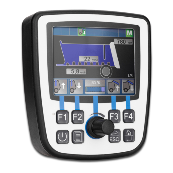
Product description | 3 3 Product description The JVM-104-O09 is a graphical HMI. Thanks to its compact design and inte- grated controller, the HMI is versatile and has been specially developed for harsh applications in commercial vehicles and self-propelled machines. -
Page 9: Nameplate
Jetter AG Product description | 3 3.3 Nameplate Fig. 2: Nameplate Logo Serial number Article number and hardware re- Barcode vision Model code number 3.4 Scope of delivery Scope of delivery Item number Quantity JVM-104-O09 10001559 JVM-104-O09 User Manual 9 / 62... -
Page 10: Technical Specifications
3x 24 h Shock resistance Type of shock Half-sine wave DIN EN 60068-2-27 Intensity and duration 30 g (300 m/s ) for 18 ms Number and direction 18 shocks in all 6 direc- tions JVM-104-O09 User Manual 10 / 62... -
Page 11: Environmental Conditions
250 kBaud … 1 MBaud ® Protocol CANopen Default node ID on 127 (0x7F) the CANopen® bus Terminating resistor Does not exist. Must be connected externally. Cable specification Twisted pair conductors, unshielded Tab. 6: CAN interface specification JVM-104-O09 User Manual 11 / 62... -
Page 12: Multi-Purpose Inputs/Outputs
Input resistance 50 kΩ Resolution 12 bits Electrical isolation None Tab. 11: Technical data - Voltage measurement Current measure- Category Description ment Measuring range DC 0 mA ... DC 20 mA Measuring shunt 120 Ω JVM-104-O09 User Manual 12 / 62... -
Page 13: Tab. 12 Technical Data - Current Measurement
Description Maximum output current per 2.5 A channel Rated voltage Supply voltage VBAT_PA Diagnostics Overcurrent, short circuit, cable break Overcurrent evaluation Adjustable current trip Maximum latency: Switch- 500 ms ing between output and in- JVM-104-O09 User Manual 13 / 62... -
Page 14: Emi Values
(duty cycle) Diagnostics Overcurrent Tab. 18: Technical data – H-bridge 4.9 EMI values The JVM-104-O09 has E1 approval according to ECE R10 Rev. 5 and CE con- formity according to ISO 14982. Pulses to ISO Test pulse Values Functional class 7637-2 -450 V... -
Page 15: Tab. 19 Pulses To Iso 7637-2
Tab. 20: Irradiation to ISO 11452 ESD EN 61000-4-2 ESD EN 61000-4-2 Values Functional class Contact discharge ±4 kV (to conductive sur- faces) Discharge through air ±8 kV (to insulating sur- faces) Tab. 21: ESD EN 61000-4-2 JVM-104-O09 User Manual 15 / 62... -
Page 16: Mechanical Installation
Installation location close to heat-sensi- The materials could become warped or tive materials misshapen as a result of heat produced by the device. Tab. 22: Unsuitable installation locations JVM-104-O09 User Manual 16 / 62... -
Page 17: Preparing For Installation
10001551 consisting of mounting plate and screws for housings with Deutsch/M12 connector including RAM Mount arm with suc- tion cup Tab. 23: Mounting accessories Screw holes Fig. 5: All dimensions of screw holes are in millimeters. JVM-104-O09 User Manual 17 / 62... -
Page 18: Installing The Hmi
Mount ball Screw the desired RAM Mount attachments onto the mounting plate. Hold the JVM-104-O09 against the mounting plate from behind. The connec- tors must be accessible through the openings in the mounting plate. Screw the mounting plate onto the JVM-104-O09. -
Page 19: Mounting The Hmi Combined With Jxm-Hmi
2 x self-locking nuts Screw the desired RAM Mount attachments onto the mounting plate. Hold the JVM-104-O09 and the JXM-HMI against the mounting plate from be- hind. The connectors must be accessible through the openings in the mount- ing plate. -
Page 20: Fig. 9 Installing The Strain Relief
Ensure that there is sufficient clearance between the strain reliefs and the con- nectors. ■ Connectors must not be obstructed, so that they can be removed in the event of service. Fig. 9: Installing the strain relief JVM-104-O09 User Manual 20 / 62... -
Page 21: Electrical Connection
Surges resulting from missing protection or fusing Surges may cause malfunctions or damage to the product. ► Protect the voltage inputs from surges according to the requirements. ► Ensure that the device is handled in accordance with ESD regulations. JVM-104-O09 User Manual 21 / 62... -
Page 22: Pin Assignment Of Deutsch Connector
Therefore, dimension the size of the wire for pin 7 accordingly. INFO Ignition To launch the JVM-104-O09, pin 8 (Ignition+) must be connected with pin 6. The ignition control signal (Ignition+) is connected with the key position Ignition ON. INFO... -
Page 23: Wiring - Example
Wire size range 1.0 ... 1.5 mm2 (AWG 18 ... 16) 6.2 Wiring - Example The following examples shows how to connect a JVM-104-O09. Fig. 12: Wiring - Example Output, e.g. lamp Output to control a motor Power supply (battery) -
Page 24: Programming
Format of numerical val- Notation Keyword Var, When, Task Commands BitClear(); Constant numerical values 100 0x100 0b100 Comment // This is a com- ment Further program processing // ... Tab. 28: JetSym sample programs JVM-104-O09 User Manual 24 / 62... -
Page 25: Canopen® Stx Api
CiA DS 4xx - These documents describe the behavior of a number of device classes in, what are known as, device profiles. 7.2.1 STX Functions Application STX functions are used in the communication between the JVM-104-O09 and ® other CANopen nodes. -
Page 26: Canopen® Object Dictionary
Jetter AG Programming | 7 7.2.2 CANopen® Object dictionary The operating system of the JVM-104-O09 supports the following objects: Index Object Type of Object name Data type (hex) (code) access 1000 Device type Unsigned32 RO (read only) 1001 Error Register... -
Page 27: Directories
By JetSym ■ By means of file commands from within the application program 7.4.4 Application program memory By default, the application program is uploaded from JetSym to the JVM-104-O09 and is stored there. Properties ■ Stored as file within the file system ■... -
Page 28: Flash Disk
Non-volatile ■ Quantity: 256 ■ Flag numbers: 0 ... 255 Properties ■ Global variables which are assigned to permanent addresses (%MX) of overlaid ■ Non-volatile user flags ■ Overlaid by registers 1000000 ... 1000055 JVM-104-O09 User Manual 28 / 62... -
Page 29: Controls And Ignition
[POWER], [SCROLL], [ESC]and [HOME]. These input keys are user-program- mable. Special registers In register 361000 of the JVM-104-O09 a bit-coded map of the input keys is avail- able. You can use this map for programming. The following registers are available for programming the input keys:... -
Page 30: Digipot
[HOME] 0x24 Tab. 31: Virtual key codes 7.5.2 Digipot The JVM-104-O09 has a rotary dial (digipot) with pushbutton feature which offers a convenient input option. The following provides details of the digipot's special registers with a corresponding sample program. Digipot registers... -
Page 31: Ignition And Off Delay
Programming | 7 7.5.3 Ignition and OFF delay This chapter covers the ignition and the function Shutdown(). Special registers The special register 361100 of the JVM-104-O09 is responsible for prompting the state of the ignition. Where: If … … then …... -
Page 32: Multi-Purpose Inputs
6010x0002 Analog value in µA/mV 6010x0003 Frequency [gate time]/period [μs]/count value [in- crements] 6010x0004 Digital value of the active-high input 6010x0005 Gate time in ms within frequency metering Tab. 33: Register overview - Multi-purpose inputs JVM-104-O09 User Manual 32 / 62... -
Page 33: Status And Instructions
0101 = Period time measuring, 1 s timeout 0110 = Period time measuring, 100 ms timeout Bit 9 Voltage measuring Current measurement Bit 12 Activate pull-up resistor Deactivate pull-up resistor Tab. 35: Command register for multi-purpose input MFQEx, bit-coded JVM-104-O09 User Manual 33 / 62... -
Page 34: Analog Functions
Jetter AG Programming | 7 7.6.2 Analog functions The multi-purpose inputs of the JVM-104-O09 provide the following analog fea- tures: ■ Voltage measuring ■ Current measurement R 6010x0002 Analog value MFQEx The register value results from measuring the analog value at multi-purpose input... -
Page 35: Digital Functions
Jetter AG Programming | 7 7.6.3 Digital functions The multi-purpose inputs of the JVM-104-O09 provide the following digital fea- tures: ■ Digital input ■ Frequency measuring ■ Counting mode R 6010x0003 Frequency value of MFQEx Depending on the configuration, this register displays the frequency, the period or a count value of the multi-purpose input x. -
Page 36: Multi-Purpose Outputs
PWM pulse control factor (duty cycle) in steps of 0.1 % 6010x0005 Measured current of output PAx in mA 6010x0006 PWM frequency in Hz 6010x0007 Adjustable overcurrent limit in mA Tab. 41: Register overview - Multi-purpose inputs JVM-104-O09 User Manual 36 / 62... -
Page 37: Status And Instructions
Output PAx as low-side output 10 = Output PAx as high-side output 11 = Output PAx as low-side output Bit 15 Activate output Deactivate output Tab. 43: Command register for multi-purpose outputs PA1 to PA4, bit-coded JVM-104-O09 User Manual 37 / 62... -
Page 38: Analog Functions
Set the limit of the overcurrent: R 6010x0007 := 1,000; Activate the output as digital output and, for example, as low-side output: R 6010x0001 := 0x0004; Retrieve the current from R 6010x0005 in mA. JVM-104-O09 User Manual 38 / 62... -
Page 39: Digital Functions
Jetter AG Programming | 7 7.7.3 Digital functions The multi-purpose outputs of the JVM-104-O09 provide the following digital fea- tures: ■ Digital input ■ Digital output ■ PWM output R 6010x0002 PWM duty cycle This register lets you set the value of the PWM pulse control factor while the PWM output is active. -
Page 40: Multi-Purpose Outputs Pa3 And Pa4 Functioning As H-Bridges
Tab. 49: Dither function - Setting the width of the dither signal in percent 7.7.4 Multi-purpose outputs PA3 and PA4 functioning as H-bridges The JVM-104-O09 lets you control multi-purpose outputs PA3 and PA4 as H- bridges. To control an output as H-bridge, the program must include the following steps: Clockwise rotation Activate the low-side output of PA3. - Page 41 Tab. 55: System time base in milliseconds R 201005 System time base in microseconds Every microsecond this register is incremented by 1. Property Description Values -2,147,483,648 ... (overflowing) 2,147,483,647 Type of access Read Tab. 56: System time base in microseconds JVM-104-O09 User Manual 41 / 62...
-
Page 42: Operating System Update
To activate the newly installed OS, re-boot the device. 7.9.2 Performing an OS update via JetEasyDownload To update the operating system of a JVM-104-O09 use a Peak CAN dongle and the command line tool JetEasyDownload (version 1.00.0.15 or higher) by Jetter. -
Page 43: Application Program
JVM-104-O09, the application program is loaded via the file system and exe- gram cuted. The application program is loaded by the OS of the JVM-104-O09 as follows: Level Description The operating system reads the file \App\start.ini from the internal flash disk. -
Page 44: Registers - Overview
Jetter AG Registers - Overview | 8 8 Registers - Overview This register overview describes the registers of the JVM-104-O09 in summa- rized form. 8.1 Default address on the CANopen® bus Default address of the JVM-104-O09: Node ID: 127 (0x7F) 8.2 General overview - Registers... -
Page 45: Electronic Name Plate (Device As A Whole)
Used memory in bytes 107522 Blocked memory in bytes 107523 Free memory in bytes 8.9 System information Register ranges Description 108500 ... 108509 JetVM-DII version string 108510 ... 108519 Version string of the host application JVM-104-O09 User Manual 45 / 62... -
Page 46: General System Registers
Password for system com- 0x424f6f74 mand register: 202961 System command register 202980 Error history: Number of entries 202981 Error history: Index 202982 Error history: Entry 203100 ... 203107 32-bit overlaying Flags 0 ... 255 JVM-104-O09 User Manual 46 / 62... -
Page 47: Application Program
210072 Manual triggering of a timer event (bit-coded) 210073 End of cyclic task (task ID) 210074 Command for cyclic tasks 210075 Number of timers 210076 Timer number (for R210077) 210077 Timer value in milliseconds JVM-104-O09 User Manual 47 / 62... -
Page 48: File System/Data File Function
Ignition is OFF Digipot 363000 Present count value 363001 Digipot key 363002 Minimum count value 363003 Maximum count value Illumination 64000 Background lighting 364001 Night-lighting of keys Visualization 365100 Language selection according to ID JVM-104-O09 User Manual 48 / 62... -
Page 49: Flag
1376 ... 1407 1000008 512 ... 543 1000036 1408 ... 1439 1000009 544 ... 575 1000037 1440 ... 1471 1000010 576 ... 607 1000038 1472 ... 1503 1000011 608 ... 639 1000039 1504 ... 1535 JVM-104-O09 User Manual 49 / 62... -
Page 50: System Functions
Reading a data file Deleting a data file System functions Corresponding JetSym STX function Function Bcd2Hex(Bcd: int): Int; Function Hex2Bcd(Hex: int): Int; Function QSort(DataPtr: Int, ElementCnt: Int, Element- Size: Int, SortOffset: Int, SortType: STXBASETYPE, SortMode: QSORTMODE): Int; JVM-104-O09 User Manual 50 / 62... - Page 51 Registers - Overview | 8 System functions Corresponding JetSym STX function 90/91 Function FileDAWrite(Const Ref FileName: String, Const Ref Mode: String, VarType: DAWRITE_TYPE, First: Int, Last: int): Int; Function FileDARead(Const Ref FileName: String): Int; JVM-104-O09 User Manual 51 / 62...
-
Page 52: Register Overview - Multi-Purpose Inputs And Outputs | 9
Register overview - Multi-purpose inputs and outputs | 9 9 Register overview - Multi-purpose inputs and outputs This register overview describes the registers of the multipurpose inputs and out- puts of the JVM-104-O09. 9.1 General overview - Registers Internal I/O board Register... -
Page 53: Multi-Purpose Input Mfqex
= 2 for multi-purpose output 2 (as of 601020000) Register Description 6010x0000 Status Bit 0 Overcurrent In current measurement mode triggered by a current > 2500 mA. Bit 7 Overtemperature Overtemperature is present Bit 14 Multi-purpose input MFQEx is ... enabled disabled JVM-104-O09 User Manual 53 / 62... -
Page 54: Multi-Purpose Outputs Pa1
Output PAx as PWM output Bit 3 … 2 00 = Output PAx as input 01 = Output PAx as low-side output 10 = Output PAx as high-side output 11 = Output PAx as low-side output JVM-104-O09 User Manual 54 / 62... - Page 55 Adjustable overcurrent limit in mA 6010x0010 Dither function - the xth pulse is superimposed Example: At value 2, every second pulse is overlaid. 6010x0011 Dither function - Width of the dither signal in ±0.1 % JVM-104-O09 User Manual 55 / 62...
-
Page 56: Maintenance And Repairs
In case of damaged packaging inspect the device for any visible damage, and in- form your freight forwarder and the Jetter AG of the damage caused during ship- ment. If the device is damaged or has been dropped, it is strictly forbidden to use... -
Page 57: Service
To contact them, please call our technical hotline or use the contact form on our homepage: Technical hotline | Jetter - We automate your success. You are also welcome to send an e-mail to our technical hotline: hotline@jetter.de... -
Page 58: Spare Parts And Accessories
Deutsch/M12 connector including RAM Mount arm with suc- tion cup Mounting plate for JVM-104-O09 combined with a JXM-HMI 10001832 for RAM Mount ball consisting of mounting plate and screws for housing with... - Page 59 Fig. 6 Installation drawing........................Fig. 7 Installing the strain relief......................Fig. 8 Installation drawing........................Fig. 9 Installing the strain relief......................Fig. 10 Deutsch connector, 12 pins..................... Fig. 11 H-bridges..........................Fig. 12 Wiring - Example ........................JVM-104-O09 User Manual 59 / 62...
- Page 60 Tab. 40 Description of the placeholder x ....................Tab. 41 Register overview - Multi-purpose inputs ................Tab. 42 Status register of the multi-purpose outputs PA1 … PA4 ............Tab. 43 Command register for multi-purpose outputs PA1 to PA4, bit-coded........JVM-104-O09 User Manual 60 / 62...
- Page 61 Tab. 53 Application time base in application time base units ............... Tab. 54 Application time base units for R 201002................Tab. 55 System time base in milliseconds ................... Tab. 56 System time base in microseconds..................Tab. 57 Accessories ..........................JVM-104-O09 User Manual 61 / 62...
- Page 62 Jetter AG Graeterstrasse 2 71642 Ludwigsburg www.jetter.de E-mail info@jetter.de Phone +49 7141 2550-0 We automate your success.
Need help?
Do you have a question about the JVM-104-O09 and is the answer not in the manual?
Questions and answers