Advertisement
Available languages
Available languages
Quick Links
Jetter AG
Gräterstraße 2
D-71642 Ludwigsburg
Germany
Artikel-Nr.: 60875009 / Dezember 2011 / Printed in Germany
1 x
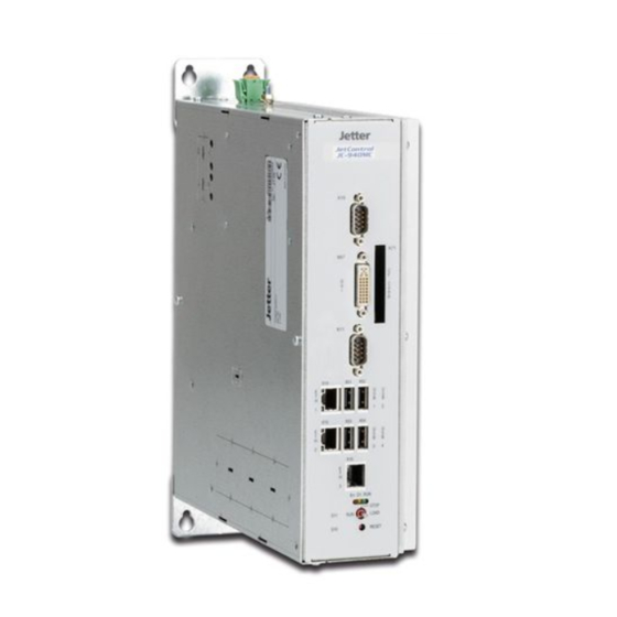
JC-940MC
1 x
60875009
JC-940MC
Steuerung
Kontakte:
E-Mail - Vertrieb:
E-Mail - Hotline:
Telefon - Hotline:
Installationsanleitung
Version 1.01
Lieferumfang
Optionen: -[16 | 24] -[E]
Installationsanleitung
sales@jetter.de
hotline@jetter.de
+49(0)7141/2550-444
Advertisement

Subscribe to Our Youtube Channel
Related Manuals for Jetter JC-940MC


Summary of Contents for Jetter JC-940MC
- Page 1 JC-940MC Steuerung Jetter AG Kontakte: Gräterstraße 2 E-Mail - Vertrieb: sales@jetter.de D-71642 Ludwigsburg E-Mail - Hotline: hotline@jetter.de Germany Telefon - Hotline: +49(0)7141/2550-444 Installationsanleitung Version 1.01 Artikel-Nr.: 60875009 / Dezember 2011 / Printed in Germany Lieferumfang JC-940MC Optionen: -[16 | 24] -[E]...
- Page 2 Maße der Befestigungsbohrungen R 2,5 EINZELHEIT A...
- Page 3 IP-Adresse einstellen Schritt Vorgehen Schalten Sie den JC-940MC ein und warten Sie bis das Be- triebssystem vollständig gestartet hat. Stellen Sie eine Ethernet-Verbindung zwischen Ihrem PC und dem JC-940MC her. Starten Sie auf Ihrem PC JetSym oder JetIPScan. Wählen Sie die gewünschte Steuerung aus der Liste aus.
- Page 4 LEDs der Steuerung Farbe Bedeutung Betriebssystem läuft grün Spezielle Zustände gelb Fehler LED-Zustände der Steuerung in der Bootphase Stufe Beschreibung Reset Initialisierung der Laufzeitumgebung des Anwenderprogramms und der Echtzeitkommunikation Start Motion Control Initialisierung der Zusatzfunktionen (Web, Modbus/TCP usw.) Normaler Betriebszustand, das An- wenderprogramm läuft nicht.
- Page 5 RESET Durch Drücken des Tasters wird ein LOAD Hardware-Reset der Steuerung aus- geführt RESET Stellung Funktion Steuerung JC-940MC startet nach dem Einschalten das Anwenderpro- gramm. STOP Steuerung JC-940MC startet nicht das Anwenderprogramm nach dem Einschalten. LOAD Steuerung JC-940MC startet nicht das Anwenderprogramm nach dem Einschalten.
- Page 6 Anschlussbeschreibung X10 Klemmpunkt Funktion X10.DC24V Versorgungsspannung für 2,2A Steuerung JC-940MC X10.0V Bezugspotenzial Technische Daten X10 Spannungsbereich: DC 24 V, -15 % ... +20 % Leistungsaufnahme: max. 2,2 A x 24,0 V = 53 W Leiteranschluss X10 Technologie: Schraubanschluss Schraubendreher: SZS 0,6 x 3,5 AWG: 12 ...
- Page 7 Anschlussbeschreibung X14 Teil Funktion Buchse X14, Ethernet Port LED LINK: X14 mit einem Ethernet verbunden LED ACT: JC-940MC sendet oder empfängt über X16 Technische Daten X14 Übertragungsrate: 10 MBit/s, 100 MBit/s, 1.000 MBit/s auto cross over: Klemmenart: RJ45-Buchse Leitungsart: Cat 5e (10/100 MBit/s); Cat 6...
-
Page 9: Installation Instruction
JC-940MC Controller Jetter AG Contacts: Graeterstrasse 2 E-Mail - Sales: sales@jetter.de D-71642 Ludwigsburg E-Mail - Hotline: hotline@jetter.de Germany Phone - Hotline: +49(0)7141/2550-444 Installation Instruction Revision 1.01 Item # 60875009 / December 2011 / Printed in Germany Scope of Delivery JC-940MC... - Page 10 Dimensions of Mounting Holes R 2,5 EINZELHEIT A...
-
Page 11: Setting The Ip Address
Setting the IP Address Step Action Power up the JC-940MC and wait until the OS has been launched. Establish an Ethernet connection between PC and JC-940MC. Launch JetSym or JetIPScan on your PC. Select the desired controller from the list. -
Page 12: Leds Of The Controller
LEDs of the Controller Color Description OS is running green Special conditions amber Error LED Conditions of the Controller During Boot Process Step Description Reset Initializing the runtime environment of the user program and realtime communication Motion Control Start Initializing additional functions (Web, Modbus/TCP etc.) Normal operating condition, application program is not running. - Page 13 RESET Function Positions of Mode Selector Once the controller JC-940MC is powered up, the application program will be launched. STOP Once the controller JC-940MC is powered up, the application program will not be launched.
- Page 14 Description of Terminal X10 Terminal Function point X10.DC24V Power supply for controller 2.2A JC-940MC X10.0V Reference potential Technical Data X10 Voltage range: DC 24 V, -15 % ... +20 % Power consumption: max. 2.2 A x 24.0 V = 53 W...
- Page 15 Description of Connections X14 Number Function Terminal X14, Ethernet port LED LINK: X14 is connected with Ethernet LED ACT: JC-940MC is transmitting or receiving signals via X14 Technical Data X14 Bit rate: 10 Mbit/s, 100 Mbit/s, 1,000 Mbit/s Auto cross-over:...
Need help?
Do you have a question about the JC-940MC and is the answer not in the manual?
Questions and answers