Advertisement
Available languages
Available languages
Quick Links
Jetter AG
Gräterstraße 2
D-71642 Ludwigsburg E-Mail - Hotline:
Germany
Artikel-Nr.: 60880911 | Version 1.00
1 x
10001424 Steuerung: JetControl
1 x
60870409 2-poliger Stecker, Zugfederanschluss
10 x
60870411 Klemmenmarkierer
1 x
60880911 Installationsanleitung
JC-440
Steuerung
Kontakte:
E-Mail - Vertrieb: sales@jetter.de
Telefon - Hotline: +49(0)7141/2550-
Installationsanleitung
Mai 2016 / Printed in Germany
Laden Sie die Betriebsanleitung
von www.jetter.de unter Downloads
herunter.
Lieferumfang
hotline@jetter.de
444
Advertisement

Related Manuals for Jetter JC-440


Summary of Contents for Jetter JC-440
- Page 1 JC-440 Steuerung Jetter AG Kontakte: Gräterstraße 2 E-Mail - Vertrieb: sales@jetter.de D-71642 Ludwigsburg E-Mail - Hotline: hotline@jetter.de Germany Telefon - Hotline: +49(0)7141/2550- Installationsanleitung Artikel-Nr.: 60880911 | Version 1.00 Mai 2016 / Printed in Germany Laden Sie die Betriebsanleitung von www.jetter.de unter Downloads herunter.
- Page 2 Montage auf Hutschiene EN 50022 Schritt Vorgehen Setzen Sie die JC-440 auf die Hutschiene oben auf. Bewegen Sie die JC-440 in Pfeilrichtung, bis sie auf der Hutschiene einrastet. Die JC-440 sitzt nun fertig montiert auf der Hutschiene.
- Page 3 Einstellen der IP-Adresse Schritt Vorgehen Schalten Sie die Steuerung JC-440 spannungslos. Drücken Sie auf die obere und untere Rastlasche. Ziehen Sie das Gehäuse nach vorne ab. Auf dem Backplane-Modul sind nun die DIP-Schalter (1) erreichbar. Ändern Sie die IP-Adresse über die DIP-Schalter (1).
- Page 4 Default-IP-Adresse 1 2 3 4 5 6 7 8 9 10 11 12 Setzen Sie das Gehäuse wieder auf das Backplane-Modul. Versorgen Sie die JC-440 wieder mit Spannung. Weitere Informationen zum Einstellen der IP-Adresse entnehmen Sie der Betriebsanleitung. LEDs Farbe Beschreibung Betriebssystem läuft...
- Page 5 LED-Zustände beim Einschalten Stufe Beschreibung Reset Die Steuerung initialisiert das Betriebssystem. Das Betriebssystem liest den DIP-Schalter auf dem Backplane-Modul und prüft das Vorhandensein des Ethernet-Switches. Das Betriebssystem initialisiert Echtzeituhr, Ethernet-Schnittstelle und Dateisystem. Das Betriebssystem initialisiert die Module an den Systembussen und die Softwareteile (Web, Modbus/TCP usw.);...
- Page 6 Schalter S11 Stellung Beschreibung Steuerung JC-440 startet nach dem Einschalten das Anwendungsprogramm. LOAD STOP Steuerung JC-440 startet STOP nicht das Anwendungs- programm nach dem Einschalten. Steuerung JC-440 führt LOAD nach dem Einschalten die Datei autocopy.ini auf dem USB-Stick aus. Ist kein USB-Stick oder...
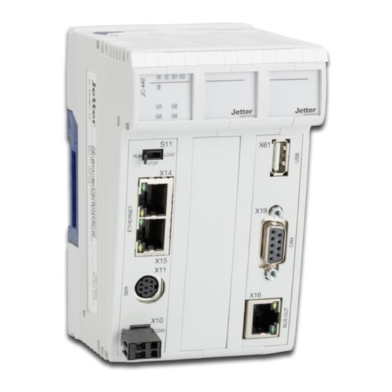
- Page 7 Anschlussbeschreibung X10 Klemmpunkt Beschreibung X10.DC24V Versorgungsspannung für Steuerung JC-440 und angeschlossene Peripheriemodule X10.0V Bezugspotenzial Technische Daten X10 Spannungsbereich: DC 24 V, -15 % ... +20 % Leistungsaufnahme: Max. 2,3 A x 24,0 V = 55,2 W Leiteranschluss X10 Technologie: Zugfederanschluss...
- Page 8 Anschlussbeschreibung X11 Signal Beschreibung RS-422, Rx invertiert Bezugspotenzial RS-422, Rx nicht invertiert RS-232; Rx RS-422, Tx nicht invertiert RS-485, Rx/Tx nicht invertiert DC24V Versorgungsspannung Bediengerät RS-422, Tx invertiert RS-485, Rx/Tx invertiert RS-232; Tx Technische Daten X11 Steckertyp: MiniDIN, 8-polig, geschirmt Spannung für Bediengerät Entspricht der Spannung an an X11.6:...
- Page 9 Steckertyp: Sub-D 9-polig, Buchse Hinweise zur EMV Beachten Sie die Application Note 016 EMV-gerechte Schaltschrankinstallation, die die Jetter AG erstellt hat. Hinweis Die Application Note 016 finden Sie im Download- bereich auf unserer Homepage http://www.jetter.de. Weitere Informationen entnehmen Sie der...
- Page 10 Nummer Beschreibung Buchse X14, Ethernet-Port Buchse X15, Ethernet-Port LED LINK: X14 mit einem Ethernet verbunden LED ACT: JC-440 sendet oder empfängt über X14 LED LINK: X15 mit einem Ethernet verbunden LED ACT: JC-440 sendet oder empfängt über X15 Technische Daten X14/X15 Übertragungsrate:...
- Page 11 Anschlussbeschreibung X16 Nummer Beschreibung Buchse X16, Ethernet-Port (BUS OUT) LED LINK, gelb: X16 mit einem Ethernet verbunden LED ACT, grün: JC-440 sendet oder empfängt über Technische Daten X16 Übertragungsrate: 100 MBit/s Auto-crossover: Klemmenart: RJ45-Buchse Leitungsart: Cat 5e, geschirmt...
-
Page 12: Usb-Schnittstelle
USB-Schnittstelle Technische Daten USB-Schnittstelle Maximaler Ausgangsstrom: 0,5 A USB-Typ: Type A (Host) Spezifikation: USB 2.0 Vorschrift für den Anschluss des USB-Sticks Anschlussart: Aus EMV-Gründen ist der USB-Stick direkt zu stecken. Verlängern Sie den USB-Stick nicht über ein Kabel. - Page 13 JC-440 Controller Jetter AG Communication: Graeterstrasse 2 E-mail - Sales: sales@jetter.de D-71642 Ludwigsburg E-mail - Hotline: hotline@jetter.de Germany Phone - Hotline: +49(0)7141/2550- Installation Manual Item # 60880911 | Revision 1.00 May 2016 / Printed in Germany Download the user manual from www.jetter.de, Downloads.
- Page 14 Installation on DIN rail to EN 50022 Step Action Place the JC-440 on the upper edge of the DIN rail. Move the JC-440 in the direction of the arrow until it snaps into place. Installation of the JC-440 on the DIN rail is now...
- Page 15 Setting the IP address Step Action Remove power from the controller JC-440. Press the upper and lower latches. Pull off the enclosure. Now, the DIP switches (1) on the backplane module can be accessed. Set the IP address using the DIP switches (1).
- Page 16 1 2 3 4 5 6 7 8 9 10 11 12 Reinstall the enclosure on the backplane module. Restore power to the JC-440. For further information on setting the IP address, please refer to the user manual of the device.
- Page 17 LED states at power-up Step Description Reset The controller initializes the OS. The OS reads the settings of the DIP switch on the backplane module and checks whether an Ethernet switch exists. The OS initializes realtime clock, Ethernet interface and file system. The OS initializes the modules on the system bus, as well as software...
- Page 18 Mode selector S11 Position Description Once the JC-440 is turned on, it launches the application program. LOAD STOP Although the JC-440 is STOP turned on, it does not launch the application program. Once the JC-440 is turned LOAD on, it executes the file autocopy.ini which is...
- Page 19 Connector X10 - Description Terminal Description point X10.DC24V Power supply for the JC-440 and connected peripheral modules X10.0V Reference potential Technical specifications - X10 Input voltage range: DC 24 V -15 % ... +20 % Power consumption: 2.3 A x 24.0 V = 55.2 W max.
- Page 20 Connector X11 - Description Signal Description RS-422, Rx inverted Reference potential RS-422, Rx not inverted RS-232; Rx RS-422, Tx not inverted RS-485, Rx/Tx not inverted DC24V HMI supply voltage RS-422, Tx inverted RS-485, Rx/Tx inverted RS-232; Tx Technical specifications - X11 Connector type: MiniDIN, 8-pin, shielded Voltage for the HMI at X11.6: It corresponds to the...
-
Page 21: Instructions On Emi
Instructions on EMI Also refer to Application Note 016 EMC-compatible installation of electric cabinets by Jetter AG. Note For downloading the Application Note 016, please turn to our homepage http://www.jetter.de, Downloads. For further information please refer to the JC-440 user manual. - Page 22 Female connector X14, Ethernet port Female connector X15, Ethernet port LED LINK: X14 is connected with Ethernet LED ACT: JC-440 is transmitting or receiving signals via X14 LED LINK: X15 is connected with Ethernet LED ACT: JC-440 is transmitting or receiving...
- Page 23 Connector X16 - Description Number Description Female connector X16, Ethernet port (BUS OUT) LED LINK, amber: X16 is connected with the Ethernet LED ACT, green: JC-440 is transmitting or receiving data via X16 Technical specifications - X16 Bit rate: 100 MBit/s Auto cross-over:...
- Page 24 USB interface Technical data of the USB interface Maximum output current: 0.5 A USB type: Type A (host) Specification: USB 2.0 Rules for connecting the USB flash drive Type of connection: For EMC reasons, the USB flash drive must be connected directly.
Need help?
Do you have a question about the JC-440 and is the answer not in the manual?
Questions and answers