Table of Contents
Advertisement
Quick Links
Advertisement
Chapters
Table of Contents

Related Manuals for Jetter JVM-104-O09


Summary of Contents for Jetter JVM-104-O09
- Page 1 User Manual JVM-104-O09 60884730_01 We automate your success.
- Page 2 Any revisions and technical advancements of our products are not automatically made available in a revised document. Jetter AG shall not be liable for any errors either in form or content, or for any missing updates, as well as for any damage or detriment resulting from such failure.
-
Page 3: Table Of Contents
Installing the HMI ........................20 Mounting the HMI combined with JXM-HMI ................22 Electrical connection ......................... 24 Pin assignment ........................25 6.1.1 Deutsch connector – voltage supply, multi-purpose inputs/outputs, CAN, ignition..25 Wiring - Example ........................27 User Manual – JVM-104-O09... - Page 4 Digital functions ......................50 8.7.4 Multi-purpose outputs PA3 and PA4 functioning as H-bridges........52 Runtime registers........................53 Saving and loading an application program ................55 Registers - Overview......................... 56 10 Register overview - Multi-purpose inputs and outputs ..............64 User Manual – JVM-104-O09...
- Page 5 11 Maintenance ............................. 67 11.1 Repairs ............................ 67 11.2 Return and disposal......................... 67 11.3 Storage and shipment......................68 12 Service .............................. 69 12.1 Customer service........................69 13 Spare parts and accessories ......................70 13.1 Accessories ..........................70 User Manual – JVM-104-O09...
-
Page 6: Introduction
For information on new revisions of this document, visit the download area on our website. This document is not subject to any updating service. Start | Jetter - We automate your success. For further information refer to the following information products: ■... -
Page 7: Safety
The device conforms to the EU directive 2011/65/EU (RoHS 2). 2.2 Purpose 2.2.1 Intended use The JVM-104-O09 is intended for installation in commercial vehicles and self-pro- pelled machines. It is an HMI with integrated controller for exchange of data with peripheral devices. -
Page 8: Warnings Used In This Document
CAUTION Low risk Indicates a hazardous situation which, if not avoided, could result in minor or moderate injury. NOTICE Material damage Indicates a situation which, if not avoided, could result in mal- functions or material damage. User Manual – JVM-104-O09... -
Page 9: Product Description
Product description | 3 3 Product description The JVM-104-O09 is a graphical HMI. Thanks to its compact design and in- tegrated controller, the HMI is versatile and has been specially developed for harsh applications in commercial vehicles and self-propelled machines. -
Page 10: Nameplate
Digital active-low input, digital output up to 2.5 A, PWM output, H-bridge ■ Front/rear degree of protection: IP65/IP65 3.3 Nameplate Fig. 2: Nameplate Logo Serial number Barcode Article number and hardware revision Model code number 3.4 Scope of delivery Scope of delivery Item number Quantity JVM-104-O09 10001559 User Manual – JVM-104-O09... -
Page 11: Technical Data
Shock resistance Type of shock Half-sine wave DIN EN 60068-2-27 Intensity and duration 30 g (300 m/s ) for 18 ms Number and direction 18 shocks in all 6 direc- tions Degree of protection Front panel IP65 DIN EN 60529 Rear panel IP65 Tab. 1: Mechanical specifications User Manual – JVM-104-O09... -
Page 12: Electrical Properties
Parameter Description Wire cross-section 500 kBaud: 0.34 mm² … 0.50 mm 250 kBaud: 0.34 mm² … 0.60 mm Cable capacitance 60 pF/m max. Resistivity 500 kBaud: Max. 60 Ω/km 250 kBaud: Max. 60 Ω/km Number of cores Twisting CAN_L and CAN_H cables are twisted pairwise Tab. 4: Specification - CAN bus cable User Manual – JVM-104-O09... -
Page 13: Multi-Purpose Inputs/Outputs
Resolution 12 bits Electrical isolation None Tab. 8: Technical data - Voltage measurement Current measurement Parameter Description Measuring range DC 0 mA ... DC 20 mA Measuring shunt 120 Ω Resolution 12 bits Overcurrent trip Electrical isolation None Tab. 9: Technical data - Current measurement User Manual – JVM-104-O09... -
Page 14: Tab. 10 Technical Data - Frequency Measurement
Type of input Active-high input Nominal voltage VBAT_PA – 10 % Operating point ON Minimum DC 4.0 V Operating point OFF Maximum DC 1.6 V Internal pull-up resistor NAMUR: 1 kΩ, 8.2 V Electrical isolation None Tab. 12: Technical data – Digital input PAx User Manual – JVM-104-O09... -
Page 15: Tab. 13 Technical Data - Digital Output
Supply voltage VBAT Maximum output current 2.5 A Peak current ~5 A, max. 500 ms Current measuring accu- ±20 % racy Switching frequency (1/ 100 Hz ... 1 kHz period length) Frequency accuracy ±42 ns Resolution of duty cycle 0.1 % Diagnostics Overcurrent Tab. 15: Technical data – H-bridge User Manual – JVM-104-O09... -
Page 16: Environmental Conditions
50° from above, 70° from below Tab. 17: Technical data – display 4.6 Acoustic signal generator Parameter Description Type Loudspeaker Adjustable frequency and volume. Volume 83 dB 10 cm distance and res- onance frequency 2,670 Hz Tab. 18: Acoustic signal generator User Manual – JVM-104-O09... -
Page 17: Emi Values
Jetter AG Technical data | 4 4.7 EMI values The JVM-104-O09 has E1 approval according to ECE R10 Rev. 5 and CE con- formity according to ISO 14982. Pulses ISO 7637-2 Test pulse Values Function class -450 V 2 a +37 V +20 V 3 a -150 V... -
Page 18: Mechanical Installation
The device must be easily accessible to allow for service work. Space required for It should be possible to disconnect the connectors at any time. installation and service Fig. 4: Space requirements for installation work (in mm) User Manual – JVM-104-O09... -
Page 19: Preparing For Installation
Mounting plate for RAM mount arm with suction cup 10001551 consisting of mounting plate and screws for housings with Deutsch/M12 connector including RAM Mount arm with suction cup Screw holes Fig. 5: Screw holes, dimensions in mm User Manual – JVM-104-O09... -
Page 20: Installing The Hmi
Alternate position of the RAM Mount ball Screw the desired RAM Mount attachments onto the mounting plate. Hold the JVM-104-O09 against the mounting plate from behind. The connec- tors must be accessible through the openings in the mounting plate. Screw the mounting plate onto the JVM-104-O09. -
Page 21: Fig. 7 Installing The Strain Relief
■ Ensure that there is sufficient clearance between the strain reliefs and the connectors. ■ Connectors must not be obstructed, so that they can be removed in the event of service. Fig. 7: Installing the strain relief User Manual – JVM-104-O09... -
Page 22: Mounting The Hmi Combined With Jxm-Hmi
JXM-HMI JVM-104-O09 2 x countersunk screws for mounting a RAM Mount ball Mounting plate with opening for connector 8 x screws for fixing the mounting plate to the JVM-104-O09 and JXM-HMI RAM Mount ball 2 x self-locking nuts Screw the desired RAM Mount attachments onto the mounting plate. -
Page 23: Fig. 9 Installing The Strain Relief
■ Ensure that there is sufficient clearance between the strain reliefs and the connectors. ■ Connectors must not be obstructed, so that they can be removed in the event of service. Fig. 9: Installing the strain relief User Manual – JVM-104-O09... -
Page 24: Electrical Connection
Surges resulting from missing protection or fusing Surges may cause malfunctions or damage to the product. ► Protect the voltage inputs from surges according to the requirements. ► Ensure that the device is handled in accordance with ESD regulations. User Manual – JVM-104-O09... -
Page 25: Pin Assignment
Therefore, dimension the size of the wire for pin 7 accordingly. INFO Ignition To launch the JVM-104-O09, pin 8 (Ignition+) must be con- nected with pin 6. The ignition control signal (Ignition+) is con- nected with the key position Ignition ON . INFO... -
Page 26: Fig. 11 H-Bridges
Compatible mating parts for the 12-pin DEUTSCH connector are as follows: Parameter Description Manufacturer Deutsch Manufacturer item DT06-12S number – housing Manufacturer item W12S number – wedge lock Manufacturer item 0-462-201-16141 number – crimp contact (receptacle) Wire size range 1.0 mm² ... 1.5 mm² (AWG 18 ... 16) User Manual – JVM-104-O09... -
Page 27: Wiring - Example
Jetter AG Electrical connection | 6 6.2 Wiring - Example The following example shows how to wire a JVM-104-O09. Fig. 12: Wiring example Output, e.g. lamp Output to control a motor Power supply (battery) Ignition lock Output to control the display LEDs Input, e.g. -
Page 28: Identification And Configuration
Start | Jetter - We automate your success. 7.1.1 Operating system update of the HMI This chapter describes how to update the operating system of a JVM-104-O09 HMI. There are several options to transfer the operating system file to the HMI: ■... -
Page 29: Tab. 23 Jeteasydownload Parameters
Identification and Configuration | 7 7.1.1.2 OS update via JetEasyDownload To update the operating system of this device, use a PEAK CAN dongle and the Jetter command line tool JetEasyDownload (version 1.00.0.15 or higher). JetEasyDownload To call JetEasyDownload you need specific parameters. Parameters... - Page 30 ü JetEasyDownload and PEAK CAN dongle are ready for use. ü There is a CAN connection between PEAK CAN dongle and JVM-104-O09. Call up JetEasyDownload with the above parameters and a valid OS file. ð The device carries out a reset.
-
Page 31: File System
\Data Folder for storing data \Windows Windows CE system directory RAM disk drive INFO Further information For more information on this subject refer to the application- oriented manual File System available for download from our homepage. User Manual – JVM-104-O09... -
Page 32: Features
Directory and file names with a length of up to 63 characters are possible. ■ All characters except "/" and ".." are permitted for directory and file names. ■ The location of the directories "App" and "Data" is on the flash disk drive. User Manual – JVM-104-O09... -
Page 33: Programming
The notation for sample programs used in this document is listed in the table be- programs low: Notation Format of numerical values Keyword Var, When, Task Commands BitClear(); Constant numerical values 100 0x100 0b100 Comment // This is a comment Further program processing // ... Tab. 27: JetSym sample programs User Manual – JVM-104-O09... -
Page 34: Canopen Stx Api
For more information on this subject refer to the application- oriented manual CANopen STX API available for download from our homepage. 8.2.1 STX Functions Application STX functions are used to enable communication between the JVM-104-O09 and other CANopen nodes. The JVM-104-O09 supports the following STX functions: Function Description... -
Page 35: Canopen Object Directory
INFO Further information For more information on this subject, refer to the JetSym Online Help. 8.2.2 CANopen object directory The operating system of the JVM-104-O09 supports the following objects: Index Object Object name Data type Access (hex) -
Page 36: Storage Options - Overview
8.3 Storage options - Overview The JVM-104-O09 features several types of program and data memory. There is volatile and non-volatile memory. Volatile memory loses its content at switching off. Non-volatile memory keeps its content even when the power supply is off. -
Page 37: Application Program Memory
Jetter AG Programming | 8 8.3.3 Application program memory By default, the application program is uploaded from JetSym to the JVM-104-O09 and is stored there. Properties ■ Stored as file within the file system ■ Default directory \app\program name Type of access ■... -
Page 38: Storing Registers And Variables
Variables of the application program can be stored to volatile memory. (non-remanent) Global variables that do not have a static assignment to addresses and are memory stored compactly. Their register number starts with the value 0. User Manual – JVM-104-O09... -
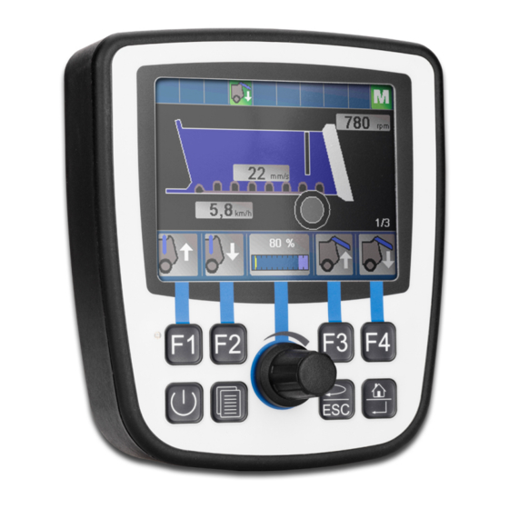
Page 39: Control Elements
[POWER], [SCROLL], [ESC]and [HOME]. These input keys are user-program- mable. Special registers In register 361000 of the JVM-104-O09 a bit-coded map of the input keys is avail- able. You can use this map for programming. The following registers are available for programming the input keys:... -
Page 40: Digipot
[HOME] 0x24 Tab. 30: Virtual key codes 8.4.2 Digipot The JVM-104-O09 has a rotary dial (digipot) with pushbutton feature which offers a convenient input option. The following provides details of the digipot's special registers with a corresponding sample program. Register Register... -
Page 41: Ignition And Off Delay
Online Help. 8.5 Ignition and OFF delay This chapter covers the ignition and the function Shutdown(). Special registers The special register 361100 of the JVM-104-O09 is responsible for prompting the state of the ignition. Where: If … … then …... - Page 42 Shutdown() function has the value false. This means that the device will switch off. Ignition: Int At %VL 361100; End_Var; Task Ign Autorun Loop When Ignition Continue; Delay(3000); Shutdown(False); End_Loop; End_Task; INFO Further information For more information on this subject, refer to the JetSym On- line Help. User Manual – JVM-104-O09...
-
Page 43: Multi-Purpose Inputs
6010x0001 Command (bit-coded) 6010x0002 Analog value in µA/mV 6010x0003 Frequency [gate time]/period [μs]/count value [increments] 6010x0004 Digital value of the active-high input 6010x0005 Gate time in ms within frequency metering Tab. 32: Register overview – multi-purpose inputs User Manual – JVM-104-O09... -
Page 44: Status And Instructions
0101 = Period time measuring, 1 s timeout 0110 = Period time measuring, 100 ms timeout Bit 9 Voltage measuring Current measurement Bit 12 Deactivate pull-up resistor Activate pull-up resistor Tab. 34: Command register for multi-purpose input MFQEx, bit-coded User Manual – JVM-104-O09... -
Page 45: Analog Functions
Jetter AG Programming | 8 8.6.2 Analog functions The multi-purpose inputs of the JVM-104-O09 provide the following analog fea- tures: ■ Voltage measuring ■ Current measurement R 6010x0002 Analog value MFQEx The register value results from measuring the analog value at multi-purpose input... -
Page 46: Digital Functions
Jetter AG Programming | 8 8.6.3 Digital functions The multi-purpose inputs of the JVM-104-O09 provide the following digital fea- tures: ■ Digital input ■ Frequency measuring ■ Counting mode R 6010x0003 Frequency value of MFQEx Depending on the configuration, this register displays the frequency, the period or a count value of the multi-purpose input x. -
Page 47: Multi-Purpose Outputs
Multi-purpose output PA2 Multi-purpose output PA3 Multi-purpose output PA4 Tab. 39: Description of the placeholder x Example x = 5 for multi-purpose output PA3. To activate the digital output of PA3 enter command 0x0008 into R 601050001. User Manual – JVM-104-O09... -
Page 48: Status And Instructions
Overtemperature is present. Bit 14 Multi-purpose output is ... enabled disabled Bit 15 Hardware protection has tripped Hardware protection has tripped due to over- current/short circuit. Tab. 41: Status register of the multi-purpose outputs PA1 … PA4 User Manual – JVM-104-O09... -
Page 49: Analog Functions
PAx is disabled and bit 0 is set in R 6010x0000. Property Description Values 0 ... 2500 Unit Milliamps Value after reset 0 represents a maximum current of 2.5 A Tab. 44: Adjustable overcurrent limit for the output PAy User Manual – JVM-104-O09... -
Page 50: Digital Functions
Activate the output as digital output and, for example, as low-side output: R 6010x0001 := 0x0004; Retrieve the current from R 6010x0005 in mA. 8.7.3 Digital functions The multi-purpose outputs of the JVM-104-O09 provide the following digital fea- tures: ■ Digital input ■... - Page 51 This register lets you set the width of the dither signal. Value 100 corresponds to ± 10 %. Property Description Value for input 0 … 1000 Unit ±0.1 % Tab. 48: Dither function - Setting the width of the dither signal in percent User Manual – JVM-104-O09...
-
Page 52: Multi-Purpose Outputs Pa3 And Pa4 Functioning As H-Bridges
Jetter AG Programming | 8 8.7.4 Multi-purpose outputs PA3 and PA4 functioning as H-bridges The JVM-104-O09 lets you control multi-purpose outputs PA3 and PA4 as H-bridges. To control an output as H-bridge, the program must include the following steps: Clockwise rotation Activate the low-side output of PA3. -
Page 53: Runtime Registers
Jetter AG Programming | 8 8.8 Runtime registers The JVM-104-O09 has several registers which are incremented by the operating system at regular intervals. These registers can be used to easily carry out time measurements in the application program. Overview of registers... - Page 54 Access Read Tab. 54: System time base in milliseconds R 201005 System time base in microseconds Every microsecond this register is incremented by 1. Property Description Values -2147483648 ... 2147483647 (overflowing) Access Read Tab. 55: System time base in microseconds User Manual – JVM-104-O09...
-
Page 55: Saving And Loading An Application Program
JVM-104-O09, the application program is loaded via the file system and exe- cuted. The application program is loaded by the OS of the JVM-104-O09 as follows: Step Description The operating system reads the file \App\start.ini from the internal flash disk. -
Page 56: Registers - Overview
9 Registers - Overview Register Description This register overview gives a condensed sum- range mary of the registers of the JVM-104-O09 device running OS version 4.12.0.11. 0 ... 255 Application flags (non-volatile) 256 ... 2047 Overlaid by registers R 1000000... - Page 57 Available sectors Bit 8 Illegal jump 107511 Used sectors Bit 9 Illegal call 107512 Blocked sectors Bit 10 Illegal index 107513 Free sectors Bit 11 Illegal opcode 107520 … Byte statistics 107523 Bit 12 Division by 0 User Manual – JVM-104-O09...
- Page 58 Task ID in scheduler table 209701 ... Enabling system components 210070 Task ID (for R210071) 209739 210071 Timer number (0 ... 31) 210072 Manual triggering of a timer event (bit-coded) 210073 End of cyclic task (task ID) User Manual – JVM-104-O09...
- Page 59 361000.0 [F1] 203108 0 ... 15 361000.1 [F2] 203109 16 ... 31 361000.2 [F3] 203110 32 ... 47 361000.3 [F4] 203111 48 ... 63 361000.4 [POWER] 203112 64 ... 79 361000.5 [SCROLL] 203113 80 ... 95 User Manual – JVM-104-O09...
- Page 60 203142 2208 ... 2223 1000029 1184 ... 1215 203143 2224 ... 2239 1000030 1216 ... 1247 203144 2240 ... 2255 1000031 1248 ... 1279 203145 2256 ... 2271 1000032 1280 ... 1311 1000033 1312 ... 1343 User Manual – JVM-104-O09...
- Page 61 1000047 1760 ... 1791 1000048 1792 ... 1823 1000049 1824 ... 1855 1000050 1856 ... 1887 1000051 1888 ... 1919 1000052 1920 ... 1951 1000053 1952 ... 1983 1000054 1984 ... 2015 1000055 2016 ... 2047 User Manual – JVM-104-O09...
- Page 62 Arc tangent Exponential function Natural logarithm Absolute value Separation of digits before and after the decimal point Sorting register values Writing a data file Appending a data file Reading a data file Deleting a data file User Manual – JVM-104-O09...
- Page 63 Function QSort(DataPtr: Int, ElementCnt: Int, ElementSize: Int, SortOffset: Int, SortType: STXBASETYPE, SortMode: QSORTMODE): Int; 90/91 Function FileDAWrite(Const Ref FileName: String, Const Ref Mode: String, VarType: DAWRITE_TYPE, First: Int, Last: int): Int; Function FileDARead(Const Ref FileName: String): Int; User Manual – JVM-104-O09...
-
Page 64: Register Overview - Multi-Purpose Inputs And Outputs
Analog value in µA/mV The following tables provide a highly condensed summary of the registers of the multi-purpose in- 601020003 Frequency [gate time]/period [μs]/ puts and outputs of the JVM-104-O09. count value [increments] 601020004 Digital value at the input General overview - Registers... - Page 65 0 = Activate pull-up resistor 1 = Deactivate pull-up resistor 6010x0002 Analog value in mA/µA 6010x0003 Frequency [gate time]/period [μs]/ count value [increments] 6010x0004 Digital value at the input 6010x0005 Gate time in ms within frequency metering User Manual – JVM-104-O09...
- Page 66 Multi-purpose output is ... Example: At value 2, every 0 = enabled second pulse is overlaid. 1 = disabled 6010x0011 Dither function - Width of the Bit 15 Hardware protection has tripped dither signal in ±0.1 % User Manual – JVM-104-O09...
-
Page 67: Maintenance
Any liability for any damages resulting from the use of non-original parts and equipment is excluded. 11.2 Return and disposal How to dispose of Return your Jetter AG product to us for proper disposal. Visit our homepage waste equipment detailed information and to download the required Returns form. -
Page 68: Storage And Shipment
In case of damaged packaging inspect the device for any visible damage, and in- form your freight forwarder and the Jetter AG of the damage caused during ship- ment. If the device is damaged or has been dropped, it is strictly forbidden to use... -
Page 69: Service
To contact them, please call our technical hotline or use the contact form on our homepage: Technical hotline | Jetter - We automate your success. You are also welcome to send an e-mail to our technical hotline: hotline@jetter.de... -
Page 70: Spare Parts And Accessories
Only use accessories recommended by Jetter AG. 13.1 Accessories INFO Ordering accessories The accessories are not part of the scope of delivery. Suitable accessories can be obtained from Jetter AG. Accessories Item number Mounting plate for RAM Mount ball 10001621... - Page 71 Installation drawing........................22 Fig. 9 Installing the strain relief......................23 Fig. 10 Deutsch connector, 12 pins ....................... 25 Fig. 11 H-bridges ........................... 26 Fig. 12 Wiring example.......................... 27 Fig. 13 WEEE icon – crossed-out trash can ..................67 User Manual – JVM-104-O09...
- Page 72 Tab. 34 Command register for multi-purpose input MFQEx, bit-coded ......... Tab. 35 Analog value of multi-purpose input MFQEx ..............Tab. 36 Frequency value of multi-purpose input MFQEx .............. Tab. 37 Digital value at multi-purpose input MDQEx..............User Manual – JVM-104-O09...
- Page 73 Tab. 52 Application time base in application time base units ............Tab. 53 Application time base units for R 201002 ................. Tab. 54 System time base in milliseconds..................Tab. 55 System time base in microseconds .................. User Manual – JVM-104-O09...
- Page 74 Jetter AG Graeterstrasse 2 71642 Ludwigsburg www.jetter.de E-mail info@jetter.de Phone +49 7141 2550-0 We automate your success.
Need help?
Do you have a question about the JVM-104-O09 and is the answer not in the manual?
Questions and answers