Table of Contents
Advertisement
Quick Links
Advertisement
Chapters
Table of Contents

Related Manuals for Jetter JCM-501-E01


Summary of Contents for Jetter JCM-501-E01
- Page 1 User Manual JCM-501-E01 Mobile controller 60884486_01 We automate your success.
- Page 2 This document has been compiled by Jetter AG with due diligence based on the state of the art as known to them. Any revisions and technical advancements of our products are not automatically made available in a revised document. Jetter AG shall not be liable for any errors either in form or content, or for any missing updates, as well as for any damage or detriment resulting from such failure.
-
Page 3: Table Of Contents
6 Electrical connection........................ 20 Pin assignment .......................... 21 6.1.1 Deutsch connector – voltage supply, CAN, USB, RS-232 .......... 21 7 Identification and Configuration ..................... 22 Identification .......................... 22 7.1.1 EDS registers ........................ 22 7.1.2 Version registers...................... 22 User Manual – JCM-501-E01... - Page 4 Data files........................ 50 Saving and loading an application program ................ 51 9 Registers - Overview ........................ 52 10 Maintenance ............................ 58 10.1 Repairs ............................ 58 10.2 Return and disposal........................ 58 10.3 Storage and shipment ....................... 59 User Manual – JCM-501-E01...
- Page 5 Jetter AG Table of contents 11 Service ............................... 60 11.1 Customer service........................ 60 12 Spare parts and accessories ...................... 61 12.1 Accessories .......................... 61 User Manual – JCM-501-E01...
-
Page 6: Introduction
For information on new revisions of this document, visit the download area on our website. This document is not subject to any updating service. Start | Jetter - We automate your success. For further information refer to the following information products: ■... -
Page 7: Safety
Machinery Directive This device is no safety-related part as per Machinery Directive 2006/42/EC, and must, therefore, not be used for safety-relevant applications. This device is NOT intended for the purpose of personal safety, and must, therefore, not be used to protect persons. User Manual – JCM-501-E01 7 / 65... -
Page 8: Warnings Used In This Document
Indicates a hazardous situation which, if not avoided, could result in minor or moderate injury. NOTICE Material damage Indicates a situation which, if not avoided, could result in mal- functions or material damage. User Manual – JCM-501-E01 8 / 65... -
Page 9: Product Description
Product description | 3 3 Product description The JCM-501-E01 controller forms the heart of compact, distributed architec- tures. With its numerous interfaces, as well as the proven, powerful 32-bit CPU, it can be used in system solutions of simple to medium complexity. -
Page 10: Led Indicators
Jetter AG Product description | 3 3.3 LED indicators The JCM-501-E01 has 2 LEDs which can be configured by the user. Fig. 2: LED indicators LED D2 LED D1 3.3.1 Diagnostic capability via LEDs The color and status of the LEDs provide diagnostic options for various states. -
Page 11: Nameplate
Jetter AG Product description | 3 3.4 Nameplate Fig. 3: Nameplate Logo Serial number Barcode Article number and hardware revision Model code number 3.5 Scope of delivery Scope of delivery Item number Quantity JCM-501-E01 10001818 User Manual – JCM-501-E01 11 / 65... -
Page 12: Technical Data
Jetter AG Technical data | 4 4 Technical data This chapter contains electrical, mechanical data and operating data of the JCM-501-E01. 4.1 Dimensions 104.8 41.5 38.1 44.4 Fig. 4: Dimensions in mm User Manual – JCM-501-E01 12 / 65... -
Page 13: Mechanical Specifications
170 mA at DC 12 V sumption (VBAT_ECU) 90 mA at DC 24 V Power consumption Approx 2 W Integrated protective func- Reverse polarity protection, overvoltage, short volt- tions age pulses Permissible voltage range DC 8 V ... 32 V VBAT_ECU Tab. 2: Power supply VBAT_ECU User Manual – JCM-501-E01 13 / 65... -
Page 14: Ports And Interfaces
The maximum permitted cable length depends on the baud rate being used and the number of CANopen devices being connected. Max. cable length Max. stub length Total cable length Baud rate 500 kBaud 100 m 5 m 30 m 250 kBaud 250 m 10 m 60 m Tab. 5: Cable lengths User Manual – JCM-501-E01 14 / 65... -
Page 15: Environmental Conditions
10 % … 95 % DIN EN 61131-2 Pollution degree DIN EN 61131-2 Tab. 8: Environmental conditions 4.5 Acoustic signal generator Parameter Description Type Loudspeaker Adjustable frequency and volume. Volume 83 dB 10 cm distance and reso- nance frequency 2,670 Hz Tab. 9: Acoustic signal generator User Manual – JCM-501-E01 15 / 65... -
Page 16: Emi Values
Jetter AG Technical data | 4 4.6 EMI values The JCM-501-E01 has E1 approval according to ECE R10 Rev. 5 and CE con- formity according to ISO 14982. NOTICE The USB port does not meet the immunity requirements relevant for KBA E1 approval. -
Page 17: Mechanical Installation
Dirt and moisture can affect the electrical connections. ► Protect unused pins using blanking plugs. ► Protect all electrical connections with appropriate single wire seals. ► Clean the area around a connector prior to removing the mating connector. User Manual – JCM-501-E01 17 / 65... -
Page 18: Requirements For The Installation Location
Installation location close to The materials could become warped or mis- heat-sensitive materials shapen as a result of heat produced by the de- vice. Tab. 13: Unsuitable installation locations User Manual – JCM-501-E01 18 / 65... -
Page 19: Installing The Control
Ensure that there is sufficient clearance between the strain reliefs and the con- nectors. ■ Connectors must not be obstructed, so that they can be removed in the event of service. Fig. 7: Installing the strain relief User Manual – JCM-501-E01 19 / 65... -
Page 20: Electrical Connection
Surges may cause malfunctions or damage to the product. ► Protect the voltage inputs from surges according to the re- quirements. ► Ensure that the device is handled in accordance with ESD regulations. User Manual – JCM-501-E01 20 / 65... -
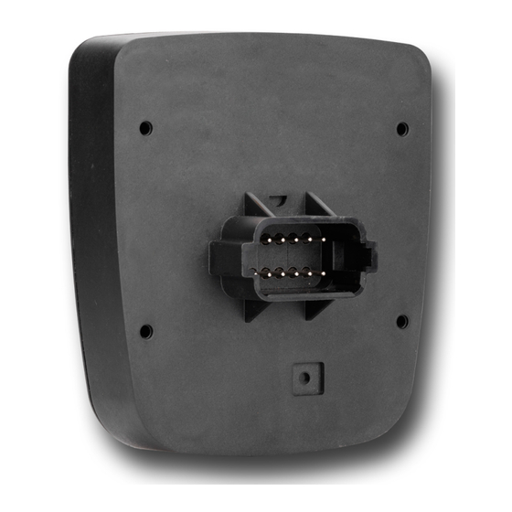
Page 21: Pin Assignment
Jetter AG Electrical connection | 6 6.1 Pin assignment 6.1.1 Deutsch connector – voltage supply, CAN, USB, RS-232 Function The Deutsch connector has the following functions: ■ Power supply to the JCM-501-E01 ■ CAN communication ■ ■ RS-232 INFO Current consumption When the device is energized, the current consumption is temporarily higher. -
Page 22: Identification And Configuration
The operating system provides several registers which can be used to read out the hardware revision or OS version of the device and its components. You will need this information when contacting the Jetter AG support hotline in case of a problem. -
Page 23: Operating System
From a USB flash drive ■ Via JetEasyDownload OS update from a USB flash drive A USB flash drive lets you transfer an OS file to the JCM-501-E01. Contents of the The batch file autostart.bat must have the following contents: batch file @echo off if not exist \App\autostart.exe goto end... - Page 24 Updating the OS An OS file for the JCM-501-E01 is available. ü The operating system of the JCM-501-E01 as of version 4.07.0.12 is running. ü The device remains powered on during the operating system update. Copy the OS file to your USB flash drive. This drive must be FAT formatted.
-
Page 25: Tab. 16 Jeteasydownload Parameters
Identification and Configuration | 7 OS update via JetEasyDownload To update the operating system of this device, use a PEAK CAN dongle and the Jetter command line tool JetEasyDownload (version 1.00.0.15 or higher). JetEasyDownload To call JetEasyDownload you need specific parameters. - Page 26 ü JetEasyDownload and PEAK CAN dongle are ready for use. ü There is a CAN connection between PEAK CAN dongle and JCM-501-E01. Call up JetEasyDownload with the above parameters and a valid OS file. ð The device carries out a reset.
-
Page 27: File System
RAM disk drive \USB Root directory of the USB flash drive INFO Further information For more information on this subject refer to the application-oriented manual File System available for download from our homepage. User Manual – JCM-501-E01 27 / 65... -
Page 28: Features
The following characters are not permitted in directory and file names: "/", "\", ":", "*", "?", "<", ">" and "|" ■ There is no user/access administration. Guarantee Jetter AG only guarantees for the proper functioning of USB flash drives option- ally available from Jetter AG. User Manual – JCM-501-E01 28 / 65... -
Page 29: Programming
Notation Format of numerical values Keyword Var, When, Task Commands BitClear(); Constant numerical values 100 0x100 0b100 Comment // This is a com- ment Further program processing // ... Tab. 20: JetSym sample programs User Manual – JCM-501-E01 29 / 65... -
Page 30: Canopen Stx Api
For more information on this subject refer to the application-oriented manual CANopen STX API available for download from our homepage. 8.2.1 STX Functions Application STX functions are used to enable communication between the JCM-501-E01 and other CANopen nodes. The JCM-501-E01 supports the following STX functions: Function... -
Page 31: Heartbeat Monitoring
Displaying information to the user ■ Rebooting the device ■ Ignoring process data INFO Further information For more information on this subject refer to the application-oriented manual CANopen STX API available for download from our homepage. User Manual – JCM-501-E01 31 / 65... -
Page 32: Canopen Object Directory
Jetter AG Programming | 8 8.2.3 CANopen object directory The operating system of the JCM-501-E01 supports the following objects: Object Index (Abbrevia- Object name Data type Access (hex) tion) 1000 Device type Unsigned32 RO (read only) 1001 Error Register Unsigned8... -
Page 33: Sae J1939 Stx Api
For more information on this subject refer to the application-oriented manual SAE J1939 STX API available for download from our homepage. 8.3.1 STX Functions Application STX functions are used in the communication between the JCM-501-E01 and other devices in a vehicle. The JCM-501-E01 supports the following STX functions: Function... - Page 34 SAEJ1939 function retrieves the currently set conversion GetSPNConversion() method. INFO Further information For more information on this subject refer to the application-oriented manual SAE J1939 STX API available for download from our homepage. User Manual – JCM-501-E01 34 / 65...
-
Page 35: Serial Interface Rs-232
Jetter AG Programming | 8 8.4 Serial interface RS-232 The JCM-501-E01 has a user-programmable RS-232 interface. 8.4.1 Operating principle The OS provides a receive buffer and a transmit buffer for the user-program- mable serial interface. These buffers can be used to adjust the transfer rate be- tween application program and serial interface. - Page 36 Parity error is set. The error counter is incremented. Buffer overflow A character is received, al- The character is discarded and er- though the receive buffer is ror bit Overflow is set. The error full. counter is incremented. User Manual – JCM-501-E01 36 / 65...
-
Page 37: Registers - Description
The registers of the interface are combined into one register block. The basic reg- ister number of this block is dependent on the device. Device Basic register number Register numbers JCM-501-E01 103100 103100 … 103119 Tab. 23: Register numbers of the serial interface User Manual – JCM-501-E01 37 / 65... -
Page 38: Tab. 25 Baud Rate
This register lets you set the number of stop bits per character. Property Description Values 1 stop bit 1.5 stop bits if MR 3 = 5 2 stop bits if MR 3 = 6, 7, 8 Value after reset Tab. 27: Stop bits User Manual – JCM-501-E01 38 / 65... -
Page 39: Tab. 28 Parity
Sending buffer filling level This register shows how many characters the sending buffer accommodates. There is space for 32,768 characters max. within the buffer. Property Description Values 0 ... 32,768 Tab. 31: Sending buffer filling level User Manual – JCM-501-E01 39 / 65... -
Page 40: Tab. 32 Receive Buffer, 8 Bits (Without Deleting The Character On Reading)
Receive buffer filling level This register shows how many characters the receive buffer accommodates. Each read access to MR 13 decrements this register by 1. Property Description Values 0 ... 32,768 Tab. 34: Receive buffer filling level User Manual – JCM-501-E01 40 / 65... -
Page 41: Tab. 35 Receive Buffer, 16-Bit, Little Endian
Bit 24 ... 31 Property Description Values -2,147,483,648 ... 2,147,483,647 Type of access Read Removes 4 characters from the buffer Takes effect if MR 14 > 3 Tab. 37: Receive buffer, 32-bit, little endian User Manual – JCM-501-E01 41 / 65... -
Page 42: Programming
Activating the serial interface Module register MR 7 lets you activate the user-programmable serial interface. ü Configuring the The JCM-501-E01 and the device to communicate with have been wired ac- interface cording to the RS-232 interface standard. ► Enter value 1 into MR 7. - Page 43 DisplayText2() (refer to the online help which comes with JetSym). Use the instruction DisplayText() or DisplayText2(). Specify Device 9. ð The task waits at this instruction until all characters have been entered into the transmit buffer. User Manual – JCM-501-E01 43 / 65...
-
Page 44: Real-Time Clock
The real-time clock has no automatic daylight savings time function. The JCM-501-E01 has a built-in battery with a service life of at least 10 years. User Manual – JCM-501-E01... -
Page 45: Storage Options - Overview
Programming | 8 8.6 Storage options - Overview The JCM-501-E01 features several types of program and data memory. There is volatile and non-volatile memory. Volatile memory loses its content at switching off. Non-volatile memory keeps its content even when the power supply is off. -
Page 46: Flag
Variables of the application program can be stored to volatile memory. (non-remanent) Global variables that do not have a static assignment to addresses and are memory stored compactly. Their register number starts with the value 0. User Manual – JCM-501-E01 46 / 65... -
Page 47: Automatic Copying Of Controller Data
This chapter describes the Autostart feature allowing for data to be copied within the JCM-501-E01. To this end, you can create a command file which is then stored along with the data to a USB flash drive. This command file is then auto- matically processed when the USB flash drive is inserted. -
Page 48: Loading The Autostart Function
8.7.2 Executing the AutoStart function During the boot phase in autostart mode, the device executes the commands in the command file. Executing the The operating system of the JCM-501-E01 processes the autostart function in the Autostart function following steps: Step Description The file \USB\autostart.bat is loaded from the USB stick. -
Page 49: Example Of A Command File
The commands correspond to common Windows command line syntax. commands 8.7.5 Example of a command file Task Add new functions to an installed JCM-501-E01. To this end, the following modifi- cations are required: ■ Operating system update ■ New application program ■... -
Page 50: Data Files
FS 11 1 FS 12 1 FS 13 0 Automatically The JCM-501-E01 features a mechanism allowing a data file to be loaded auto- loading data file matically before the application program starts. You must name the data file reg- information ister.da and store it in the App folder. -
Page 51: Saving And Loading An Application Program
JCM-501-E01, the application program is loaded via the file system and exe- program cuted. The application program is loaded by the OS of the JCM-501-E01 as follows: Step Description The operating system reads the file \App\start.ini from the internal flash disk. -
Page 52: Registers - Overview
Overview Register range Description This register overview gives a condensed sum- mary of the registers and flags of the 100500 Interface JCM-501-E01 device running OS version 4.12.1.10. Baseboard 100600 ... Identification Default address on the CANopen bus 100614 100600 Internal version number... - Page 53 102916 Month 102917 Year 102920 … Buffer access 102928 102920 Milliseconds 102921 Seconds 102922 Minutes 102923 hours 102924 Day of the week (0 = Sunday) 102925 102926 Month 102927 Year 102928 Read/write trigger User Manual – JCM-501-E01 53 / 65...
- Page 54 Screen width (in pixels) 201003 108582 Screen height (in pixels) 201003 10 ms units for register 201002 108590 HID version (rw) 201004 Runtime register in milliseconds (ro) 201005 Runtime registers in microseconds (ro) User Manual – JCM-501-E01 54 / 65...
- Page 55 Current task number 210050 Current program position within an execution unit 210051 ID of the execution unit being pro- cessed 210056 Desired total cycle time in µs 210057 Calculated total cycle time in µs User Manual – JCM-501-E01 55 / 65...
- Page 56 Description 203124 2048 ... 2079 203125 2080 ... 2111 203126 2112 ... 2143 203127 2144 ... 2175 203128 2176 ... 2207 203129 2208 ... 2239 203130 2240 ... 2271 203131 2272 ... 2303 User Manual – JCM-501-E01 56 / 65...
- Page 57 Int, ElementSize: Int, SortOffset: Int, SortType: STXBASETYPE, SortMode: QSORTMODE): Int; 90/91 Function FileDAWrite(Const Ref FileName: String, Const Ref Mode: String, VarType: DAWRITE_TYPE, First: Int, Last: int): Int; Function FileDARead(Const Ref FileName: String): Int; User Manual – JCM-501-E01 57 / 65...
-
Page 58: Maintenance
Any liability for any damages resulting from the use of non-original parts and equipment is excluded. 10.2 Return and disposal How to dispose of Return your Jetter AG product to us for proper disposal. Visit our homepage waste equipment detailed information and to download the required Returns form. -
Page 59: Storage And Shipment
In case of damaged packaging inspect the device for any visible damage, and in- form your freight forwarder and the Jetter AG of the damage caused during ship- ment. If the device is damaged or has been dropped, it is strictly forbidden to use User Manual –... - Page 60 To contact them, please call our technical hotline or use the contact form on our homepage: Technical hotline | Jetter - We automate your success. You are also welcome to send an e-mail to our technical hotline: hotline@jetter.de...
- Page 61 Only use accessories recommended by Jetter AG. 12.1 Accessories INFO Ordering accessories The accessories are not part of the scope of delivery. Suitable accessories can be obtained from Jetter AG. Accessories Item number Connector set 10001264 consisting of Deutsch housing, crimp contacts (female)
- Page 62 Fig. 7 Installing the strain relief......................Fig. 8 Deutsch connector, 12 pins ..................... Fig. 9 Software version numbers....................... Fig. 10 Block Diagram - Serial Interface....................Fig. 11 WEEE icon – crossed-out trash can..................User Manual – JCM-501-E01 62 / 65...
- Page 63 Tab. 34 Receive buffer filling level......................Tab. 35 Receive buffer, 16-bit, little endian ..................Tab. 36 Receive buffer; 16-bit; big endian.................... Tab. 37 Receive buffer, 32-bit, little endian ..................Tab. 38 Receive buffer; 32-bit; big endian.................... User Manual – JCM-501-E01 63 / 65...
- Page 64 Jetter AG List of tables Tab. 39 Error counter..........................Tab. 40 Relevant directories......................... User Manual – JCM-501-E01 64 / 65...
- Page 65 Jetter AG Graeterstrasse 2 71642 Ludwigsburg www.jetter.de E-mail info@jetter.de Phone +49 7141 2550-0 We automate your success.
Need help?
Do you have a question about the JCM-501-E01 and is the answer not in the manual?
Questions and answers