Table of Contents
Advertisement
Quick Links
Advertisement
Chapters
Table of Contents

Related Manuals for Jetter JCM-501-E01


Summary of Contents for Jetter JCM-501-E01
- Page 1 User Manual JCM-501-E01 We automate your success.
- Page 2 Revisions and further development of our products are not automatically mentioned in a reviewed document. Jetter AG shall not be liable for errors in form or content, or for missing updates, as well as for damages or disadvantages resulting from such failure.
-
Page 3: Table Of Contents
Requirements for the installation location ................ 14 Installing the control ...................... 15 6 Electrical connection ........................ 16 Pin assignment of Deutsch connector................... 17 7 Programming.......................... 18 Abbreviations, module register properties and formats............ 18 CANopen® STX API ...................... 19 7.2.1 STX Functions ...................... 19 JCM-501-E01 User Manual... - Page 4 Example of a command file .................. 36 7.8.6 Data files ........................ 36 Operating system update ...................... 37 7.9.1 Performing the operating system update via USB ............ 37 7.9.2 Performing an OS update via JetEasyDownload ............ 38 7.10 Application program ...................... 38 8 Registers - Overview........................ 40 JCM-501-E01 User Manual...
- Page 5 8.19 Real-time clock........................ 48 9 Maintenance and repairs ...................... 50 Maintenance, repairs and disposal.................. 50 Storage and shipment ...................... 50 10 Service ............................ 51 10.1 Customer service ........................ 51 11 Spare parts and accessories ....................... 52 11.1 Accessories ........................... 52 JCM-501-E01 User Manual...
-
Page 6: Introduction
For information on new revisions of this document, visit the download area on our website. This document is not subject to any updating service. Start | Jetter - We automate your success. For further information refer to the following information products: ■... -
Page 7: Safety
Low risk CAUTION Indicates a hazardous situation which, if not avoided, could result in minor or moderate injury. Material damage NOTICE Indicates a situation which, if not avoided, could result in malfunctions or material damage. JCM-501-E01 User Manual 7 / 55... -
Page 8: Product Description
CPU: ARM11, 500 MHz, 128 MB RAM, 512 MB Flash ■ Front/rear degree of protection: IP65/IP65: ■ Integrated real-time clock 3.3 Status indication The JCM-501-E01 has 2 LEDs which can be configured by the user. Fig. 2: Status indication "D2" LED "D1" LED JCM-501-E01 User Manual 8 / 55... -
Page 9: Diagnostics Capabilities By Means Of Status Indication
In register 108008, bits 0 and 1 are set simulta- neously. 3.4 Scope of delivery Scope of delivery Item number Quantity JCM-501-E01 10001818 Installation manual 60884762 3.5 Nameplate Fig. 3: Nameplate Logo Serial number Article number and hardware re- Barcode vision Model code number JCM-501-E01 User Manual 9 / 55... -
Page 10: Technical Specifications
170 mA at DC 12 V logic circuit (VBAT_ECU) 90 mA at DC 24 V Power consumption Approx. 2 W Integrated protective func- Reverse polarity protection, overvoltage, voltage tions surges Tab. 1: Power supply VBAT_ECU JCM-501-E01 User Manual 10 / 55... -
Page 11: Mechanical Specifications
4.6 Ports and interfaces 4.6.1 CAN port CAN interfaces Category Description Quantity CAN_1 and CAN_2 Baud rate 125, 250, 500 kBaud Protocol CANopen® SAE J1939 Default node ID on 127 (0x7F) the CANopen® bus JCM-501-E01 User Manual 11 / 55... -
Page 12: Usb Interface
480 MBaud max. Protocol USB host interface Line length limitation 30 cm Tab. 8: USB interface 4.6.3 RS-232 interface Category Description Baud rates Up to 115,200 baud Connection topology 1x Deutsch connector socket Tab. 9: RS-232 interface JCM-501-E01 User Manual 12 / 55... -
Page 13: Emi Values
Jetter AG Technical specifications | 4 4.7 EMI values The JCM-501-E01 has E1 approval according to ECE R10 Rev. 5 and CE con- formity according to ISO 14982. INFO The USB port does not meet the immunity requirement of the E1 directive. -
Page 14: Mechanical Installation
Installation location close to heat-sensi- The materials could become warped or tive materials misshapen as a result of heat produced by the device. Tab. 13: Unsuitable installation locations JCM-501-E01 User Manual 14 / 55... -
Page 15: Installing The Control
Ensure that there is sufficient clearance between the strain reliefs and the con- nectors. ■ Connectors must not be obstructed, so that they can be removed in the event of service. Fig. 7: Installing the strain relief JCM-501-E01 User Manual 15 / 55... -
Page 16: Electrical Connection
Surges resulting from missing protection or fusing Surges may cause malfunctions or damage to the product. ► Protect the voltage inputs from surges according to the requirements. ► Ensure that the device is handled in accordance with ESD regulations. JCM-501-E01 User Manual 16 / 55... -
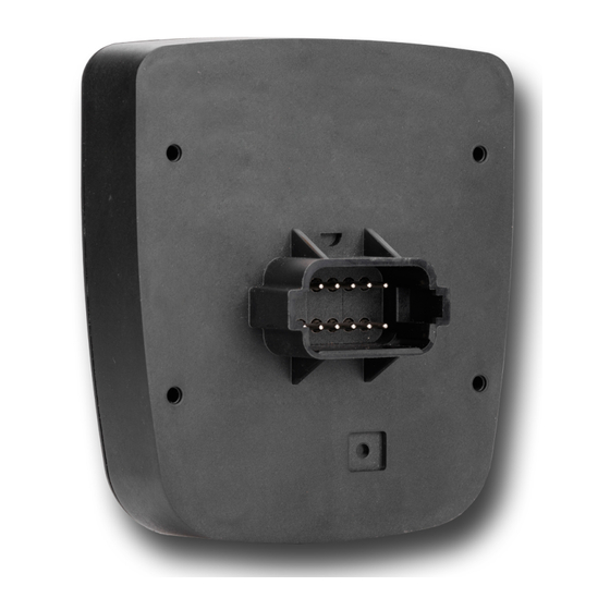
Page 17: Pin Assignment Of Deutsch Connector
CAN communication ■ ■ RS232 INFO Current consumption When the JCM-501-E01 is energized, the current consumption is temporarily higher. To ensure a reliable start-up of the device, provide at least 3 times the typical current required. CAN_2_H CAN_2_L USB_+5V CAN_1_H... -
Page 18: Programming
Format of numerical val- Notation Keyword Var, When, Task Commands BitClear(); Constant numerical values 100 0x100 0b100 Comment // This is a com- ment Further program processing // ... Tab. 17: JetSym sample programs JCM-501-E01 User Manual 18 / 55... -
Page 19: Canopen® Stx Api
CiA DS 4xx - These documents describe the behavior of a number of device classes in, what are known as, device profiles. 7.2.1 STX Functions Application STX functions are used in the communication between the JCM-501-E01 and ® other CANopen nodes. -
Page 20: Heartbeat Monitoring
Further information about this subject can be found in the topic "Heartbeat moni- ® toring" in the application-oriented manual "CANopen -STX-API" on our home- page. 7.2.3 CANopen® Object dictionary The operating system of the JCM-501-E01 supports the following objects: Index Object Type of Object name Data type (hex) -
Page 21: Sae J1939 Stx Api
For more information on SAE J1939 STX API refer to the application-oriented manual "SAE J1939 STX API" available for download on our homepage. 7.3.1 STX Functions Application STX functions are used in the communication between the JCM-501-E01 and other devices in a vehicle. The JCM-501-E01 supports the following STX functions: Features... -
Page 22: Serial Interface Rs-232
7.4 Serial interface RS-232 The JCM-501-E01 has a user-programmable RS-232 interface. 7.4.1 Operating principle The OS provides a receive buffer and a transmit buffer for the user-program- mable serial interface. These buffers can be used to adjust the transfer rate be- tween application program and serial interface. -
Page 23: Tab. 18 Elements Of The Serial Interface
The format of the received The erroneous character(s) is character does not match the (are) stored in the receive buf- set parameters. fer and error bit Framing error is set. The error counter is in- cremented. JCM-501-E01 User Manual 23 / 55... -
Page 24: Registers - Description
7.4.2 Registers - Description This chapter describes the registers associated with the user-programmable se- rial interface. These registers are used for the following tasks: ■ Parameterizing the interface ■ Sending characters ■ Receiving characters JCM-501-E01 User Manual 24 / 55... -
Page 25: Tab. 19 Register Numbers Of The Serial Interface
This register lets you set the number of stop bits per character. Property Description Values 1 stop bit 1.5 stop bits if MR 3 = 5 2 stop bits if MR 3 = 6, 7, 8 Value after reset Tab. 23: Stop bits JCM-501-E01 User Manual 25 / 55... -
Page 26: Tab. 24 Parity
Sending buffer filling level This register shows how many characters the sending buffer accommodates. There is space for 32,768 characters max. within the buffer. Property Description Values 0 ... 32,768 Tab. 27: Sending buffer filling level JCM-501-E01 User Manual 26 / 55... -
Page 27: Tab. 28 Receive Buffer, 8 Bits (Without Deleting The Character On Reading)
Second Bit 8 ... 15 Property Description Values 0 ... 65,535 Type of access Read Removes 2 characters from the buffer Takes effect if MR 14 > 1 Tab. 31: Receive buffer, 16-bit, little endian JCM-501-E01 User Manual 27 / 55... -
Page 28: Tab. 32 Receive Buffer; 16-Bit; Big Endian
Fourth Bit 0 ... 7 Property Description Values -2,147,483,648 ... 2,147,483,647 Type of access Read Removes 4 characters from the buffer Takes effect if MR 14 > 3 Tab. 34: Receive buffer; 32-bit; big endian JCM-501-E01 User Manual 28 / 55... -
Page 29: Programming
7.4.3.1 Activating the serial interface Module register MR 7 lets you activate the user-programmable serial interface. ü Configuring the in- The JCM-501-E01 and the device to communicate with have been wired ac- terface cording to the RS-232 interface standard. ►... -
Page 30: Sending Texts
Check the filling level of the receive buffer to make sure that it contains at least 2 or 4 characters. Read the values from Receive buffer registers MR 15 through MR 18. ð The characters are read from the receive buffer. JCM-501-E01 User Manual 30 / 55... -
Page 31: Real-Time Clock
The real-time clock has no automatic daylight savings time function. The JCM-501-E01 has a built-in battery with a service life of at least 10 years. 7.6 File system The file system lets you access files located on the internal flash disk or an USB flash drive. -
Page 32: Operating System Memory
By JetSym ■ By means of file commands from within the application program 7.7.4 Application program memory By default, the application program is uploaded from JetSym to the JCM-501-E01 and is stored there. Properties ■ Stored as file within the file system ■... -
Page 33: Usb Flash Drive
The following characters are not permitted in directory and file names: "/", "\", ":", "*", "?", "<", ">" and "|" ■ There is no user/access administration. Jetter AG cannot guarantee the proper functioning of all USB flash drives avail- able on the market. 7.7.7 Storing registers and variables Storing to a non-... -
Page 34: Automatic Copying Of Controller Data
This chapter describes the Autostart feature which lets you copy data within the JCM-501-E01. To this end, you can create a command file which is then stored along with the data to a USB flash drive. This command file is then automatically processed when the USB flash drive is inserted. -
Page 35: Executing The Autostart Function
7.8.2 Executing the AutoStart function During the boot phase in autostart mode, the device executes the commands in the command file. Executing the The operating system of the JCM-501-E01 processes the autostart function in the AutoStart function following steps: Step Description The file \USB\autostart.bat is loaded from the USB stick. -
Page 36: Example Of A Command File
Jetter AG Programming | 7 7.8.5 Example of a command file Task New functions are to be added to an installed JCM-501-E01. To this end, the fol- lowing modifications are required: ■ Operating system update ■ New application program ■... -
Page 37: Operating System Update
FS 12 1 FS 13 0 Automatically load- The JCM-501-E01 has a mechanism that allows a data file to be loaded automat- ing data file infor- ically before the application program starts. You must name the data file regis- mation ter.da and store it in the App folder. -
Page 38: Performing An Os Update Via Jeteasydownload
7.9.2 Performing an OS update via JetEasyDownload To update the operating system of a JCM-501-E01 use a Peak CAN dongle and the command line tool JetEasyDownload (version 1.00.0.15 or higher) by Jetter. Performing the up- JetEasyDownload -H100 -T127 -B5 -S8000 - Ljcm_ce0_X.XX.X.XX.os date ü... - Page 39 JCM-501-E01, the application program is loaded via the file system and exe- gram cuted. The application program is loaded by the OS of the JCM-501-E01 as follows: Level Description The operating system reads the file \App\start.ini from the internal flash disk.
-
Page 40: Registers - Overview
Jetter AG Registers - Overview | 8 8 Registers - Overview This register overview describes the registers of the JCM-501-E01 in summarized form. 8.1 Default address on the CANopen® bus Default address of the JCM-501-E01: Node ID: 127 (0x7F) 8.2 General overview - Registers... -
Page 41: Electronic Name Plate (Device As A Whole)
106100 Baud rate CAN 2 106101 Node ID CAN 2 8.8 Serial interface RS-232 Register ranges Description 103101 Protocol 103102 Baud rate 103103 Number of data bits per character 103104 Number of stop bits JCM-501-E01 User Manual 41 / 55... -
Page 42: Flash Memory
OS version (string) 108570 CPU type 108571 Number of CPUs 108573 Physical RAM 108574 Free physical RAM 108575 Memory utilization (in %) 108581 Screen width (in pixels) 108582 Screen height (in pixels) 108590 HID version JCM-501-E01 User Manual 42 / 55... -
Page 43: Usb Flash Drive
System command register 202980 Error history: Number of entries 202981 Error history: Index 202982 Error history: Entry 203100 ... 203107 32-bit overlaying Flags 0 ... 255 203108 ... 203123 16-bit overlaying Flags 0 ... 255 JCM-501-E01 User Manual 43 / 55... -
Page 44: Application Program
Manual triggering of a timer event (bit-coded) 210073 End of cyclic task (task ID) 210074 Command for cyclic tasks 210075 Number of timers 210076 Timer number (for R210077) 210077 Timer value in milliseconds 210100 ... 210199 Task state JCM-501-E01 User Manual 44 / 55... -
Page 45: File System/Data File Function
2224 ... 2239 203136 2112 ... 2127 203144 2240 ... 2255 203137 2128 ... 2143 203145 2256 ... 2271 203138 2144 ... 2159 203146 2272 ... 2287 203139 2160 ... 2175 203147 2288 ... 2303 JCM-501-E01 User Manual 45 / 55... -
Page 46: System Functions
For reasons of compatibility, the system functions are listed below. In JetSym STX, use the corresponding JetSym STX functions instead of system functions System functions Description Converting BCD to HEX Converting HEX to BCD Square root Sine Cosine Tangent Arc sine JCM-501-E01 User Manual 46 / 55... - Page 47 Ref Mode: String, VarType: DAWRITE_TYPE, First: Int, Last: int): Int; Function FileDARead(Const Ref FileName: String): Int; Function NetCopyListConfig(IPAddr: Int, IPPort: Int, Const Ref List: TNetCopyLinstL): Int; Function NetCopyListSend(Handle: int): Int; Function NetCopyListDelete(Handle: int): Int; JCM-501-E01 User Manual 47 / 55...
-
Page 48: Real-Time Clock
8.19 Real-time clock Direct access: 102910 Milliseconds 102911 Seconds 102912 Minutes 102913 hours 102914 Day of the week (0 = Sunday) 102915 102916 Month 102917 Year Buffer access: 102920 Milliseconds 102921 Seconds 102922 Minutes JCM-501-E01 User Manual 48 / 55... - Page 49 Jetter AG Registers - Overview | 8 Buffer access: 102923 hours 102924 Day of the week (0 = Sunday) 102925 102926 Month 102927 Year 102928 Read/write trigger JCM-501-E01 User Manual 49 / 55...
-
Page 50: Maintenance And Repairs
In case of damaged packaging inspect the device for any visible damage, and in- form your freight forwarder and the Jetter AG of the damage caused during ship- ment. If the device is damaged or has been dropped, it is strictly forbidden to use... -
Page 51: Service
To contact them, please call our technical hotline or use the contact form on our homepage: Technical hotline | Jetter - We automate your success. You are also welcome to send an e-mail to our technical hotline: hotline@jetter.de... -
Page 52: Spare Parts And Accessories
► Only use accessories recommended by Jetter AG. 11.1 Accessories INFO The accessories are not part of the scope of delivery. Apt accessories can be obtained from Jetter AG. Accessories Item number Connector set 10001264 consisting of Deutsch housing, crimp contacts (female) - Page 53 Space requirements for installation work (in mm) ..............Fig. 6 All dimensions of screw holes are in millimeters..............Fig. 7 Installing the strain relief......................Fig. 8 Deutsch connector, 12 pins..................... Fig. 9 Block Diagram - Serial Interface....................JCM-501-E01 User Manual 53 / 55...
- Page 54 Tab. 33 Receive buffer, 32-bit, little endian ..................Tab. 34 Receive buffer; 32-bit; big endian.................... Tab. 35 Error counter ........................... Tab. 36 Flash disk capacity ........................Tab. 37 Relevant directories......................... Tab. 38 Accessories ..........................JCM-501-E01 User Manual 54 / 55...
- Page 55 Jetter AG Graeterstrasse 2 71642 Ludwigsburg www.jetter.de E-mail info@jetter.de Phone +49 7141 2550-0 We automate your success.
Need help?
Do you have a question about the JCM-501-E01 and is the answer not in the manual?
Questions and answers