Rotax 125 MAX evo Repair Manual
Hide thumbs
Also See for 125 MAX evo:
- Repair manual (199 pages) ,
- Installation instructions and operators manual (112 pages) ,
- Installation instructions and operation manual (100 pages)
Table of Contents
Advertisement
Quick Links
See also:
Repair Manual
Advertisement
Table of Contents

Related Manuals for Rotax 125 MAX evo


Summary of Contents for Rotax 125 MAX evo
- Page 1 125 JUNIOR MAX evo 125 MINI MAX evo 125 MICRO MAX evo Part no. 298061 BRP-Rotax GmbH & Co KG | Rotaxstraße 1 | 4623 Gunskirchen, Austria | T: +43 7246 601 0 | F: +43 7246 637 0 www.rotax.com | www.rotax-kart.com...
- Page 2 Distribution or Service Center for ROTAX®-kart engines. Contents This Repair Manual contains instructions for all the necessary repair and maintenance work on the ROTAX®-Engine Type 125 MAX evo, 125 Junior MAX evo, 125 Mini MAX evo and 125 Micro MAX evo. Symbols used This Manual uses the following symbols to emphasize particular information.
-
Page 3: Edition - February 01 2018 /Rev
BRP-Rotax REPAIR MANUAL NOTES Notes Effectivity: 125 MAX evo, Junior MAX evo, Mini MAX evo, Micro MAX evo Page 2 Edition - February 01 2018 /Rev. 0... -
Page 4: Table Of Contents
Safety ..............................4 Safety notice ............................4 Instruction.............................5 Technical documentation........................6 Use for intended purpose ........................6 Technical data ............................7 Effectivity: 125 MAX evo, Junior MAX Chapter 1 evo, Mini MAX evo, Micro MAX evo Page 1 Edition - February 01 2018 /Rev. 0... - Page 5 BRP-Rotax REPAIR MANUAL Purpose This Repair Manual is based on information and the state-of-knowledge of BRP-Rotax of the product current at the date of issue. Documentation For additional information on engines, maintenance or parts, you can also contact your nearest authorized ROTAX®-Engine distributor.
-
Page 6: Abbreviations And Terms Used In This Manual
Research Octane Number Repair Manual Serial Number Service Instruction Service Letter part no. Part number Volt Effectivity: 125 MAX evo, Junior MAX Chapter 1 evo, Mini MAX evo, Micro MAX evo Page 3 Edition - February 01 2018 /Rev. 0... -
Page 7: Safety
Manual This Manual has been prepared as a guide to correctly service and maintain all ROTAX® Kart engines. This Manual uses technical terms which may be slightly different from the ones used in the Illustrated Parts Catalog. -
Page 8: Instruction
BRP-Rotax is null and void (see latest Warranty Conditions). Spare parts are available at the authorized ROTAX® Distribution- and Service Center. Any warranty by BRP-Rotax becomes null and void if spare parts and or accessories other than GEN- UINE ROTAX® spare parts and/or accessories are used (see latest Warranty Conditions). -
Page 9: Technical Documentation
The current edition of the Manual is shown at the bottom of the pages or on the front cover. Reference Any reference to a document refers to the latest edition issued by BRP-Rotax, if not stated otherwise. Illustrations The illustrations in this Manual are sketches and show a typical arrangement. They may not represent in full detail or the exact shape of the parts which have the same or similar function. -
Page 10: Technical Data
BRP-Rotax REPAIR MANUAL TECHNICAL DATA 125 MAX evo / 125 Junior MAX evo / 125 Mini Engine Type MAX evo / 125 Micro MAX evo Bore/stroke 54.00 mm / 54.5 mm Displacement 125.0 ccm Nominal power (max.) 22 kW at 11500 rpm... - Page 11 BRP-Rotax REPAIR MANUAL 125 MAX evo / 125 Junior MAX evo / 125 Mini Engine Type MAX evo / 125 Micro MAX evo SAE Engine oil 15W-40 Lubrication of the differential drive 50 ml (for plastic balance gears) Engine oil capacity...
- Page 12 Table of contents In this chapter the repair of engine ROTAX® 125 MAX evo (incl. Junior-, Mini-, Micro MAX evo) is described. Some overlapping maintenance instructions are treated as generally valid information at the beginning of this section.
- Page 13 We particularly emphasize that parts and accessories not supplied as genuine BRP-Rotax accessories parts are not verified for suitability by BRP-Rotax and thus are not authorized for use. In- stallation and/or use of such products may possibly change or negatively influence the constructive characteristics of the engine.
- Page 14 Including: • Suitable work environment to prevent contamination or damage to engine parts or modules. • Appropriate tools and fixtures as outlined in the ROTAX® Repair Manual. • Reasonable maintenance practices are utilized. Information Maintenance organizations and individuals are encouraged to contact BRP-Rotax through its worldwide distribution network for information and guidance on any of the tasks out- lined herein.
- Page 15 If during diassembling/reassembling the removal of a safety item (e.g. safety wiring, self-locking fastener, etc.) should be necessary, it must be always replaced by a new one. Chapter 2 Effectivity: 125 MAX evo, Junior MAX evo, Mini MAX evo, Micro MAX evo Page 4 Edition - February 01 2018 /Rev. 0...
- Page 16 Before re-assembly check components whether parts are missing. Only use adhesives, lubricants, cleaning agents and solvents indicated in the maintenance instructions. If not respected, damage may be the consequence and no warranty claim. Effectivity: 125 MAX evo, Junior MAX Chapter 2 evo, Mini MAX evo, Micro MAX evo Page 5 Edition - February 01 2018 /Rev.
- Page 17 CONSUMABLE MATERIALS General note ATTENTION Use only the specified or technically equivalent materials from BRP-Rotax for all maintenance work. When handling chemicals, comply with all the customary regula- tions and specifications of the producer, including the expiry date and instruction.
- Page 18 “Clenvex 2000“. It is a solvent-cold cleaner, free of halogen, on the basis of selected fuel fractions with tensides and is biologically disposable. Never use caustic or corrosive cleaning. Figure 2.1 Effectivity: 125 MAX evo, Junior MAX Chapter 2 evo, Mini MAX evo, Micro MAX evo Page 7...
-
Page 19: Special Tools
BRP-Rotax REPAIR MANUAL SPECIAL TOOLS Figure 2.2 Chapter 2 Effectivity: 125 MAX evo, Junior MAX evo, Mini MAX evo, Micro MAX evo Page 8 Edition - February 01 2018 /Rev. 0... - Page 20 For authorised distributors only. 276110 ROTAX SEAL CALLIPER For authorised distributors only. 297240 ENGINE IDENTITY CARD Effectivity: 125 MAX evo, Junior MAX Chapter 2 evo, Mini MAX evo, Micro MAX evo Page 9 Edition - February 01 2018 /Rev. 0...
- Page 21 Chapter 2 Effectivity: 125 MAX evo, Junior MAX evo, Mini MAX evo, Micro MAX evo Page 10 Edition - February 01 2018 /Rev. 0...
- Page 22 10) Engine inspection Engine inspection by authorized serv- Every 50 hours ice center, replace defective parts. of operation Effectivity: 125 MAX evo, Junior MAX Chapter 2 evo, Mini MAX evo, Micro MAX evo Page 11 Edition - February 01 2018 /Rev. 0...
- Page 23 BRP-Rotax REPAIR MANUAL NOTES Notes Effectivity: 125 MAX evo, Junior MAX evo, Mini MAX evo, Micro MAX evo Page 12 Edition - February 01 2018 /Rev. 0...
- Page 24 Removal of the engine from kart chassis ....................8 Positioning the engine on the trestle mounting plate .................9 Contents This chapter describes the disassembly and assembly of the ROTAX® 125 MAX evo (incl. Junior-, Mini-, Micro MAX evo) engine. Effectivity: 125 MAX evo, Junior MAX...
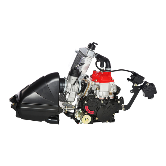
- Page 25 Figure 3.1: Engine components Engine Carburetor Exhaust system Intake silencer Fuel pump Radiator Battery mounting + ECU Chapter 3 Effectivity: 125 MAX evo, Junior MAX evo, Mini MAX evo, Micro MAX evo Page 2 Edition - February 01 2018 /Rev. 0...
- Page 26 1. Remove the Allen screw with rounded flange head M6x20 (3) with O-ring 5x2 (2). 2. Remove the battery cover (1). 3. Disconnect the negative battery terminal (5). Effectivity: 125 MAX evo, Junior MAX Chapter 3 evo, Mini MAX evo, Micro MAX evo Page 3 Edition - February 01 2018 /Rev.
- Page 27 8. Disconnect the connector (9) for the pick up sensor (3) 9. Disconnect the connector (10) for the starter (4). Chapter 3 Effectivity: 125 MAX evo, Junior MAX evo, Mini MAX evo, Micro MAX evo Page 4 Edition - February 01 2018 /Rev. 0...
- Page 28 Connector ignition coil Solenoid valve Solenoid connector Allen screw M6x25 CPS connector Starter connector Cable tie ______________________________________________________ Effectivity: 125 MAX evo, Junior MAX Chapter 3 evo, Mini MAX evo, Micro MAX evo Page 5 Edition - February 01 2018 /Rev. 0...
- Page 29 Proceeds follows to dismantle the radiator with cap assy.: Step Procedure Removal of radiator with cap assy. See Chapter 8. Chapter 3 Effectivity: 125 MAX evo, Junior MAX evo, Mini MAX evo, Micro MAX evo Page 6 Edition - February 01 2018 /Rev. 0...
- Page 30 1. Pull off fuel line (2) from the fuel pump (1). Figure 3.4: Fuel components Fuel pump Fuel line Impulse hose ______________________________________________________ Effectivity: 125 MAX evo, Junior MAX Chapter 3 evo, Mini MAX evo, Micro MAX evo Page 7 Edition - February 01 2018 /Rev. 0...
- Page 31 • Cylinder with combustion chamber insert and cylinder head cover • Exhaust valve • Reed valve • Piston • Starter • Oil Service Chapter 3 Effectivity: 125 MAX evo, Junior MAX evo, Mini MAX evo, Micro MAX evo Page 8 Edition - February 01 2018 /Rev. 0...
- Page 32 Fixing plate for engine Engine Instructions Proceed as follows to position the engine on the trestle mounting plate: Effectivity: 125 MAX evo, Junior MAX Chapter 3 evo, Mini MAX evo, Micro MAX evo Page 9 Edition - February 01 2018 /Rev. 0...
- Page 33 2. Unscrew the base plate from the engine, position the engine on the trestle mounting plate, and fix it securely with the 4 fixing screws. Chapter 3 Effectivity: 125 MAX evo, Junior MAX evo, Mini MAX evo, Micro MAX evo Page 10...
-
Page 34: Chapter: Chapter
Installation of spark plug ........................33 Contents This chapter describes the disassembly and assembly of the cylinder components of the ROTAX® 125 MAX evo (incl. Junior-, Mini-, Micro MAX evo) engine. The description is divided into sections. Effectivity: 125 MAX evo, Junior MAX... - Page 35 Figure 4.1: MAX evo engine shown in figure Cylinder Cylinder head cover Intake socket E-Rave cover Exhaust socket assy. Chapter 4 Effectivity: 125 MAX evo, Junior MAX evo, Mini MAX evo, Micro MAX evo Page 2 Edition - February 01 2018 /Rev. 0...
- Page 36 The following special tools and equipment are required: Part no. Description Field of application 676110 Socket set Cylinder Effectivity: 125 MAX evo, Junior MAX Chapter 4 evo, Mini MAX evo, Micro MAX evo Page 3 Edition - February 01 2018 /Rev. 0...
- Page 37 1. Remove the cylinder head cover (1) by removing the 3 Allen screws (M6x25) (3) and 1 Allen screw M6x16 (4) from the cylinder. 2. Remove the cylinder head together with the gasket. Chapter 4 Effectivity: 125 MAX evo, Junior MAX evo, Mini MAX evo, Micro MAX evo Page 4 Edition - February 01 2018 /Rev. 0...
- Page 38 M4x8 (6) on the thermostat retaining bracket (5). 2. Remove the compression spring (4). 3. Remove the thermostat (2) from the thermostat holder (3). Effectivity: 125 MAX evo, Junior MAX Chapter 4 evo, Mini MAX evo, Micro MAX evo Page 5 Edition - February 01 2018 /Rev.
- Page 39 (5) crosswise. 2. Lift away the combustion chamber insert with lower (2) and upper O-rings (3). Chapter 4 Effectivity: 125 MAX evo, Junior MAX evo, Mini MAX evo, Micro MAX evo Page 6 Edition - February 01 2018 /Rev. 0...
- Page 40 2. Remove the gasket (4). Figure 4.6: Exhaust socket Exhaust gasket Exhaust socket Allen screw M8x20 Gasket Cylinder ______________________________________________________ Effectivity: 125 MAX evo, Junior MAX Chapter 4 evo, Mini MAX evo, Micro MAX evo Page 7 Edition - February 01 2018 /Rev. 0...
- Page 41 Engines/124-Rotax-E-RAVE Chapter 4 Effectivity: 125 MAX evo, Junior MAX evo, Mini MAX evo, Micro MAX evo Page 8 Edition - February 01 2018 /Rev. 0...
- Page 42 Valve rod housing assy. Spring washer B6 Allen screw M6x25 Gasket Exhaust valve O-ring 6x2.5 RED Stud M6x52.5 ______________________________________________________ Effectivity: 125 MAX evo, Junior MAX Chapter 4 evo, Mini MAX evo, Micro MAX evo Page 9 Edition - February 01 2018 /Rev. 0...
- Page 43 2. Press the piston pin (4) out of the piston with the point of the special tool (3). Figure 4.9: Piston Circlip puller Circlip Special tool part no. 676035 Piston pin Chapter 4 Effectivity: 125 MAX evo, Junior MAX evo, Mini MAX evo, Micro MAX evo Page 10 Edition - February 01 2018 /Rev. 0...
- Page 44 7. Inspect the impulse bore (4). Figure 4.10: Cylinder Exhaust valve port Water duct Groove for O-ring Impulse bore ______________________________________________________ Effectivity: 125 MAX evo, Junior MAX Chapter 4 evo, Mini MAX evo, Micro MAX evo Page 11 Edition - February 01 2018 /Rev. 0...
- Page 45 8. Check the piston ring locking pin for wear. Figure 4.11: Piston and piston ring Feeler gauge Piston ring ______________________________________________________ Chapter 4 Effectivity: 125 MAX evo, Junior MAX evo, Mini MAX evo, Micro MAX evo Page 12 Edition - February 01 2018 /Rev. 0...
- Page 46 The piston clearance of a new piston/cylinder pairing should be 0.04 - 0.05 mm. Figure 1.12: Piston diameter Micrometer ______________________________________________________ Effectivity: 125 MAX evo, Junior MAX Chapter 4 evo, Mini MAX evo, Micro MAX evo Page 13 Edition - February 01 2018 /Rev. 0...
- Page 47 “f” 53.98 +0.005 / -0.025 mm 53.955 53.985 “f” 53.99 +0.005 / -0.025 mm 53.965 53.995 Chapter 4 Effectivity: 125 MAX evo, Junior MAX evo, Mini MAX evo, Micro MAX evo Page 14 Edition - February 01 2018 /Rev. 0...
- Page 48 Direction of circlips is up or downside direction. Figure 1.13: Piston pin, circlip Piston pin Needle cage Circlip ______________________________________________________ Effectivity: 125 MAX evo, Junior MAX Chapter 4 evo, Mini MAX evo, Micro MAX evo Page 15 Edition - February 01 2018 /Rev. 0...
- Page 49 Pay attention to the electrode gap, mentioned in the technical regulation! Bending the electrode can cause damage or misfire. Figure 1.14: Spark plug Spark plug Electrode ______________________________________________________ Chapter 4 Effectivity: 125 MAX evo, Junior MAX evo, Mini MAX evo, Micro MAX evo Page 16 Edition - February 01 2018 /Rev. 0...
- Page 50 2. Inspect combustion chamber insert for cracks (visual inspection). 3. Make sure that spark plug thread (3) is in good condition. 4. Inspect sealing surfaces for flatness and damage. Effectivity: 125 MAX evo, Junior MAX Chapter 4 evo, Mini MAX evo, Micro MAX evo Page 17 Edition - February 01 2018 /Rev.
- Page 51 2. Inspect exhaust gasket (2) for wear and replace if applicable. Figure 4.17: Exhaust socket Exhaust socket (ball) Exhaust gasket ______________________________________________________ Chapter 4 Effectivity: 125 MAX evo, Junior MAX evo, Mini MAX evo, Micro MAX evo Page 18 Edition - February 01 2018 /Rev. 0...
- Page 52 Figure 4.18: Carburetor port and valve guide Reed valve assy. Reed petal Oval head screw M3x6 Intake socket ______________________________________________________ Effectivity: 125 MAX evo, Junior MAX Chapter 4 evo, Mini MAX evo, Micro MAX evo Page 19 Edition - February 01 2018 /Rev. 0...
- Page 53 Figure 4.19: Exhaust valve O-ring RED Exhaust valve Valve rod housing Oil seal Valve piston Bellow Valve cover ______________________________________________________ Chapter 4 Effectivity: 125 MAX evo, Junior MAX evo, Mini MAX evo, Micro MAX evo Page 20 Edition - February 01 2018 /Rev. 0...
- Page 54 3. Make sure the bolt is screwed in completely. Tightening torque 10 Nm (90 in.lb). Figure 4.20: Exhaust valve Exhaust valve Stud M6x52.5 O-ring 6x2.5 RED ______________________________________________________ Effectivity: 125 MAX evo, Junior MAX Chapter 4 evo, Mini MAX evo, Micro MAX evo Page 21 Edition - February 01 2018 /Rev. 0...
- Page 55 1. Degrease the valve rod housing (1), bellows (2) and exhaust valve piston (3). 2. Pull the small hose spring (4) over the bellows. Chapter 4 Effectivity: 125 MAX evo, Junior MAX evo, Mini MAX evo, Micro MAX evo Page 22...
- Page 56 Hose spring 134-3.0-0.65 Compression spring 48.5/0.8 mm Valve cover TAPTITE screw M5x25 O-ring 15.9-2.3 Adjustment screw ______________________________________________________ Effectivity: 125 MAX evo, Junior MAX Chapter 4 evo, Mini MAX evo, Micro MAX evo Page 23 Edition - February 01 2018 /Rev. 0...
- Page 57 N N O O T T E E The installation tool centers itself in the piston pin. Chapter 4 Effectivity: 125 MAX evo, Junior MAX evo, Mini MAX evo, Micro MAX evo Page 24 Edition - February 01 2018 /Rev. 0...
- Page 58 The following special tools and equipment are required: Part no. Description Field of application 897651 LOCTITE 243 Stud bolts Effectivity: 125 MAX evo, Junior MAX Chapter 4 evo, Mini MAX evo, Micro MAX evo Page 25 Edition - February 01 2018 /Rev. 0...
- Page 59 ______________________________________________________ INSTALLATION OF THE EXHAUST SOCKET Special tools The following special tools and equipment are required: Chapter 4 Effectivity: 125 MAX evo, Junior MAX evo, Mini MAX evo, Micro MAX evo Page 26 Edition - February 01 2018 /Rev. 0...
- Page 60 Screw locking Instructions Figure: Carburetor flange and reed valve Proceed as follows to install the exhaust socket: Effectivity: 125 MAX evo, Junior MAX Chapter 4 evo, Mini MAX evo, Micro MAX evo Page 27 Edition - February 01 2018 /Rev. 0...
- Page 61 Carburetor flange Gasket Allen screw M6x25, with hole for sealing Support bracket the engine Allen screw M6x25, Chapter 4 Effectivity: 125 MAX evo, Junior MAX evo, Mini MAX evo, Micro MAX evo Page 28 Edition - February 01 2018 /Rev. 0...
- Page 62 Screw locking Preparation The following preparation is required before installation: • Installation of the coolant thermostat: Effectivity: 125 MAX evo, Junior MAX Chapter 4 evo, Mini MAX evo, Micro MAX evo Page 29 Edition - February 01 2018 /Rev. 0...
- Page 63 5. Tighten the cylinder head cover (3) crosswise with 4 Allen screws M6x25 (4). Tightening tor- que 10 Nm (90 in.lb). Chapter 4 Effectivity: 125 MAX evo, Junior MAX evo, Mini MAX evo, Micro MAX evo Page 30 Edition - February 01 2018 /Rev. 0...
- Page 64 Solder Instructions Figure: Squish gap measurement. 1. Rotate crankshaft by hand until the piston is approx. 5 mm below TDC. Effectivity: 125 MAX evo, Junior MAX Chapter 4 evo, Mini MAX evo, Micro MAX evo Page 31 Edition - February 01 2018 /Rev. 0...
- Page 65 “Installation of the cylinder”. Keep in mind that the gasket will settle and reduce the squish over time. Chapter 4 Effectivity: 125 MAX evo, Junior MAX evo, Mini MAX evo, Micro MAX evo Page 32 Edition - February 01 2018 /Rev. 0...
- Page 66 Proceed as follows to install the spark plug: 1. Screw in spark plug hand-tight and use tightening torque to tighten it with 27 Nm (20 ft.lb). Effectivity: 125 MAX evo, Junior MAX Chapter 4 evo, Mini MAX evo, Micro MAX evo Page 33 Edition - February 01 2018 /Rev.
- Page 67 BRP-Rotax REPAIR MANUAL NOTES Notes Effectivity: 125 MAX evo, Junior MAX evo, Mini MAX evo, Micro MAX evo Page 34 Edition - February 01 2018 /Rev. 0...
- Page 68 Installation of crankcase assy.......................37 Installation of balance and water-pump shaft drive .................37 Contents This chapter describes the disassembly and assembly of the crankcase of the ROTAX® 125 MAX evo (incl. Junior-, Mini-, Micro MAX evo) engine. Effectivity: 125 MAX evo, Junior MAX...
- Page 69 BRP-Rotax REPAIR MANUAL SYSTEM DESCRIPTION Overview Figure 5.1: Position on the engine Chapter 5 Effectivity: 125 MAX evo, Junior MAX evo, Mini MAX evo, Micro MAX evo Page 2 Edition - February 01 2018 /Rev. 0...
- Page 70 Water pump pinion 16 T Needle pin 4x15.8 Thrust washer 10.1/17/1 Balance gear (crankshaft) Balance gear (balance shaft) Effectivity: 125 MAX evo, Junior MAX Chapter 5 evo, Mini MAX evo, Micro MAX evo Page 3 Edition - February 01 2018 /Rev. 0...
- Page 71 Oil seal A 10x26x7 Oil seal AS 28x38x7 Closure cap for impulse joint Air vent screw M18x1.5 Chapter 5 Effectivity: 125 MAX evo, Junior MAX evo, Mini MAX evo, Micro MAX evo Page 4 Edition - February 01 2018 /Rev. 0...
- Page 72 1. Remove the Allen screw (3) with gasket (2) from the crankcase and gearbox case. 2. Drain the oil into a suitable vessel and dispose of it in the proper manner. Effectivity: 125 MAX evo, Junior MAX Chapter 5 evo, Mini MAX evo, Micro MAX evo Page 5 Edition - February 01 2018 /Rev.
- Page 73 1. Unscrew and remove Allen screws (1). 2. Remove gear cover (3) with gasket (4). Chapter 5 Effectivity: 125 MAX evo, Junior MAX evo, Mini MAX evo, Micro MAX evo Page 6 Edition - February 01 2018 /Rev. 0...
- Page 74 7. Heat balance gear (8,7) evenly with hot air if they do not move freely and remove them from crankshaft or balance shaft. 8. Remove O-ring (9) from the crankshaft. Effectivity: 125 MAX evo, Junior MAX Chapter 5 evo, Mini MAX evo, Micro MAX evo Page 7 Edition - February 01 2018 /Rev.
- Page 75 Retaining ring with lug 20x1.2 Water pump gear 19 T Balance gear 50 T Balance gear 50T O-ring 18x3.5 ______________________________________________________ Chapter 5 Effectivity: 125 MAX evo, Junior MAX evo, Mini MAX evo, Micro MAX evo Page 8 Edition - February 01 2018 /Rev. 0...
- Page 76 3. Screw Allen screws (1,2) evenly into the extraction thread and press the case halves evenly apart. Figure 5.6: Crankcase Allen screws ______________________________________________________ Effectivity: 125 MAX evo, Junior MAX Chapter 5 evo, Mini MAX evo, Micro MAX evo Page 9 Edition - February 01 2018 /Rev. 0...
- Page 77 7. Gently tap the crankshaft (1) with the plastic hammer (3) to remove the crankshaft from the case half (2). Chapter 5 Effectivity: 125 MAX evo, Junior MAX evo, Mini MAX evo, Micro MAX evo Page 10 Edition - February 01 2018 /Rev. 0...
- Page 78 5. Remove countersunk screw (7) and thrust washer (8). 6. Heat the two halves of the case to approx. 150 °C in the convection oven until the bearing can be tapped gently out. Effectivity: 125 MAX evo, Junior MAX Chapter 5 evo, Mini MAX evo, Micro MAX evo Page 11 Edition - February 01 2018 /Rev.
- Page 79 (2) of the crankshaft and the ball bearing (3) from the case. 8. Invert the case half and remove the needle bushing (5) with the installation tool (4). Chapter 5 Effectivity: 125 MAX evo, Junior MAX evo, Mini MAX evo, Micro MAX evo Page 12...
- Page 80 This removes the ball bearing (4,5) from the crankshaft and the balance shaft. 10. Allow both crankcase halves to cool to room temperature (20 °C) (274 °F). Effectivity: 125 MAX evo, Junior MAX Chapter 5 evo, Mini MAX evo, Micro MAX evo Page 13 Edition - February 01 2018 /Rev.
- Page 81 Locating pin 8 small M6x40 Pin 8x12 Crankcase assy. Ball bearing 6206 Ball bearing 6005 ______________________________________________________ Chapter 5 Effectivity: 125 MAX evo, Junior MAX evo, Mini MAX evo, Micro MAX evo Page 14 Edition - February 01 2018 /Rev. 0...
- Page 82 Field of application n.a. Press Crankshaft disassembling n.a. Dial gauge Crankshaft measurements 276051 crankshaft repair jig Crankshaft Effectivity: 125 MAX evo, Junior MAX Chapter 5 evo, Mini MAX evo, Micro MAX evo Page 15 Edition - February 01 2018 /Rev. 0...
- Page 83 N N O O T T E E Con rod parts are not part of the crankshaft repair jig (part no. 276051). The crankshaft repair kit (con rod) is available at your ROTAX® Dealer. Chapter 5 Effectivity: 125 MAX evo, Junior MAX...
- Page 84 (4). 3. Position the thrust pin (5) on the connecting rod pin and press the crankshaft apart. Effectivity: 125 MAX evo, Junior MAX Chapter 5...
- Page 85 Crankshaft half Thrust pin Con rod pin Con rod Drive side of the crankshaft half Press ______________________________________________________ Chapter 5 Effectivity: 125 MAX evo, Junior MAX evo, Mini MAX evo, Micro MAX evo Page 18 Edition - February 01 2018 /Rev. 0...
- Page 86 N N O O T T E E If one of the wear limits CS03, CS04 or CS05 is reached, BRP-Rotax recom- mends use of the applicable repair kit. See also Chapter 5 Figure: Con rod parts. N N O O T T E E If the maximum approved stroke (CS06) of the crankshaft is exceeded, the crank- shaft must be realigned.
- Page 87 CS05 0.05 mm 0.08 mm Stroke of crankshaft CS06 0.0 mm - 0.015 mm 0.03 mm Chapter 5 Effectivity: 125 MAX evo, Junior MAX evo, Mini MAX evo, Micro MAX evo Page 20 Edition - February 01 2018 /Rev. 0...
- Page 88 Vise Crowbar 3. The crankshaft can be aligned to the external diameter of the crankshaft webs with target strokes of an aluminum hammer. Effectivity: 125 MAX evo, Junior MAX Chapter 5 evo, Mini MAX evo, Micro MAX evo Page 21...
- Page 89 2. Insert the new con rod pin (5) into the crankshaft bore. 3. Place the sleeve (6) over it. Chapter 5 Effectivity: 125 MAX evo, Junior MAX evo, Mini MAX evo, Micro MAX evo Page 22 Edition - February 01 2018 /Rev. 0...
- Page 90 Instructions Figure: Crankshaft assembly. 6. Slide the gearbox-end crankshaft half (1) into the bottom section of the tool (2). Effectivity: 125 MAX evo, Junior MAX Chapter 5 evo, Mini MAX evo, Micro MAX evo Page 23 Edition - February 01 2018 /Rev. 0...
- Page 91 11. Position the thrust ring (4) on the top section of the repair jig and press the two crankshaft halves together (until the crankshaft pin is aligned with the crankshaft web). Chapter 5 Effectivity: 125 MAX evo, Junior MAX evo, Mini MAX evo, Micro MAX evo Page 24...
- Page 92 Press stamp Bottom section of the repair jig Top section of the repair jig Thrust ring ______________________________________________________ Effectivity: 125 MAX evo, Junior MAX Chapter 5 evo, Mini MAX evo, Micro MAX evo Page 25 Edition - February 01 2018 /Rev. 0...
- Page 93 Figure 5.21: Water pump drive Water pump gear 19 T Idle gear 28/13 T Water pump pinion 16 T ______________________________________________________ Chapter 5 Effectivity: 125 MAX evo, Junior MAX evo, Mini MAX evo, Micro MAX evo Page 26 Edition - February 01 2018 /Rev. 0...
- Page 94 N N O O T T E E The balance gears (1) and the O-ring (2) should be replaced at least every 50 op- erating hours. Effectivity: 125 MAX evo, Junior MAX Chapter 5 evo, Mini MAX evo, Micro MAX evo Page 27 Edition - February 01 2018 /Rev.
- Page 95 14.96 mm - 14.94 mm 14.99 mm Clutch bearing seat BS11 24.97 mm - 24.94 mm 24.99 mm Chapter 5 Effectivity: 125 MAX evo, Junior MAX evo, Mini MAX evo, Micro MAX evo Page 28 Edition - February 01 2018 /Rev. 0...
- Page 96 5. Check that lubrication holes (4) are open and clean with compressed air as required. Figure 5.25: Crankcase Sealing surfaces Case halves Main bearing lubrication hole Thread ______________________________________________________ Effectivity: 125 MAX evo, Junior MAX Chapter 5 evo, Mini MAX evo, Micro MAX evo Page 29 Edition - February 01 2018 /Rev. 0...
- Page 97 The oil seal for shaft can also be installed from outside to inside if the crankshaft is installed. Chapter 5 Effectivity: 125 MAX evo, Junior MAX evo, Mini MAX evo, Micro MAX evo Page 30 Edition - February 01 2018 /Rev. 0...
- Page 98 Figure 5.27: Ball bearing Ball bearing 6206 Ball bearing 6302 ______________________________________________________ Effectivity: 125 MAX evo, Junior MAX Chapter 5 evo, Mini MAX evo, Micro MAX evo Page 31 Edition - February 01 2018 /Rev. 0...
- Page 99 5. Press in the oil seal (4) to the limit stop with the insertion sleeve (5) (part no. 676010) so the open end of the oil seal for shaft is directed to the balance drive. Chapter 5 Effectivity: 125 MAX evo, Junior MAX evo, Mini MAX evo, Micro MAX evo Page 32...
- Page 100 11. Press in the second oil seal for shaft to the limit stop with the installation tool (8) (part no. 676021) so the open end of the oil seal (4) for shaft is visible. 12. Allow the crankcase halves to cool in this position. Effectivity: 125 MAX evo, Junior MAX Chapter 5 evo, Mini MAX evo, Micro MAX evo Page 33 Edition - February 01 2018 /Rev.
- Page 101 Figure 5.30: Insertion jig Ball bearing 6206 Oil seal 10x26x7 Insertion jig Oil seal 10x26x7 (open end) ______________________________________________________ Chapter 5 Effectivity: 125 MAX evo, Junior MAX evo, Mini MAX evo, Micro MAX evo Page 34 Edition - February 01 2018 /Rev. 0...
- Page 102 Figure 5.31: Crankshaft, Balance shaft, Water pump shaft Crankshaft assy. Balance shaft Water pump shaft Gasket ______________________________________________________ Effectivity: 125 MAX evo, Junior MAX Chapter 5 evo, Mini MAX evo, Micro MAX evo Page 35 Edition - February 01 2018 /Rev. 0...
- Page 103 5. Cut off the protruding section of the crankcase gasket with a sharp knife at the cylinder base surface. Chapter 5 Effectivity: 125 MAX evo, Junior MAX evo, Mini MAX evo, Micro MAX evo Page 36 Edition - February 01 2018 /Rev. 0...
- Page 104 4. Slide the balance shaft gear (5) with hub collar inwards on the balance shaft until the mark- ings (6) on the balance shaft and the balance gear match. Effectivity: 125 MAX evo, Junior MAX Chapter 5 evo, Mini MAX evo, Micro MAX evo Page 37 Edition - February 01 2018 /Rev.
- Page 105 8. Check the seating of the needle pin (4) in the cutout in the water pump pinion. 9. Install the idle gear (7) on the cylindrical pin in the case. Chapter 5 Effectivity: 125 MAX evo, Junior MAX evo, Mini MAX evo, Micro MAX evo Page 38...
- Page 106 M6x30 (5). Tightening torque 10 Nm (90 in. lb). N N O O T T E E Use sealing ring A6x10 to seal the oil drainage plug and oil level plug. Effectivity: 125 MAX evo, Junior MAX Chapter 5 evo, Mini MAX evo, Micro MAX evo Page 39 Edition - February 01 2018 /Rev.
- Page 107 Figure 5.35 Gasket Gearbox cover Sealing ring A 6x10 Allen screw M6x25 Allen screw M6x30 ______________________________________________________ Chapter 5 Effectivity: 125 MAX evo, Junior MAX evo, Mini MAX evo, Micro MAX evo Page 40 Edition - February 01 2018 /Rev. 0...
- Page 108 Contents This chapter describes the removal and installation of the carburetor and intake silencer assembly for the ROTAX® 125 MAX evo (incl. Junior-, Mini-, Micro MAX evo) engine. The description is divided into subsections. Effectivity: 125 MAX evo, Junior MAX...
- Page 109 BRP-Rotax REPAIR MANUAL SYSTEM DESCRIPTION Overview Position on engine Figure 6.1: Position on engine, TYPICAL (Figure shows 125 MAX evo engine) Intake silencer Carburetor Fuel pump Chapter 6 Effectivity: 125 MAX evo, Junior MAX evo, Mini MAX evo, Micro MAX evo Page 2 Edition - February 01 2018 /Rev.
- Page 110 3. Loosen the hose clamp (7). 4. Loosen 3 Allen screws (5) and remove the carburetor (3) along with the intake silencer (8), support bracket (6) and fuel pump (4). Effectivity: 125 MAX evo, Junior MAX Chapter 6 evo, Mini MAX evo, Micro MAX evo Page 3 Edition - February 01 2018 /Rev.
- Page 111 1. Loosen 2 Allen screws M6 with washers fixed by lock nuts. 2. Remove the fuel pump (1) from the support bracket (2). Chapter 6 Effectivity: 125 MAX evo, Junior MAX evo, Mini MAX evo, Micro MAX evo Page 4...
- Page 112 1. Disassembly of the carburetor to the parts shown in Figure: Carburetor and clean them with fuel. Effectivity: 125 MAX evo, Junior MAX Chapter 6 evo, Mini MAX evo, Micro MAX evo Page 5 Edition - February 01 2018 /Rev. 0...
- Page 113 BRP-Rotax REPAIR MANUAL Figure 6.4: Carburetor Chapter 6 Effectivity: 125 MAX evo, Junior MAX evo, Mini MAX evo, Micro MAX evo Page 6 Edition - February 01 2018 /Rev. 0...
- Page 114 Filter element support/holder Intake silencer tube Support bracket Filter element Washer 6.4 Allen screw M6x20 Nut M6 ______________________________________________________ Effectivity: 125 MAX evo, Junior MAX Chapter 6 evo, Mini MAX evo, Micro MAX evo Page 7 Edition - February 01 2018 /Rev. 0...
- Page 115 Main jet Main jet cup Needle valve 150 (standard) 200 Clip (optional) Jet needle K 57 ______________________________________________________ Chapter 6 Effectivity: 125 MAX evo, Junior MAX evo, Mini MAX evo, Micro MAX evo Page 8 Edition - February 01 2018 /Rev. 0...
- Page 116 3. Clean the filter element (5) with filter cleaner and oil it afterwards slightly with air filter oil. 4. Inspect the filter element (5) and filter element holders (4) for cracks. Effectivity: 125 MAX evo, Junior MAX Chapter 6 evo, Mini MAX evo, Micro MAX evo Page 9 Edition - February 01 2018 /Rev.
- Page 117 Filter element support/holder Intake silencer tube Support bracket Filter element Washer 6.4 Allen screw M6x20 Nut M6 ______________________________________________________ Chapter 6 Effectivity: 125 MAX evo, Junior MAX evo, Mini MAX evo, Micro MAX evo Page 10 Edition - February 01 2018 /Rev. 0...
- Page 118 ASSEMBLY OF CARBURETOR Instruction N N O O T T E E Use ROTAX® gasket set, part no. 293834. 1. Assemble the components in the opposite succession as you disassembled them. See also Chapter 6) section: Disassembly of the carburetor.
- Page 119 1. Assemble the components in the opposite succession as you disassembled them. See also Chapter 6. section: Disassembly of the intake silencer. Chapter 6 Effectivity: 125 MAX evo, Junior MAX evo, Mini MAX evo, Micro MAX evo Page 12 Edition - February 01 2018 /Rev. 0...
- Page 120 Figure 6.10: Fuel pump Fuel pump Support bracket Lock nut M6 Washer 6.4 Allen screw M6x20 Allen screw M6x25 Effectivity: 125 MAX evo, Junior MAX Chapter 6 evo, Mini MAX evo, Micro MAX evo Page 13 Edition - February 01 2018 /Rev. 0...
- Page 121 Allen screw M6x25 Washer 6.4 Impulse pipe Fuel feed tube/line Bowden cable (loosely, not mounted in fig.) ______________________________________________________ Chapter 6 Effectivity: 125 MAX evo, Junior MAX evo, Mini MAX evo, Micro MAX evo Page 14 Edition - February 01 2018 /Rev. 0...
- Page 122 Contents This chapter describes the disassembly and assembly of the centrifugal clutch and the primary and balance drive for the ROTAX® 125 MAX evo (incl. Junior-, Mini-, Micro MAX evo) engine. The description is broken down into subsections. Effectivity: 125 MAX evo, Junior MAX...
- Page 123 Position on engine Figure 7.1: Clutch and starter gear assy. Starter gear assy. Clutch drum Sprocket ______________________________________________________ Chapter 7 Effectivity: 125 MAX evo, Junior MAX evo, Mini MAX evo, Micro MAX evo Page 2 Edition - February 01 2018 /Rev. 0...
- Page 124 Starter reduction gear assy. Allen screw M6x12 Thrust washer 8.5 Electric starter Starter support Allen screw M6x35 Effectivity: 125 MAX evo, Junior MAX Chapter 7 evo, Mini MAX evo, Micro MAX evo Page 3 Edition - February 01 2018 /Rev. 0...
- Page 125 Figure 7.3: Electric starter Starter support Electric starter Allen screw M6x35 Allen screw M6x30 Chapter 7 Effectivity: 125 MAX evo, Junior MAX evo, Mini MAX evo, Micro MAX evo Page 4 Edition - February 01 2018 /Rev. 0...
- Page 126 2. Preferred method 1: screw in fixation tool for crankshaft (1) into the spark plug hole to the limit stop. 3. Method 2: insert fixation tool assembly (2) (part no. 676205) in the starter gear assembly. Effectivity: 125 MAX evo, Junior MAX Chapter 7 evo, Mini MAX evo, Micro MAX evo Page 5 Edition - February 01 2018 /Rev.
- Page 127 With the sprocket with 11 teeth a plain bearing is used instead of the needle cage (4). It is pressed into the sprocket. Chapter 7 Effectivity: 125 MAX evo, Junior MAX evo, Mini MAX evo, Micro MAX evo Page 6...
- Page 128 2. Insert clutch drum (4) with installed sprocket (2) into the corresponding toothed cutout. 3. Unscrew the hex nut (5) for the sprocket. 4. Remove the sprocket from the clutch drum. Effectivity: 125 MAX evo, Junior MAX Chapter 7 evo, Mini MAX evo, Micro MAX evo Page 7 Edition - February 01 2018 /Rev.
- Page 129 1. Method 1: screw in fixation tool for crankshaft (1) into the spark plug thread to the limit stop. 2. Method 2: insert fixation tool assy. (2) (part no. 676205) in the starter gear assy. Chapter 7 Effectivity: 125 MAX evo, Junior MAX evo, Mini MAX evo, Micro MAX evo Page 8...
- Page 130 4. Unscrew hex. nut M20 (4). Figure 7.9: Clutch Clutch Allen screw M6x12 Hex. nut M28x1 ______________________________________________________ Effectivity: 125 MAX evo, Junior MAX Chapter 7 evo, Mini MAX evo, Micro MAX evo Page 9 Edition - February 01 2018 /Rev. 0...
- Page 131 Figure 7.10: Starter gear assy. Puller assy. Allen screws M6x60 Starter gear assy. Starter reduction gear Thrust washer ______________________________________________________ Chapter 7 Effectivity: 125 MAX evo, Junior MAX evo, Mini MAX evo, Micro MAX evo Page 10 Edition - February 01 2018 /Rev. 0...
- Page 132 In one direction of rotation the two gear wheels can be rotated together, in the oth- er direction of rotation the two gears move apart and finally lock. Effectivity: 125 MAX evo, Junior MAX Chapter 7 evo, Mini MAX evo, Micro MAX evo Page 11 Edition - February 01 2018 /Rev.
- Page 133 If the starter cable is faulty, the starter cable assy. can be replaced. 2. Inspect parts of the electric starter. 3. Check teeth (2) for deformation and wear. Chapter 7 Effectivity: 125 MAX evo, Junior MAX evo, Mini MAX evo, Micro MAX evo Page 12 Edition - February 01 2018 /Rev. 0...
- Page 134 3. Remove LOCTITE residue from the taper (4) of the starter gear assy. Figure 7.14: Clutch and starter gear assy. Clutch hole Clutch Starter gear Taper Effectivity: 125 MAX evo, Junior MAX Chapter 7 evo, Mini MAX evo, Micro MAX evo Page 13 Edition - February 01 2018 /Rev. 0...
- Page 135 N N O O T T E E Take care not to loose the spring-loaded sliding contacts. Chapter 7 Effectivity: 125 MAX evo, Junior MAX evo, Mini MAX evo, Micro MAX evo Page 14 Edition - February 01 2018 /Rev. 0...
- Page 136 N N O O T T E E The brushes must contact the slip ring correctly. 1. Inspect the carbon brushes and replace if necessary with new parts (ROTAX® part no. 281262). 2. Insert the plastic ring in the starter motor support so that it does not rotate.
- Page 137 11. Hold the rotor shaft with a suitable tool and secure the solenoid housing on the starter motor support. Chapter 7 Effectivity: 125 MAX evo, Junior MAX evo, Mini MAX evo, Micro MAX evo Page 16 Edition - February 01 2018 /Rev. 0...
- Page 138 Fixation tool assy. Starter gear assy. 899788 LOCTITE 648 Starter gear assy. 897651 LOCTITE 243 Starter drive Effectivity: 125 MAX evo, Junior MAX Chapter 7 evo, Mini MAX evo, Micro MAX evo Page 17 Edition - February 01 2018 /Rev. 0...
- Page 139 6. Install the clutch (4) with 3 Allen screws M6x12 (5) and secure with LOCTITE 648. Tighten- ing torque 17 Nm (150 in. lb). Chapter 7 Effectivity: 125 MAX evo, Junior MAX evo, Mini MAX evo, Micro MAX evo Page 18...
- Page 140 3. Position clutch drum (4) on the sprocket (2) with needle pin (3). 4. Tighten hex. nut (5) and secure with LOCTITE 648. Tightening torque 100 Nm (74 ft.lb). Effectivity: 125 MAX evo, Junior MAX Chapter 7 evo, Mini MAX evo, Micro MAX evo Page 19 Edition - February 01 2018 /Rev.
- Page 141 1. Put the new bearing sleeve (1) with the beveled edge (2) down onto the clutch drum with sprocket (11 teeth) and press with installation tool (part no. 676040) until end stop. Chapter 7 Effectivity: 125 MAX evo, Junior MAX evo, Mini MAX evo, Micro MAX evo Page 20...
- Page 142 5. Lubricate the crankshaft with LOCTITE 243 in the thread area of the hex. nut. 6. Tighten hex. nut (1) with thrust washer (2) (machined side towards the clutch drum). Tighten- ing torque 35 Nm (26 ft.lb). Effectivity: 125 MAX evo, Junior MAX Chapter 7 evo, Mini MAX evo, Micro MAX evo Page 21 Edition - February 01 2018 /Rev.
- Page 143 9. Install chain protection with 3 Allen screws M6x25. Tightening torque 5 Nm (44 in. lb). 10. Install spark plug. Tightening torque 24 Nm (18 ft. lb). Chapter 7 Effectivity: 125 MAX evo, Junior MAX evo, Mini MAX evo, Micro MAX evo Page 22...
- Page 144 ______________________________________________________ 2. Install starter support (2) with electric starter (1) using 2 Allen screws M6x35 (5). Tightening torque 10 Nm (89 in. lb). Effectivity: 125 MAX evo, Junior MAX Chapter 7 evo, Mini MAX evo, Micro MAX evo Page 23...
- Page 145 Starter support Electric starter Centering of housing Allen screw M6x30 Allen screw M6x35 Ground cable ______________________________________________________ Chapter 7 Effectivity: 125 MAX evo, Junior MAX evo, Mini MAX evo, Micro MAX evo Page 24 Edition - February 01 2018 /Rev. 0...
- Page 146 4. Screw in the vent screw (1) hand-tight. Figure 7.26: Adding oil Filling hole Air vent screw Oil drain plug ______________________________________________________ Effectivity: 125 MAX evo, Junior MAX Chapter 7 evo, Mini MAX evo, Micro MAX evo Page 25 Edition - February 01 2018 /Rev. 0...
- Page 147 BRP-Rotax REPAIR MANUAL NOTES Notes Effectivity: 125 MAX evo, Junior MAX evo, Mini MAX evo, Micro MAX evo Page 26 Edition - February 01 2018 /Rev. 0...
- Page 148 Final tasks .............................10 Contents This chapter describes the removal and installation of the cooling system for the ROTAX® 125 MAX evo (incl. Junior-, Mini-, Micro MAX evo) engine. The description is broken down into subsections. Effectivity: 125 MAX evo, Junior MAX...
- Page 149 BRP-Rotax REPAIR MANUAL SYSTEM DESCRIPTION Overview Figure 8.1: Radiator Cooling water hose Radiator Hose clamp. ______________________________________________________ Chapter 8 Effectivity: 125 MAX evo, Junior MAX evo, Mini MAX evo, Micro MAX evo Page 2 Edition - February 01 2018 /Rev. 0...
- Page 150 Radiator bracket (Micro evo) Lock washer A8 Allen screw M8x75 Cooling water hose NW 18 Clamp 16-25 ______________________________________________________ Effectivity: 125 MAX evo, Junior MAX Chapter 8 evo, Mini MAX evo, Micro MAX evo Page 3 Edition - February 01 2018 /Rev. 0...
- Page 151 4. Loosen Allen screw M8x75 (3) with lock washer (4) and remove water radiator with radiator bracket from the engine. Chapter 8 Effectivity: 125 MAX evo, Junior MAX evo, Mini MAX evo, Micro MAX evo Page 4 Edition - February 01 2018 /Rev. 0...
- Page 152 REPAIR MANUAL Figure 8.3: Cooling water hoses Hose clamps Hoses Allen screw M8x75 Lock washer A8 ______________________________________________________ Effectivity: 125 MAX evo, Junior MAX Chapter 8 evo, Mini MAX evo, Micro MAX evo Page 5 Edition - February 01 2018 /Rev. 0...
- Page 153 Figure 8.4: Radiator, typical Cooling fins Radiator Radiator cap Cooling water hose Rubber grommet Radiator bracket ______________________________________________________ Chapter 8 Effectivity: 125 MAX evo, Junior MAX evo, Mini MAX evo, Micro MAX evo Page 6 Edition - February 01 2018 /Rev. 0...
- Page 154 2. Fit the cooling water hoses (1) to the radiator connection (2) and align with the port on the engine, then tighten the hose clamps (3) to make it watertight. Effectivity: 125 MAX evo, Junior MAX Chapter 8 evo, Mini MAX evo, Micro MAX evo Page 7 Edition - February 01 2018 /Rev.
- Page 155 1. Install radiator with pre-mounted radiator bracket (3) on engine an tighten with Allen screw M8x75 (2) and Lock washer A8 (1). Tightening torque 24 Nm (18 ft. lb). Chapter 8 Effectivity: 125 MAX evo, Junior MAX evo, Mini MAX evo, Micro MAX evo Page 8...
- Page 156 Figure 8.7: Installation of the radiator on engine Lock washer A8 Allen screw M8x75 Radiator with radiator bracket ______________________________________________________ Effectivity: 125 MAX evo, Junior MAX Chapter 8 evo, Mini MAX evo, Micro MAX evo Page 9 Edition - February 01 2018 /Rev. 0...
- Page 157 3. Check that the cooling system is leak-free by warming up the engine. 4. Add some more coolant if necessary. Chapter 8 Effectivity: 125 MAX evo, Junior MAX evo, Mini MAX evo, Micro MAX evo Page 10 Edition - February 01 2018 /Rev. 0...
- Page 158 Installation of the exhaust system ......................9 Contents This chapter describes the removal and installation of the exhaust system module of the ROTAX® 125 MAX evo (incl. Junior-, Mini-, Micro MAX evo) engine. The description is divided into sections. Effectivity: 125 MAX evo, Junior MAX...
- Page 159 Overview Position on the engine Figure 9.1 Exhaust muffler assy. Silencer assy. Exhaust socket assy. ______________________________________________________ Chapter 9 Effectivity: 125 MAX evo, Junior MAX evo, Mini MAX evo, Micro MAX evo Page 2 Edition - February 01 2018 /Rev. 0...
- Page 160 MICRO Retaining plate Spring stainless Rubber buffer Washer 8.4 Rubber buffer Lock nut M8 stainless Effectivity: 125 MAX evo, Junior MAX Chapter 9 evo, Mini MAX evo, Micro MAX evo Page 3 Edition - February 01 2018 /Rev. 0...
- Page 161 Exhaust muffler assy. Exhaust socket assy. Spring Rubber buffer 30x30xM8 Washer 8.4 Lock nut M8 ______________________________________________________ Chapter 9 Effectivity: 125 MAX evo, Junior MAX evo, Mini MAX evo, Micro MAX evo Page 4 Edition - February 01 2018 /Rev. 0...
- Page 162 4. Install a new exhaust gasket (7). 5. Make sure front exhaust pipe end is properly aligned inside ball socket. Install 3 exhaust spring (8) Effectivity: 125 MAX evo, Junior MAX Chapter 9 evo, Mini MAX evo, Micro MAX evo Page 5 Edition - February 01 2018 /Rev.
-
Page 163: Installation Of The Exhaust System
For installation of the exhaust system, see latest Installation Manual for the engine type 125 MAX evo. Chapter 9 Effectivity: 125 MAX evo, Junior MAX evo, Mini MAX evo, Micro MAX evo Page 6 Edition - February 01 2018 /Rev. 0... - Page 164 WARNING Risk of fire and explosion! Make sure that fuel will not splash onto hot engine components or equipment. Effectivity: 125 MAX evo, Junior MAX Chapter 9 evo, Mini MAX evo, Micro MAX evo Page 7...
- Page 165 2. Fasten the pick up for the ignition system with the two cyl. screws or TAPTITE screws to the specified tightening torque of 10 Nm (90 in.lb). Chapter 9 Effectivity: 125 MAX evo, Junior MAX evo, Mini MAX evo, Micro MAX evo Page 8...
- Page 166 INSTALLATION OF THE EXHAUST SYSTEM Instructions For installation of the exhaust system, see latest Installation Manual for the engine type 125 MAX evo. Effectivity: 125 MAX evo, Junior MAX Chapter 9 evo, Mini MAX evo, Micro MAX evo Page 9...
- Page 167 BRP-Rotax REPAIR MANUAL NOTES Notes Effectivity: 125 MAX evo, Junior MAX evo, Mini MAX evo, Micro MAX evo Page 10 Edition - February 01 2018 /Rev. 0...
-
Page 168: Consumable Materials
Exhaust valve, gasket, valve rod housing ....22 Installation of oil seal, ball bearing and needle Exhaust valve, piston...........22 bushing.............30 Installation of piston..........24 Effectivity: 125 MAX evo, Junior MAX Index evo, Mini MAX evo, Micro MAX evo Page 1 Edition - February 01 2018 /Rev. 0... -
Page 169: Special Tools
Removal of the Bowden cable ........8 Removal of the carburetor and intake silencer ..3 Use for intended purpose........6 Removal of the centrifugal clutch assy.....4 Effectivity: 125 MAX evo, Junior MAX Index evo, Mini MAX evo, Micro MAX evo Page 2... - Page 170 BRP-Rotax GmbH & Co KG | Rotaxstraße 1 | 4623 Gunskirchen, Austria | T: +43 7246 601 0 | F: +43 7246 6370 www.rotax.com | www.rotax-kart.com R and TM are trademarks of BRP-Rotax GmbH & Co KG. © 2018 BRP-Rotax GmbH & Co KG. All rights reserved.
Need help?
Do you have a question about the 125 MAX evo and is the answer not in the manual?
Questions and answers