Rotax 125 Max Repair Manual
Hide thumbs
Also See for 125 Max:
- Repair manual (171 pages) ,
- Installation instructions and operators manual (112 pages) ,
- Installation instructions and operation manual (100 pages)

Related Manuals for Rotax 125 Max


Summary of Contents for Rotax 125 Max
- Page 1 Repair Manual for ROTAX Engine Type 125 MAX 125 Junior MAX 125 Mini MAX 125 Micro MAX BRP-Powertrain GmbH & Co KG A-4623 Gunskirchen-Austria www.rotax.com www.kart-rotax.com TNr. 298061...
- Page 2 Carburetor and Intake silencer Chapter 6 Centrifugal clutch and Starter gear Chapter 7 Radiator Chapter 8 Exhaust system Chapter 9 Effectivity: 125 MAX/125 Junior MAX/125 Mini MAX/ INTRO 125 Micro MAX Edition 2 / Rev. 0 Page 1 December 01/2010...
- Page 3 BRP-Powertrain REPAIR MANUAL NOTES INTRO Effectivity: 125 MAX/125 Junior MAX/125 Mini MAX/ 125 Micro MAX Page 2 Edition 2 / Rev. 0 December 01/2010...
- Page 4 12 01 2010 12 01 2010 12 01 2010 12 01 2010 12 01 2010 12 01 2010 12 01 2010 Effectivity: 125 MAX/125 Junior MAX/125 Mini MAX/ 125 Micro MAX Edition 2 / Rev. 0 Page 1 December 01/2010...
- Page 5 12 01 2010 12 01 2010 12 01 2010 12 01 2010 12 01 2010 12 01 2010 12 01 2010 Effectivity: 125 MAX/125 Junior MAX/125 Mini MAX/ 125 Micro MAX Edition 2 / Rev. 0 Page 2 December 01/2010...
- Page 6 12 01 2010 12 01 2010 12 01 2010 12 01 2010 12 01 2010 12 01 2010 12 01 2010 Effectivity: 125 MAX/125 Junior MAX/125 Mini MAX/ 125 Micro MAX Edition 2 / Rev. 0 Page 3 December 01/2010...
- Page 7 BRP-Powertrain REPAIR MANUAL NOTES Effectivity: 125 MAX/125 Junior MAX/125 Mini MAX/ 125 Micro MAX Page 4 Edition 2 / Rev. 0 December 01/2010...
-
Page 8: Table Of Amendments
12 01 2010 12 01 2010 12 01 2010 12 01 2010 12 01 2010 12 01 2010 12 01 2010 Effectivity: 125 MAX/125 Junior MAX/125 Mini MAX/ 125 Micro MAX Edition 2 / Rev. 0 Page 1 December 01/2010... - Page 9 BRP-Powertrain REPAIR MANUAL NOTES Effectivity: 125 MAX/125 Junior MAX/125 Mini MAX/ 125 Micro MAX Page 2 Edition 2 / Rev. 0 December 01/2010...
- Page 10 GENERAL NOTE This Repair Manual contains instructions for all the necessary repair and Contents maintenance work on the ROTAX-Engine Type 125 MAX DD2. This chapter of the Repair Manual contains general and safety informa- Table of contents tion concerning the operation of the kart engines.
- Page 11 BRP-Powertrain REPAIR MANUAL NOTES Chapter 1 Effectivity: 125 MAX DD2 Edition 2 / Rev. 0 Page 2 September 01/2011...
-
Page 12: General Note
This Repair Manual is based on information and the state-of-knowledge Purpose of BRP-Powertrain of the product current at the date of issue. For additional information on engines, maintenance or parts, you can Documentation also contact your nearest authorized ROTAX -Engine distributor. ® ROTAX Authorized Distributors for Kart Engines. - Page 13 BRP-Powertrain REPAIR MANUAL NOTES Chapter 1 Effectivity: 125 MAX DD2 Edition 2 / Rev. 0 Page 4 September 01/2011...
-
Page 14: Abbreviations And Terms Used In This Manual
BRP-Powertrain GmbH & Co KG Research Octane Number Repair Manual Serial Number Service Instruction Service Letter Table of amendments part no. Part number Volt List of Effective Pages Effectivity: 125 MAX DD2 Chapter 1 Edition 2 / Rev. 0 Page 5 September 01/2011... - Page 15 BRP-Powertrain REPAIR MANUAL NOTES Chapter 1 Effectivity: 125 MAX DD2 Edition 2 / Rev. 0 Page 6 September 01/2011...
- Page 16 Indicates supplementary information which may be needed to fully complete or understand an instruc- tion. A revision bar outside of the page margin indicates a change to text or graphic. Effectivity: 125 MAX DD2 Chapter 1 Edition 2 / Rev. 0 Page 7 September 01/2011...
-
Page 17: Safety Notice
Non-compliance can result in serious injuries or death! WARNUNG WARNING This information relates to the preparation and use of ROTAX Kart engines and has been utilized safely and effectively by BRP-Powertrain. However, BRP-Powertrain disclaims liability for all damage and/or injuries resulting from the improper use of the contents. - Page 18 Torque wrench If not specified otherwise, the threads are not lubricat- NOTICE WARNUNG tightening ed when fastened. Torque wrench tightening specifications must be strictly adhered to. Effectivity: 125 MAX DD2 Chapter 1 Edition 2 / Rev. 0 Page 9 September 01/2011...
- Page 19 NOTICE WARNUNG by the engine manufacturer. This is only warranted by use of GENUINE ROTAX spare parts and/or accesso- ries (see IPC) or suitable equivalent in the manufactur- er‘s opinion otherwise, any limited warranty by BRP- Powertrain is null and void (see Warranty Conditions).
- Page 20 This number (e.g. 00277) is of no significance for the con- tent. Effectivity: 125 MAX DD2 Chapter 1 Edition 2 / Rev. 0 Page 11...
- Page 21 Non-compliance can result in serious injuries or death! WARNUNG WARNING The ROTAX Engine Type 125 MAX has been designed and developed exclusively for use in a Kart. Any other use renders the BRP-Powertrain factory limited warranty null and void. Use for intended purpose also includes observation of the operational,...
- Page 22 50 % Water (distilled) 50 % Anti-freeze. Observe the condition from the operator of Kart! Coolant capacity 0.6 Litres Engine lubrication Oil-in-gasoline lubrication, synthetic 2 Stroke oil (ROTAX XPS KART-TEC Oil part no. 29460 recommended). Mixture ratio 1:50 (2 % Oil) Lubrication of the differential drive...
- Page 23 BRP-Powertrain REPAIR MANUAL 125 MAX/125 Junior MAX/ Engine Type 125 Mini MAX/125 Micro MAX Power transmission from centrifugal clutch Roller chain to the rear axle of the kart Chain dimension 7.75 x 4.6 x 4.5 Number of teeth of the drive sprocket...
-
Page 24: Table Of Contents
In this chapter the repair of engine ROTAX 125 MAX is described. Some Table of contents overlapping maintenance instructions are treated as generally valid infor- mation at the beginning of this section. - Page 25 BRP-Powertrain REPAIR MANUAL NOTES Chapter 2 Effectivity: 125 MAX/125 Junior MAX/125 Mini MAX/125 Micro MAX Page 2 Edition 2 / Rev. 0 December 01/2010...
-
Page 26: Maintenance
Maintenance of engines and systems requires special knowledge and Special tools special tools. Use only the special tools recommended by BRP-Powertrain when disassembling and assembling the engine. Effectivity: 125 MAX/125 Junior MAX/125 Mini Chapter 2 MAX/125 Micro MAX Edition 2 / Rev. 0... -
Page 27: Authorized Personnel
Requisite knowledge of the task as a result of: Type-specific training (for the applicable ROTAX Kart engine) which is approved by the national aviation authority and/or BRP-Powertrain. Experience in performing the task and Formal instruction from a BRP-Powertrain authorized training facility or “On-the-job“... -
Page 28: Procedure Notes
All metall and synthetic parts are generally washed NOTICE WARNUNG with suitable cleaning agents. Before using new and unknown cleaning agents check the compatibility of materials. Effectivity: 125 MAX/125 Junior MAX/125 Mini Chapter 2 MAX/125 Micro MAX Edition 2 / Rev. 0 Page 5 December 01/2010... - Page 29 If not respected, damage may be the conse- quence. Chapter 2 Effectivity: 125 MAX/125 Junior MAX/125 Mini MAX/125 Micro MAX Page 6 Edition 2 / Rev. 0 December 01/2010...
-
Page 30: Consumable Materials
250 g (0.55 lb) to prevent leakage current 297368 SILASTIC 732, 100 g (0.22 lb) multi-purpose one-component silicon-based sealing compound Effectivity: 125 MAX/125 Junior MAX/125 Mini Chapter 2 MAX/125 Micro MAX Edition 2 / Rev. 0 Page 7 December 01/2010... - Page 31 F A G G Ku gelfis c h e r e o rg Sc häfer K G ENGINE GASKET Figure 1 K00003 Chapter 2 Effectivity: 125 MAX/125 Junior MAX/125 Mini MAX/125 Micro MAX Page 8 Edition 2 / Rev. 0 December 01/2010...
-
Page 32: Special Tools
BRP-Powertrain REPAIR MANUAL 1.5) Special tools Effectivity: 125 MAX/125 Junior MAX/125 Mini Chapter 2 MAX/125 Micro MAX Edition 2 / Rev. 0 Page 9 December 01/2010... - Page 33 Assembly tool bellow spring exhaust 277364 Fixation, tool for sprocket 676110 Wrench adapter 11/8 976380 Monohook circlip remover Figure 2 K00001 Chapter 2 Effectivity: 125 MAX/125 Junior MAX/125 Mini MAX/125 Micro MAX Page 10 Edition 2 / Rev. 0 December 01/2010...
- Page 34 Replace the baffle in the exhaust system Every 10 hours of operation silencer. Chapter 2 Effectivity: 125 MAX/125 Junior MAX/125 Mini MAX/125 Micro MAX Edition 2 / Rev. 0 Page 11 December 01/2010...
- Page 35 Every 10 hours of operation gear assy. 10) Engine inspection Engine inspection by authorized service Every 50 hours of operation center, replace defective parts. Chapter 2 Effectivity: 125 MAX/125 Junior MAX/125 Mini MAX/125 Micro MAX Page 12 Edition 2 / Rev. 0 December 01/2010...
- Page 36 BRP-Powertrain REPAIR MANUAL Chapter: 3 ENGINE AND GEARBOX This chapter describes the disassembly and assembly of the engine and Contents gearbox module of the ROTAX 125 MAX engine. The description is divided into sections. Subject Page System description Page 3...
- Page 37 BRP-Powertrain REPAIR MANUAL NOTES Chapter 3 Effectivity: 125 MAX/125 Junior MAX/125 Mini MAX/125 Micro MAX Page 2 Edition 2 / Rev. 0 December 01/2010...
-
Page 38: System Description
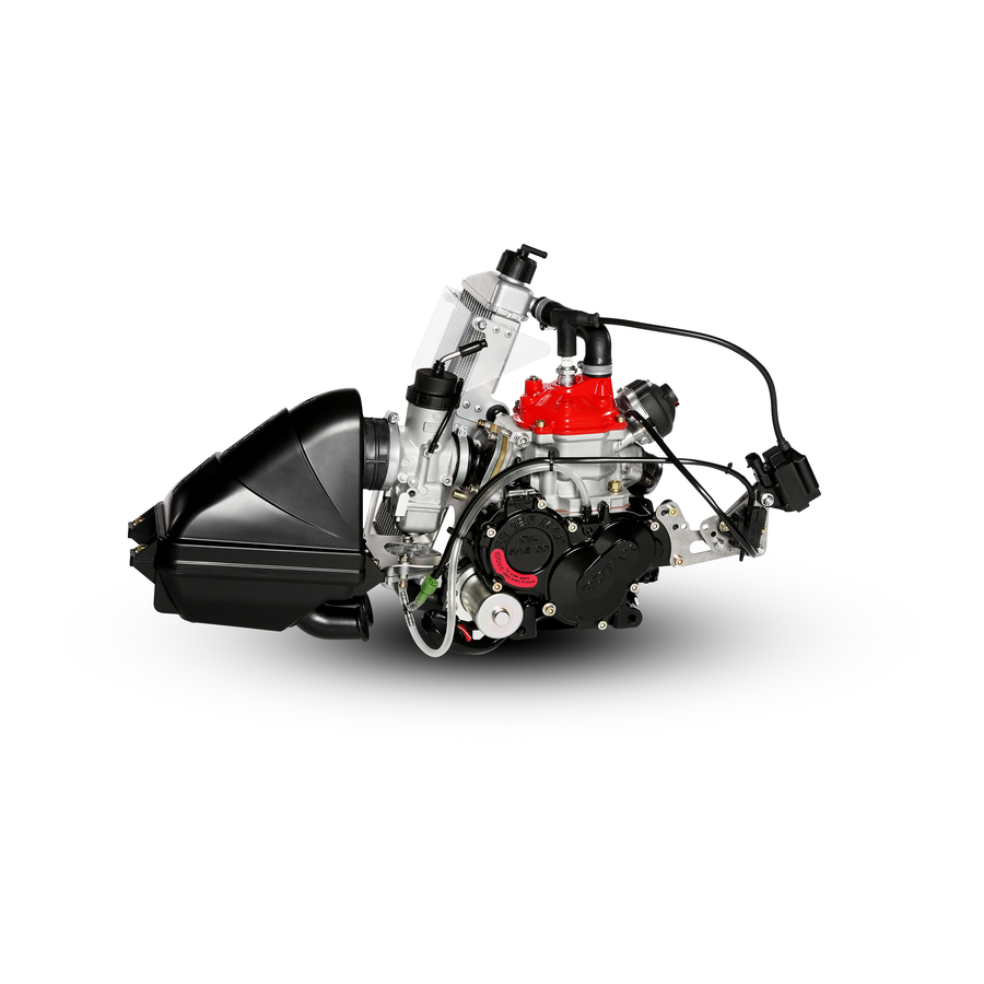
BRP-Powertrain REPAIR MANUAL 1) System description Engine in installed status Overview Part Function Engine Carburetor Exhaust system Figure 1 K00128 Effectivity: 125 MAX/125 Junior MAX/125 Mini Chapter 3 MAX/125 Micro MAX Edition 2 / Rev. 0 Page 3 December 01/2010... - Page 39 BRP-Powertrain REPAIR MANUAL NOTES Chapter 3 Effectivity: 125 MAX/125 Junior MAX/125 Mini MAX/125 Micro MAX Page 4 Edition 2 / Rev. 0 December 01/2010...
-
Page 40: Preparation
Procedure Disconnect tension springs (1) with spring hooks (part no. 251680). Loosen the nuts (2) on the shock mountings and remove the exhaust system. Effectivity: 125 MAX/125 Junior MAX/125 Mini Chapter 3 MAX/125 Micro MAX Edition 2 / Rev. 0... -
Page 41: Dismantling The Ignition Unit
Free the ignition transformer (2) at the locknut (5), washer (6) and 2 round buf- fers (8). Loosen and remove the starter (4) at the two screws (9). Chapter 3 Effectivity: 125 MAX/125 Junior MAX/125 Mini MAX/125 Micro MAX Page 6 Edition 2 / Rev. 0... - Page 42 Spark plug connector Ignition coil Pick up Starter M6 locknut 6.4 washer Ground wire Round buffer Cyl. screw M6x35 Figure 3 K00030 Effectivity: 125 MAX/125 Junior MAX/125 Mini Chapter 3 MAX/125 Micro MAX Edition 2 / Rev. 0 Page 7 December 01/2010...
-
Page 43: Removal Of The Fuel Line
Pull off fuel line (1) between fuel tank and fuel pump from the fuel pump (2). Fuel hose Graphic Part Function Fuel line Fuel pump Figure 4 K00030 Chapter 3 Effectivity: 125 MAX/125 Junior MAX/125 Mini MAX/125 Micro MAX Page 8 Edition 2 / Rev. 0 December 01/2010... - Page 44 Disconnect the cable bowden (2) from the nipple screw (3). Carburetor cable Graphic Part Function Carburetor cover Cable bowden Nipple screw Figure 5 K00133, K00134 Effectivity: 125 MAX/125 Junior MAX/125 Mini Chapter 3 MAX/125 Micro MAX Edition 2 / Rev. 0 Page 9 December 01/2010...
-
Page 45: Removal Of The Engine From The Kart Chassis
- Exhaust valve - Reed valve - Piston - Starter Engine support Graphic Part Function Engine mount clamps Figure 6 K00129 Chapter 3 Effectivity: 125 MAX/125 Junior MAX/125 Mini MAX/125 Micro MAX Page 10 Edition 2 / Rev. 0 December 01/2010... -
Page 46: Positioning The Engine On The Trestle Mounting Plate
(1), and fix it securely with the 4 fixing screws. Trestle mounting plate Graphic Part Function Trestle mounting plate Figure 7 K00108 Effectivity: 125 MAX/125 Junior MAX/125 Mini Chapter 3 MAX/125 Micro MAX Edition 2 / Rev. 0 Page 11 December 01/2010... - Page 47 BRP-Powertrain REPAIR MANUAL NOTES Chapter 3 Effectivity: 125 MAX/125 Junior MAX/125 Mini MAX/125 Micro MAX Page 12 Edition 2 / Rev. 0 December 01/2010...
-
Page 48: Preparation
Before installing the engine on the chassis the instal- lation instructions for the engine the installation in- structions of the chassis manufacturer must be read and understood. Effectivity: 125 MAX/125 Junior MAX/125 Mini Chapter 3 MAX/125 Micro MAX Edition 2 / Rev. 0... -
Page 49: Installation Of The Fuel Line
Procedure The installment of the cable bowden is identical to removal in reverse order. See also Chap. 3 Section: 2.4). Chapter 3 Effectivity: 125 MAX/125 Junior MAX/125 Mini MAX/125 Micro MAX Page 14 Edition 2 / Rev. 0 December 01/2010... -
Page 50: Installation Of The Ignition System
10 Nm (90 in.lb). Ignition unit Graphic Part Function Pick up Taptite screw or cyl. screw Figure 8 K00131, K00130 Effectivity: 125 MAX/125 Junior MAX/125 Mini Chapter 3 MAX/125 Micro MAX Edition 2 / Rev. 0 Page 15 December 01/2010... -
Page 51: Installation Of The Exhaust System
Before starting the engine, the operating instructions for the engine and the operating instructions of the chassis manufacturer must be read and understood. Chapter 3 Effectivity: 125 MAX/125 Junior MAX/125 Mini MAX/125 Micro MAX Page 16 Edition 2 / Rev. 0... - Page 52 BRP-Powertrain REPAIR MANUAL Chapter: 4 CYLINDER COMPONENTS This chapter describes the disassembly and assembly of the cylinder Contents components of the ROTAX 125 MAX engine. The description is divided into sections. Subject Page System description Page 3 Cylinder removal Page 5...
- Page 53 BRP-Powertrain REPAIR MANUAL NOTES Chapter 4 Effectivity: 125 MAX/125 Junior MAX/125 Mini MAX/125 Micro MAX Page 2 Edition 2 / Rev. 0 December 01/2010...
-
Page 54: System Description
1) System description Position on the engine Overview Part Function Cylinder Cylinder head cover Carburetor flange Exhaust valve Figure 1 K00010 Effectivity: 125 MAX/125 Junior MAX/125 Mini Chapter 4 MAX/125 Micro MAX Edition 2 / Rev. 0 Page 3 December 01/2010... - Page 55 BRP-Powertrain REPAIR MANUAL NOTES Chapter 4 Effectivity: 125 MAX/125 Junior MAX/125 Mini MAX/125 Micro MAX Page 4 Edition 2 / Rev. 0 December 01/2010...
-
Page 56: Cylinder Removal
Remove the cylinder with the socket set by unscrewing the four M8 collar nuts (1) from the crankcase. Remove the cylinder (2) from the crankcase. Remove the cylinder base gasket (3). Effectivity: 125 MAX/125 Junior MAX/125 Mini Chapter 4 MAX/125 Micro MAX Edition 2 / Rev. 0... -
Page 57: Dismantling Cylinder
Remove the combustion chamber insert (12) by unscrewing the 5 hex screws (13) crosswise the lock washer (14). Lift away the combustion chamber insert with lower (15) and upper O-rings (16). Chapter 4 Effectivity: 125 MAX/125 Junior MAX/125 Mini MAX/125 Micro MAX Page 6 Edition 2 / Rev. 0 December 01/2010... - Page 58 O-ring 105x2.5 Coolant thermostat Taptite screw M4x8 Thermostat retaining bracket Thermostat holder Compression spring Combustion chamber insert Hex screw M8x30 Effectivity: 125 MAX/125 Junior MAX/125 Mini Chapter 4 MAX/125 Micro MAX Edition 2 / Rev. 0 Page 7 December 01/2010...
-
Page 59: Removal Of Exhaust Socket
Remove the carburetor flange (5) with hose clamp (6) from the cylinder with the 5 cyl. screws (7). Remove the reed valve (8) and gasket (9) from the cylinder. Carburetor flange Graphic Chapter 4 Effectivity: 125 MAX/125 Junior MAX/125 Mini MAX/125 Micro MAX Page 8 Edition 2 / Rev. 0 December 01/2010... - Page 60 Reed valve Gasket Figure 3 K00026 2.2.7) Removal of exhaust valve (125 MAX only) The engine has a pneumatic exhaust outlet control to optimize the per- General formance characteristics. The exhaust pressure controls the valve bel- lows via the impulse bore. The exhaust valve piston pulls up the exhaust valve and thus provides a longer outlet control time.
-
Page 61: Removal Of Exhaust Valve (125 Max Only)
Release the valve rod housing (9) from the cylinder (12) with the 2 cyl. screws (10) with spring washers (11). Remove the gasket (13). Remove the exhaust valve (14) with O-ring (15) and stud (16). Removal of exhaust valve (125 MAX only) Graphic 16 14... -
Page 62: Removal Of Piston
Pull out the circlip (1) with the circlip puller (3). Use safety glasses! Press the piston rod out of the piston and con rod with the point of the special tool (3). Effectivity: 125 MAX/125 Junior MAX/125 Mini Chapter 4 MAX/125 Micro MAX Edition 2 / Rev. - Page 63 BRP-Powertrain REPAIR MANUAL Piston Graphic Part Function Circlip Circlip puller Special tool part no. 676035 Figure 5 K00035, K00153 Chapter 4 Effectivity: 125 MAX/125 Junior MAX/125 Mini MAX/125 Micro MAX Page 12 Edition 2 / Rev. 0 December 01/2010...
-
Page 64: Inspection Of Cylinder Parts
Inspect the impulse bore. Cylinder Graphic Part Function Possible lime deposits Slider duct Groove for O-ring Impulse bore Figure 6 K00027 Effectivity: 125 MAX/125 Junior MAX/125 Mini Chapter 4 MAX/125 Micro MAX Edition 2 / Rev. 0 Page 13 December 01/2010... -
Page 65: Inspection Of Piston And Piston Ring
Check the piston ring locking pin for wear. Piston and piston ring Graphic Part Function Feeler gauge Piston ring Figure 7 K00137,K00052 Chapter 4 Effectivity: 125 MAX/125 Junior MAX/125 Mini MAX/125 Micro MAX Page 14 Edition 2 / Rev. 0 December 01/2010... - Page 66 The piston clearance of a new piston/cylinder pairing should be 0.04 - 0.05 mm. Piston diameter Graphic 20 mm Part Function Micrometer Figure 8 K00096 Effectivity: 125 MAX/125 Junior MAX/125 Mini Chapter 4 MAX/125 Micro MAX Edition 2 / Rev. 0 Page 15 December 01/2010...
- Page 67 Check the needle cage (2) for cracks and abrasion. The circlips (3) are replaced at every repair. Part Function Piston pin Needle cage Circlip Figure 9 K00008 Chapter 4 Effectivity: 125 MAX/125 Junior MAX/125 Mini MAX/125 Micro MAX Page 16 Edition 2 / Rev. 0 December 01/2010...
-
Page 68: Inspection Of Spark Plug
Graphic Pos. 1 Pos. 3 Pos. 5 Pos. 4 Pos. 2 Part Function Spark plug Electrode Figure 10 K00031, K00073 Effectivity: 125 MAX/125 Junior MAX/125 Mini Chapter 4 MAX/125 Micro MAX Edition 2 / Rev. 0 Page 17 December 01/2010... -
Page 69: Inspection Of Cylinder Head Cover
Inspect combustion chamber insert for cracks (visual inspection). Check that spark plug thread (3) is in good condition. Inspect sealing surfaces for flatness and damage. Chapter 4 Effectivity: 125 MAX/125 Junior MAX/125 Mini MAX/125 Micro MAX Page 18 Edition 2 / Rev. 0... -
Page 70: Inspection Of Exhaust Socket
Inspect ball (1) of exhaust socket for wear and replace if applicable (wear depth max. 0.4 mm). Exhaust socket Graphic Part Function Exhaust socket (ball) Figure 13 K00024 Effectivity: 125 MAX/125 Junior MAX/125 Mini Chapter 4 MAX/125 Micro MAX Edition 2 / Rev. 0 Page 19 December 01/2010... -
Page 71: Inspection Of Carburetor Flange And Reed Valve
Inspect carburetor flange (4) for cracks, porosity or swelling and replace if ap- plicable. Carburetor port and valve guide Graphic Part Function Reed valves Reed petal Fastening Carburetor flange Figure 14 K00025 Chapter 4 Effectivity: 125 MAX/125 Junior MAX/125 Mini MAX/125 Micro MAX Page 20 Edition 2 / Rev. 0 December 01/2010... -
Page 72: Inspection Of Exhaust Valve (125 Max Only)
BRP-Powertrain REPAIR MANUAL 3.8) Inspection of exhaust valve (125 MAX only) Figure Instructions Step Procedure Clean oil or oil deposits from all parts with a suitable cleaning agent. Check the smooth movement of the exhaust valve (1) in the cylinder, if appli- cable remove carbon deposits on the outlet valve and in the cylinder. - Page 73 BRP-Powertrain REPAIR MANUAL NOTES Chapter 4 Effectivity: 125 MAX/125 Junior MAX/125 Mini MAX/125 Micro MAX Page 22 Edition 2 / Rev. 0 December 01/2010...
-
Page 74: Cylinder Assembly
BRP-Powertrain REPAIR MANUAL 4) Cylinder assembly 4.1) Installation of exhaust valve (125 MAX only) NOTES: Make sure that the components are in their correct General positions. The following special tools and equipment are required: Special tools Part number Description Part no. 899788... - Page 75 Graphic Part Function Cylinder Exhaust valve O-ring Gasket Valve rod housing Cyl. screws M6x16 Spring washers Figure 17 K00048, K00157 Chapter 4 Effectivity: 125 MAX/125 Junior MAX/125 Mini MAX/125 Micro MAX Page 24 Edition 2 / Rev. 0 December 01/2010...
- Page 76 NOTES: Turn the adjustment screw (15) into the valve cover (14) (13 clicks from inside) - this is the standard adjustment. Effectivity: 125 MAX/125 Junior MAX/125 Mini Chapter 4 MAX/125 Micro MAX Edition 2 / Rev. 0 Page 25...
- Page 77 Exhaust valve piston Hose spring 70 Hose spring 134 Compression spring Valve cover Adjustment screw Spring clip Figure 18 K00048, K00023, K00098,K00099 Chapter 4 Effectivity: 125 MAX/125 Junior MAX/125 Mini MAX/125 Micro MAX Page 26 Edition 2 / Rev. 0 December 01/2010...
-
Page 78: Installation Of Piston Pin
Place the installation tool with the cutout of the circlip down on the piston (4). Protect the piston with your hand and press into the piston with the hook ring. Effectivity: 125 MAX/125 Junior MAX/125 Mini Chapter 4 MAX/125 Micro MAX Edition 2 / Rev. - Page 79 NOTICE WARNING groove. Piston pin Graphic Part Function Circlip Mounting sleeve Installation tool Piston Figure 19 K00028, K00100, K00101, K00059 Chapter 4 Effectivity: 125 MAX/125 Junior MAX/125 Mini MAX/125 Micro MAX Page 28 Edition 2 / Rev. 0 December 01/2010...
-
Page 80: Cylinder Installation
Screw cylinder crosswise to the crankcase with the four studs. Tightening torque 24 Nm (18 ft.lb). Cylinder head Graphic Part Function Stud bolts Piston Cylinder Figure 20 K00102 Effectivity: 125 MAX/125 Junior MAX/125 Mini Chapter 4 MAX/125 Micro MAX Edition 2 / Rev. 0 Page 29 December 01/2010... -
Page 81: Installation Of Exhaust Socket
Check that the exhaust port is tightly seated on the cylinder. Exhaust socket Graphic SILASTIC Part Function Exhaust socket Gasket Cyl. screws M8x20 Cylinder Figure 21 K00024 Chapter 4 Effectivity: 125 MAX/125 Junior MAX/125 Mini MAX/125 Micro MAX Page 30 Edition 2 / Rev. 0 December 01/2010... - Page 82 Position the gasket (4) on the cylinder (5). Position the reed valve (6) and carburetor flange (7) and fasten with 5 fillister screws (8). Tightening torque 6 Nm (55 in.lb). Effectivity: 125 MAX/125 Junior MAX/125 Mini Chapter 4 MAX/125 Micro MAX Edition 2 / Rev.
- Page 83 Reed petal Valve detent Oval head screw M3x6 Gasket Cylinder Reed valve Carburetor flange Cyl. screw M6x25 Figure 22 K00025 Chapter 4 Effectivity: 125 MAX/125 Junior MAX/125 Mini MAX/125 Micro MAX Page 32 Edition 2 / Rev. 0 December 01/2010...
-
Page 84: Installation Of Combustion Chamber Insert
Insert O-ring (11) into the groove of the cylinder head cover (12). Tighten the cylinder head cover (12) crosswise with 4 cyl. screws (13). Tightening torque 10 Nm (90 in.lb). Effectivity: 125 MAX/125 Junior MAX/125 Mini Chapter 4 MAX/125 Micro MAX Edition 2 / Rev. - Page 85 Compression spring Thermostat retaining bracket Taptite screw M6x16 O-ring 23.3x2.4 O-ring 105x2.5 Cylinder head cover Cyl. screw M6x16 Figure 23 K00074,K00068 Chapter 4 Effectivity: 125 MAX/125 Junior MAX/125 Mini MAX/125 Micro MAX Page 34 Edition 2 / Rev. 0 December 01/2010...
-
Page 86: Inspection And Adjustment Of "Squich Gap
The squeeze edge must be within the specified tolerance NOTICE range. 1.05 mm + 0.25 mm (125 MAX only) 1.45 mm + 0.25 mm (125 Junior MAX only) NOTES: We recommend setting a squish gap in the upper tolerance range of the relevant model. - Page 87 “Installation of the cylinder” chapter for installation of the cylinder. Squish gap measurement Graphic Part Function Solder Vernier calliper Figure 24 K00075,K00076 Chapter 4 Effectivity: 125 MAX/125 Junior MAX/125 Mini MAX/125 Micro MAX Page 36 Edition 2 / Rev. 0 December 01/2010...
-
Page 88: Installation Of The Spark Plug
Proceed as follows to install the spark plug: Instructions Step Procedure Screw in spark plug hand-tight and use tightening torque 27 Nm (20 ft.lb). Effectivity: 125 MAX/125 Junior MAX/125 Mini Chapter 4 MAX/125 Micro MAX Edition 2 / Rev. 0 Page 37... - Page 89 BRP-Powertrain REPAIR MANUAL NOTES Chapter 4 Effectivity: 125 MAX/125 Junior MAX/125 Mini MAX/125 Micro MAX Page 38 Edition 2 / Rev. 0 December 01/2010...
- Page 90 BRP-Powertrain REPAIR MANUAL Chapter: 5 CRANKCASE This chapter describes the removal and installation of the crankcase of Contents the ROTAX 125 MAX engine. The description is divided into sections. Subject Page System description Page 3 Removal of the crankcase Page 5...
- Page 91 BRP-Powertrain REPAIR MANUAL NOTES Chapter 5 Effectivity: 125 MAX/125 Junior MAX/125 Mini MAX/125 Micro MAX Page 2 Edition 2 / Rev. 0 December 01/2010...
-
Page 92: System Description
BRP-Powertrain REPAIR MANUAL 1) System description Position on the engine Overview Part Function Crankcase Figure 1 K00138 Effectivity: 125 MAX/125 Junior MAX/125 Mini Chapter 5 MAX/125 Micro MAX Edition 2 / Rev. 0 Page 3 December 01/2010... - Page 93 BRP-Powertrain REPAIR MANUAL NOTES Chapter 5 Effectivity: 125 MAX/125 Junior MAX/125 Mini MAX/125 Micro MAX Page 4 Edition 2 / Rev. 0 December 01/2010...
-
Page 94: Removal Of The Crankcase
Remove needle pins (6) and thrust washer (7) from the water-pump shaft. Remove circlips (8) with circlip pliers. Remove the drive gear (9) from the crankshaft. Effectivity: 125 MAX/125 Junior MAX/125 Mini Chapter 5 MAX/125 Micro MAX Edition 2 / Rev. 0... - Page 95 Water-pump pinion Idle gear Needle pin Thrust washer 10.1/17/1 Circlip AV 20 Drive gear Balance gears O-ring 18x3.5 Figure 2 K00067 Chapter 5 Effectivity: 125 MAX/125 Junior MAX/125 Mini MAX/125 Micro MAX Page 6 Edition 2 / Rev. 0 December 01/2010...
-
Page 96: Disassemble Crankcase
Screw cyl. screws (1) evenly into the extraction thread and press the case halves evenly apart. Remove gasket from the case half. Remove water-pump shaft (2). Remove balance shaft (3) from the case. Effectivity: 125 MAX/125 Junior MAX/125 Mini Chapter 5 MAX/125 Micro MAX Edition 2 / Rev. 0 Page 7... - Page 97 BRP-Powertrain REPAIR MANUAL Crankcase Graphic Part Function Cyl. screw M6x60 Water pump shaft assembly Balance shaft Figure 3 K00103, K00011 Chapter 5 Effectivity: 125 MAX/125 Junior MAX/125 Mini MAX/125 Micro MAX Page 8 Edition 2 / Rev. 0 December 01/2010...
-
Page 98: Remove The Crankshaft
Gently tap the crankshaft with the plastic hammer (2) to remove the crankshaft from the case half. Crankshaft Graphic Part Function Crankshaft Plastic hammer Figure 4 K00036 Effectivity: 125 MAX/125 Junior MAX/125 Mini Chapter 5 MAX/125 Micro MAX Edition 2 / Rev. 0 Page 9 December 01/2010... - Page 99 Heat the two halves of the case to approx. 150 °C in the convection oven until the bearing can be tapped gently out. Chapter 5 Effectivity: 125 MAX/125 Junior MAX/125 Mini MAX/125 Micro MAX Page 10 Edition 2 / Rev. 0...
- Page 100 Oil seal Oil seal Oil seal Pick up Cyl. screw Air vent screw Countersunk screw Thrust washer Figure 5 K00036 Effectivity: 125 MAX/125 Junior MAX/125 Mini Chapter 5 MAX/125 Micro MAX Edition 2 / Rev. 0 Page 11 December 01/2010...
- Page 101 Case half Ball bearing (crankshaft) Ball bearing (balance shaft) Installation tool part no. 676030 Needle bearing Figure 6 K00013, K00039 Chapter 5 Effectivity: 125 MAX/125 Junior MAX/125 Mini MAX/125 Micro MAX Page 12 Edition 2 / Rev. 0 December 01/2010...
- Page 102 Ignition side crankcase Graphic Part Function Dowels Cylindrical pin Case half Ball bearing (crankshaft) Ball bearing (balance shaft) Figure 7 K00014 Effectivity: 125 MAX/125 Junior MAX/125 Mini Chapter 5 MAX/125 Micro MAX Edition 2 / Rev. 0 Page 13 December 01/2010...
-
Page 103: Conrod Set - Repair Set
The following special tools and equipment are required: Special tools Part number Description n.e. Press Crankshaft n.e. Dial gauge Part no. 276050 Repair kit Crankshaft Chapter 5 Effectivity: 125 MAX/125 Junior MAX/125 Mini MAX/125 Micro MAX Page 14 Edition 2 / Rev. 0 December 01/2010... - Page 104 Part number Description Part no. 295879 Crankshaft repair kit Connecting rod Thrust washers Connecting rod Needle bearing Connecting rod pin Effectivity: 125 MAX/125 Junior MAX/125 Mini Chapter 5 MAX/125 Micro MAX Edition 2 / Rev. 0 Page 15 December 01/2010...
- Page 105 Position crankshaft (3) with the thrust plate on bottom section of the tool (4) and make sure that the connecting rod pin is above the center hold of the bottom section. Chapter 5 Effectivity: 125 MAX/125 Junior MAX/125 Mini MAX/125 Micro MAX Page 16 Edition 2 / Rev. 0...
-
Page 106: Disassemble Crankshaft
Bottom section of tool Thrust pin Connecting rod pin Con rod Drive side crankshaft half Figure 10 K00082, K00083, K00084 Effectivity: 125 MAX/125 Junior MAX/125 Mini Chapter 5 MAX/125 Micro MAX Edition 2 / Rev. 0 Page 17 December 01/2010... -
Page 107: Inspect Crankshaft
If the maximum approved stroke (CS06) of the crankshaft is exceeded, the crankshaft must be realigned. See also Chap. 5 Section: 3.3.3). Chapter 5 Effectivity: 125 MAX/125 Junior MAX/125 Mini MAX/125 Micro MAX Page 18 Edition 2 / Rev. 0... - Page 108 Distance of crank webs CS07 48.95 mm - 49.05 mm 49.05 mm Thrust washer 1.0 mm 0.85 mm Figure 11 K00015, K00016, K00017 Effectivity: 125 MAX/125 Junior MAX/125 Mini Chapter 5 MAX/125 Micro MAX Edition 2 / Rev. 0 Page 19 December 01/2010...
-
Page 109: Crankshaft Out Of Round
Aligning the crankshaft Graphic Part Function Crankshaft half Vise Lever Figure 12 K00092 Chapter 5 Effectivity: 125 MAX/125 Junior MAX/125 Mini MAX/125 Micro MAX Page 20 Edition 2 / Rev. 0 December 01/2010... - Page 110 - check that all needle bearings are present Slide the new con rod (7) assembly with cage from the connecting rod pin (mounting device) onto the pressed-in connecting rod pin (5). Effectivity: 125 MAX/125 Junior MAX/125 Mini Chapter 5 MAX/125 Micro MAX Edition 2 / Rev.
-
Page 111: Assembly Of Crankshaft
Remove excess LOCTITE, otherwise the connecting rod may be damaged. Slide the drive-end crankshaft half (3) into the top section of the tool (9). Chapter 5 Effectivity: 125 MAX/125 Junior MAX/125 Mini MAX/125 Micro MAX Page 22 Edition 2 / Rev. 0... - Page 112 Connecting rod pin Connecting rod Gearbox end crankshaft half (engine end) Top section of tool Figure 14 K00088, K00089, K00095, K00090 Effectivity: 125 MAX/125 Junior MAX/125 Mini Chapter 5 MAX/125 Micro MAX Edition 2 / Rev. 0 Page 23 December 01/2010...
- Page 113 Assembly of crankshaft Graphic Part Function Bottom section of tool Top section of tool Press-out ring Figure 15 K00093, K00091, K00085 Chapter 5 Effectivity: 125 MAX/125 Junior MAX/125 Mini MAX/125 Micro MAX Page 24 Edition 2 / Rev. 0 December 01/2010...
-
Page 114: Crankcase-Inspection Of Components
Inspect the water pump shaft (6) in the region of the two oil seals for shaft for increased wear and replace if applicable. Inspect impeller (7) for damage or abnormal deformation and replace if applicable. Effectivity: 125 MAX/125 Junior MAX/125 Mini Chapter 5 MAX/125 Micro MAX Edition 2 / Rev. 0... - Page 115 Part Function Drive gear Idle gear Water-pump pinion Needle pin 5, 6, 7 Water pump shaft assembly Figure 16 K00019 Chapter 5 Effectivity: 125 MAX/125 Junior MAX/125 Mini MAX/125 Micro MAX Page 26 Edition 2 / Rev. 0 December 01/2010...
-
Page 116: Inspection Of Balance Shaft Drive
Wear limit value Bearing seat 14.96 mm - 14.99 mm 14.94 mm Bearing seat 24.97 mm - 24.99 mm 24.94 mm Effectivity: 125 MAX/125 Junior MAX/125 Mini Chapter 5 MAX/125 Micro MAX Edition 2 / Rev. 0 Page 27 December 01/2010... - Page 117 BRP-Powertrain REPAIR MANUAL Balance gears, balance shaft Graphic Part Function Balance gears O-ring Groove Figure 17 K00018, K00105 Chapter 5 Effectivity: 125 MAX/125 Junior MAX/125 Mini MAX/125 Micro MAX Page 28 Edition 2 / Rev. 0 December 01/2010...
-
Page 118: Inspection Of Crankcase
NOTES: If the roller bearings of the crankshaft or balance shaft are replaced, all oil seals for shaft must be replaced. Chapter 5 Effectivity: 125 MAX/125 Junior MAX/125 Mini MAX/125 Micro MAX Page 29 Edition 2 / Rev. 0 December 01/2010... - Page 119 BRP-Powertrain REPAIR MANUAL Crankcase Graphic Part Function Case halves Sealing surfaces Thread Main bearing lubrication hole Figure 18 K00037 Chapter 5 Effectivity: 125 MAX/125 Junior MAX/125 Mini MAX/125 Micro MAX Page 30 Edition 2 / Rev. 0 December 01/2010...
-
Page 120: Assembly Of Crankcase
Press in the needle bearing (2) to the limit stop with the installation tool (3) (part no. 676030) so the label on the needle bearing is facing outwards. Allow the crankcase halves to cool in this position. Effectivity: 125 MAX/125 Junior MAX/125 Mini Chapter 5 MAX/125 Micro MAX Edition 2 / Rev. - Page 121 Press in the first oil seal for shaft to the limit stop with the installation tool (7) (part no. 676021) so the closed end of the oil seal for shaft is visible. Chapter 5 Effectivity: 125 MAX/125 Junior MAX/125 Mini MAX/125 Micro MAX Page 32 Edition 2 / Rev.
- Page 122 (8) (part no. 676021) so the open end of the oil seal for shaft is visible. Allow the crankcase halves to cool in this position. Ignition end case half Graphic Effectivity: 125 MAX/125 Junior MAX/125 Mini Chapter 5 MAX/125 Micro MAX Edition 2 / Rev. 0...
- Page 123 Ball bearing (balance shaft) Lock washer Countersunk screw Oil seal M5x12 Mounting sleeve Ball bearing (crankshaft) Assembly punch Assembly punch Figure 20 K00042-K00046 Chapter 5 Effectivity: 125 MAX/125 Junior MAX/125 Mini MAX/125 Micro MAX Page 34 Edition 2 / Rev. 0 December 01/2010...
- Page 124 Position new gasket (4) on the ignition end crankcase half. NOTES: Adjustment of the clearance of the crankshaft is not re- quired. Effectivity: 125 MAX/125 Junior MAX/125 Mini Chapter 5 MAX/125 Micro MAX Edition 2 / Rev. 0 Page 35...
-
Page 125: Balance Shaft
Special tools Part number Description Part no. 877930 Trestle support assy. Crankcase Part no. 676052 Fixing plate for engine Crankcase Chapter 5 Effectivity: 125 MAX/125 Junior MAX/125 Mini MAX/125 Micro MAX Page 36 Edition 2 / Rev. 0 December 01/2010... - Page 126 Crankcase tightening Graphic 1-10 Graphic M6x60 M6x60 M6x45 M6x45 M6x45 M6x45 M6x45 M6x45 M6x45 M6x45 Effectivity: 125 MAX/125 Junior MAX/125 Mini Chapter 5 MAX/125 Micro MAX Edition 2 / Rev. 0 Page 37 December 01/2010...
- Page 127 BRP-Powertrain REPAIR MANUAL Part Function Crankcase gasket Figure 22 K00104, K00055 Chapter 5 Effectivity: 125 MAX/125 Junior MAX/125 Mini MAX/125 Micro MAX Page 38 Edition 2 / Rev. 0 December 01/2010...
-
Page 128: Installation Of Crankcase
Screw on gearbox cover (13) with 6 cyl. M6x25 screws (14) and 2 cyl. M6x30 screws. Tightening torque 10 Nm (90 in.lb). NOTES: Use gaskets to seal the oil drainage plug and oil level plug. Effectivity: 125 MAX/125 Junior MAX/125 Mini Chapter 5 MAX/125 Micro MAX Edition 2 / Rev. 0... - Page 129 BRP-Powertrain REPAIR MANUAL Crankcase Graphic Chapter 5 Effectivity: 125 MAX/125 Junior MAX/125 Mini MAX/125 Micro MAX Page 40 Edition 2 / Rev. 0 December 01/2010...
- Page 130 Water pump pinion 16 Z Idle gear Gasket Gearbox cover Cyl. screw M6x25 Cyl. screw M6x30 Figure 23 K00106, K00067, K00107 Effectivity: 125 MAX/125 Junior MAX/125 Mini Chapter 5 MAX/125 Micro MAX Edition 2 / Rev. 0 Page 41 December 01/2010...
- Page 131 BRP-Powertrain REPAIR MANUAL NOTES Chapter 5 Effectivity: 125 MAX/125 Junior MAX/125 Mini MAX/125 Micro MAX Page 42 Edition 2 / Rev. 0 December 01/2010...
- Page 132 REPAIR MANUAL Chapter: 6 CARBURETOR AND INTAKE SILENCER This chapter describes the disassembly and assembly of the carburetor Contents and intake silencer module of the ROTAX 125 MAX engine. The descrip- tion is divided into sections. Subject Page System description...
- Page 133 BRP-Powertrain REPAIR MANUAL NOTES Chapter 6 Effectivity: 125 MAX/125 Junior MAX/125 Mini MAX/125 Micro MAX Page 2 Edition 2 / Rev. 0 December 01/2010...
-
Page 134: System Description
REPAIR MANUAL 1) System description Position on the engine Overview Part Function Intake silencer Carburetor Fuel pump Figure 1 K00141 Effectivity: 125 MAX/125 Junior MAX/125 Mini Chapter 6 MAX/125 Micro MAX Edition 2 / Rev. 0 Page 3 December 01/2010... - Page 135 BRP-Powertrain REPAIR MANUAL NOTES Chapter 6 Effectivity: 125 MAX/125 Junior MAX/125 Mini MAX/125 Micro MAX Page 4 Edition 2 / Rev. 0 December 01/2010...
-
Page 136: Removal Of Carburetor And Intake Silencer
Unscrew 3 cyl. screws on the carburetor port (2). Remove carburetor (3) with intake silencer (4) with support bracket (5) and fuel pump (6). Effectivity: 125 MAX/125 Junior MAX/125 Mini Chapter 6 MAX/125 Micro MAX Edition 2 / Rev. 0... - Page 137 Carburetor and intake silencer Graphic Part Function Impulse pipe Cyl. screw Carburetor Intake silencer Support bracket Fuel pump Figure 2 K00141 Chapter 6 Effectivity: 125 MAX/125 Junior MAX/125 Mini MAX/125 Micro MAX Page 6 Edition 2 / Rev. 0 December 01/2010...
- Page 138 Remove the fuel pump (1) at the bottom of the support bracket (2) for the intake silencer. Fuel pump Graphic Part Function Fuel pump Support bracket Figure 3 K00124 Effectivity: 125 MAX/125 Junior MAX/125 Mini Chapter 6 MAX/125 Micro MAX Edition 2 / Rev. 0 Page 7 December 01/2010...
-
Page 139: Disassembly Of Carburetor
Disassemble the carburetor to the parts shown in Figure 4 and clean with fuel. Carburetor Graphic Needle Position Figure 4 K00064 Chapter 6 Effectivity: 125 MAX/125 Junior MAX/125 Mini MAX/125 Micro MAX Page 8 Edition 2 / Rev. 0 December 01/2010... - Page 140 Disassemble the intake silencer to the parts shown in Figure 5. Intake silencer Graphic Part Function Intake silencer case, bottom Intake silencer case, top Figure 5 K00063 Effectivity: 125 MAX/125 Junior MAX/125 Mini Chapter 6 MAX/125 Micro MAX Edition 2 / Rev. 0 Page 9 December 01/2010...
- Page 141 BRP-Powertrain REPAIR MANUAL NOTES Chapter 6 Effectivity: 125 MAX/125 Junior MAX/125 Mini MAX/125 Micro MAX Page 10 Edition 2 / Rev. 0 December 01/2010...
-
Page 142: Checking Components Of Carburetor And Intake Silencer
Check the tip of the needle valve (7). Carburetor Graphic Part Function Fuel filter Carburetor 3,4,5,6,7 Jets Lock washer Jet needle Figure 6 K00064 Effectivity: 125 MAX/125 Junior MAX/125 Mini Chapter 6 MAX/125 Micro MAX Edition 2 / Rev. 0 Page 11 December 01/2010... -
Page 143: Checking Fuel Pump
(3) and in case of doubt replace. Fuel pump Graphic Part Function Impulse pipe Fuel line Fuel overflow line Figure 7 K00065 Chapter 6 Effectivity: 125 MAX/125 Junior MAX/125 Mini MAX/125 Micro MAX Page 12 Edition 2 / Rev. 0 December 01/2010... -
Page 144: Checking Intake Silencer
Clean the silencer filter element (5) with a gasoline-oil mixture. Check the silencer filter element (5) for cracks. Check the support bracket (6) for cracks. Effectivity: 125 MAX/125 Junior MAX/125 Mini Chapter 6 MAX/125 Micro MAX Edition 2 / Rev. 0... - Page 145 Intake silencer case, bottom Intake silencer case, top Intake silencer tube Carburetor socket Filter element Support bracket Figure 8 K00063 Chapter 6 Effectivity: 125 MAX/125 Junior MAX/125 Mini MAX/125 Micro MAX Page 14 Edition 2 / Rev. 0 December 01/2010...
- Page 146 REPAIR MANUAL 4) Installation of carburetor and intake silencer 4.1) Assembly of carburetor NOTES: Use the gasket set ROTAX Part No. 293834. Carburetor Step Procedure The assembly of the parts is identical to the disassembly in reverse order. See also Chap. 6 Section: 2.1.2).
- Page 147 Procedure The assembly of the parts is identical to the disassembly in reverse order. See also Chap. 6 Section: 2.1.3). Chapter 6 Effectivity: 125 MAX/125 Junior MAX/125 Mini MAX/125 Micro MAX Page 16 Edition 2 / Rev. 0 December 01/2010...
-
Page 148: Installation Of Carburetor And Intake Silencer
Check the carburetor cable in the elbow for wear. Connect the fuel feed line (6) and the cable (7) to the carburetor. Connect the impulse pipe (8). Effectivity: 125 MAX/125 Junior MAX/125 Mini Chapter 6 MAX/125 Micro MAX Edition 2 / Rev. 0... -
Page 149: Assembly Of Intake Silencer
Part Function Carburetor Carburetor flange Hose clamp Intake silencer Support bracket Fuel line Carburetor cable Impulse pipe Figure 10 K00141 Chapter 6 Effectivity: 125 MAX/125 Junior MAX/125 Mini MAX/125 Micro MAX Page 18 Edition 2 / Rev. 0 December 01/2010... - Page 150 REPAIR MANUAL Chapter: 7 CLUTCH AND STARTER GEAR ASSEMBLY This chapter describes the disassembly and assembly of the clutch and Contents starter gear assembly module of the ROTAX 125 MAX engine. The description is divided into sections. Subject Page System description...
- Page 151 BRP-Powertrain REPAIR MANUAL NOTES Chapter 7 Effectivity: 125 MAX/125 Junior MAX/125 Mini MAX/125 Micro MAX Page 2 Edition 2 / Rev. 0 December 01/2010...
-
Page 152: System Description
REPAIR MANUAL 1) System description Position on the engine Overview Part Function Starter gear assembly Clutch drum Sprocket Figure 1 K00140 Effectivity: 125 MAX/125 Junior MAX/125 Mini Chapter 7 MAX/125 Micro MAX Edition 2 / Rev. 0 Page 3 December 01/2010... - Page 153 BRP-Powertrain REPAIR MANUAL NOTES Chapter 7 Effectivity: 125 MAX/125 Junior MAX/125 Mini MAX/125 Micro MAX Page 4 Edition 2 / Rev. 0 December 01/2010...
-
Page 154: Removal Of The Clutch And Starter Gear Assembly
Drain oil into a suitable vessel and dispose of it correctly. Oil draining Graphic Part Function Oil drain plug Figure 2 K00114 Effectivity: 125 MAX/125 Junior MAX/125 Mini Chapter 7 MAX/125 Micro MAX Edition 2 / Rev. 0 Page 5 December 01/2010... -
Page 155: Removal Of The Electric Starter
Ground cable Figure 3 K00078 2.2.1) Positioning the engine on the trestle mounting plate See also Chap. 3 Section: 2.6). Chapter 7 Effectivity: 125 MAX/125 Junior MAX/125 Mini MAX/125 Micro MAX Page 6 Edition 2 / Rev. 0 December 01/2010... -
Page 156: Removal Of The Clutch Drum
(6). It is pressed into the sprocket. Clutch drum Graphic Part Function Locking tool Fixation tool assembly Hex nut Effectivity: 125 MAX/125 Junior MAX/125 Mini Chapter 7 MAX/125 Micro MAX Edition 2 / Rev. 0 Page 7 December 01/2010... -
Page 157: Removal Of The Sprocket
Insert clutch drum (3) with installed sprocket (4) into the corresponding toothed cutout. Unscrew the hex nut (5) for the sprocket. Remove the sprocket from the clutch drum. Chapter 7 Effectivity: 125 MAX/125 Junior MAX/125 Mini MAX/125 Micro MAX Page 8 Edition 2 / Rev. 0 December 01/2010... - Page 158 11 teeth Part Function Fixation tool for sprocket (old model) Locating/locking device Clutch drum Sprocket Hex nut Figure 5 K00144,K00022 Effectivity: 125 MAX/125 Junior MAX/125 Mini Chapter 7 MAX/125 Micro MAX Edition 2 / Rev. 0 Page 9 December 01/2010...
-
Page 159: Removal Of The Clutch And Starter Gear Assembly
1 mm between the screws and housing. Pull out starter gear assembly. Remove starter reduction gear assembly (9) with the thrust washer (10) be- low. Chapter 7 Effectivity: 125 MAX/125 Junior MAX/125 Mini MAX/125 Micro MAX Page 10 Edition 2 / Rev. 0 December 01/2010... - Page 160 BRP-Powertrain REPAIR MANUAL Clutch and starter gear assembly Graphic Effectivity: 125 MAX/125 Junior MAX/125 Mini Chapter 7 MAX/125 Micro MAX Edition 2 / Rev. 0 Page 11 December 01/2010...
- Page 161 Fixation tool assembly Clutch Hex nut Puller assembly Cyl. screw M6x60 Starter reduction gear assembly Thrust washer Figure 6 K00079,K00151,K00145,K00115,K00145,K00006 Chapter 7 Effectivity: 125 MAX/125 Junior MAX/125 Mini MAX/125 Micro MAX Page 12 Edition 2 / Rev. 0 December 01/2010...
-
Page 162: Checking Components Of Clutch And Starter Gear
Function Clutch drum 2, 3 Thrust washer Needle cage Bearing sleeve (only sprocket with 11 teeth) Sprocket Figure 7 K00005 Effectivity: 125 MAX/125 Junior MAX/125 Mini Chapter 7 MAX/125 Micro MAX Edition 2 / Rev. 0 Page 13 December 01/2010... -
Page 163: Checking The Starter Reduction Gear Assembly
Starter reduction gear assembly Graphic NOTES Part Function Starter reduction gear assembly Gear wheel Gear wheel Thrust washer Figure 8 K00006 Chapter 7 Effectivity: 125 MAX/125 Junior MAX/125 Mini MAX/125 Micro MAX Page 14 Edition 2 / Rev. 0 December 01/2010... -
Page 164: Checking The Electric Starter
Check parts of the electric starter. Check teeth (2) for deformation and wear. Electric starter Graphic Part Function Starter cable Gear (teeth) Figure 9 K00034 Effectivity: 125 MAX/125 Junior MAX/125 Mini Chapter 7 MAX/125 Micro MAX Edition 2 / Rev. 0 Page 15 December 01/2010... -
Page 165: Electric Starter Repair Kit
Unscrew the starter housing screws (5). Electric starter Graphic Part Function Electrical feed Electric starter Cyl. screw Gearbox case Starter housing screws Figure 10 K00150 Chapter 7 Effectivity: 125 MAX/125 Junior MAX/125 Mini MAX/125 Micro MAX Page 16 Edition 2 / Rev. 0 December 01/2010... - Page 166 If necessary, unscrew the rubber seal and the ground pole from the starter support and clean them. Electric starter Graphic Figure 11 K00147,K00148,K00149 Effectivity: 125 MAX/125 Junior MAX/125 Mini Chapter 7 MAX/125 Micro MAX Edition 2 / Rev. 0 Page 17 December 01/2010...
- Page 167 Hold the rotor shaft with a suitable tool and secure the solenoid housing on the starter motor support. Installation of the electric starter Instructions See also Chap. 07, Section: 4.5). Chapter 7 Effectivity: 125 MAX/125 Junior MAX/125 Mini MAX/125 Micro MAX Page 18 Edition 2 / Rev. 0 December 01/2010...
-
Page 168: Checking The Clutch And Starter Gear Assembly
Clutch and starter gear assembly Graphic Part Function Hole (clutch) Clutch Starter gear assembly Taper (starter gear assembly) Figure 12 K00020 Effectivity: 125 MAX/125 Junior MAX/125 Mini Chapter 7 MAX/125 Micro MAX Edition 2 / Rev. 0 Page 19 December 01/2010... - Page 169 BRP-Powertrain REPAIR MANUAL NOTES Chapter 7 Effectivity: 125 MAX/125 Junior MAX/125 Mini MAX/125 Micro MAX Page 20 Edition 2 / Rev. 0 December 01/2010...
-
Page 170: Installation Of Clutch And Starter Gear Assembly
Starter reduction gear assembly Graphic Lithium-base grease Part Function Starter drive Figure 13 K00117 Effectivity: 125 MAX/125 Junior MAX/125 Mini Chapter 7 MAX/125 Micro MAX Edition 2 / Rev. 0 Page 21 December 01/2010... -
Page 171: Installing Starter Gear Assembly
The two cyl. screws (8) for fixing the starter drive cover (9) must be secured with LOCTITE 243. Tightening torque 5 Nm (44.25 in.lb). Chapter 7 Effectivity: 125 MAX/125 Junior MAX/125 Mini MAX/125 Micro MAX Page 22 Edition 2 / Rev. 0... - Page 172 BRP-Powertrain REPAIR MANUAL Starter gear assembly Graphic Effectivity: 125 MAX/125 Junior MAX/125 Mini Chapter 7 MAX/125 Micro MAX Edition 2 / Rev. 0 Page 23 December 01/2010...
- Page 173 Starter gear assembly Crankshaft Clutch Cyl. screw M6x12 Hex nut M20x1.5 Cyl. screw M6x25 Starter drive cover Figure 14 K00079,K00151,K00116,K00020,K00115 Chapter 7 Effectivity: 125 MAX/125 Junior MAX/125 Mini MAX/125 Micro MAX Page 24 Edition 2 / Rev. 0 December 01/2010...
-
Page 174: Assembling The Clutch Drum
11 teeth) (3) and press into the stop in the sprocket with the installation tool (part no. 676040). Installing bearing sleeve Graphic Part Function Bearing sleeve Bevel Sprocket 11 teeth Figure 15 K00158 Effectivity: 125 MAX/125 Junior MAX/125 Mini Chapter 7 MAX/125 Micro MAX Edition 2 / Rev. 0 Page 25 December 01/2010... -
Page 175: Installing Sprocket
Position clutch drum (6) on the sprocket. Secure hex nut (4) with LOCTITE 648 and tighten. Tightening torque 100 Nm (74 ft.lb). Chapter 7 Effectivity: 125 MAX/125 Junior MAX/125 Mini MAX/125 Micro MAX Page 26 Edition 2 / Rev. 0... - Page 176 Fixation tool for sprocket part no. 277362 Clutch drum Hex nut Installation tool Locating/locking device Clutch drum Figure 16 K00143, K00144,K00022 Effectivity: 125 MAX/125 Junior MAX/125 Mini Chapter 7 MAX/125 Micro MAX Edition 2 / Rev. 0 Page 27 December 01/2010...
-
Page 177: Installing Clutch Drum
Do not start the engine without the clutch drum; it will NOTICE WARNING not operate. Clutch drum Graphic LOCTITE 243 Chapter 7 Effectivity: 125 MAX/125 Junior MAX/125 Mini MAX/125 Micro MAX Page 28 Edition 2 / Rev. 0 December 01/2010... - Page 178 O-ring 12x2.5 Needle cage 15x19x17 Clutch drum Hex nut Thrust washer 10/22/1.5 Locking tool Fixation tool assembly Figure 17 K00159,K00142,K00079,K00151,K00140 Effectivity: 125 MAX/125 Junior MAX/125 Mini Chapter 7 MAX/125 Micro MAX Edition 2 / Rev. 0 Page 29 December 01/2010...
-
Page 179: Electric Starter
Connect the electrical and the ground cable to the starter. Electric starter Graphic Part Function O-ring Electric starter Cyl. screw M6x35 Figure 18 K00078 Chapter 7 Effectivity: 125 MAX/125 Junior MAX/125 Mini MAX/125 Micro MAX Page 30 Edition 2 / Rev. 0 December 01/2010... -
Page 180: Filling Gearbox With Oil
Screw in the vent screw (1) handtight. Adding oil. Graphic Part Function Vent screw Oil level plug Oil drain plug Figure 19 K00136 Effectivity: 125 MAX/125 Junior MAX/125 Mini Chapter 7 MAX/125 Micro MAX Edition 2 / Rev. 0 Page 31 December 01/2010... - Page 181 BRP-Powertrain REPAIR MANUAL NOTES Chapter 7 Effectivity: 125 MAX/125 Junior MAX/125 Mini MAX/125 Micro MAX Page 32 Edition 2 / Rev. 0 December 01/2010...
- Page 182 BRP-Powertrain REPAIR MANUAL Chapter: 8 WATER RADIATOR This chapter describes the removal and installation of the water radiator Contents module of the ROTAX 125 MAX engine. The description is divided into sections. Subject Page System description Page 3 Removing the water radiator...
- Page 183 BRP-Powertrain REPAIR MANUAL NOTES Chapter 8 Effectivity: 125 MAX/125 Junior MAX/125 Mini MAX/125 Micro MAX Page 2 Edition 2 / Rev. 0 December 01/2010...
-
Page 184: System Description
REPAIR MANUAL 1) System description Position on the engine Overview Part Function Radiator Cooling water hose Hose clamp Figure 1 K00120 Effectivity: 125 MAX/125 Junior MAX/125 Mini Chapter 8 MAX/125 Micro MAX Edition 2 / Rev. 0 Page 3 December 01/2010... - Page 185 BRP-Powertrain REPAIR MANUAL NOTES Chapter 8 Effectivity: 125 MAX/125 Junior MAX/125 Mini MAX/125 Micro MAX Page 4 Edition 2 / Rev. 0 December 01/2010...
-
Page 186: Removing The Water Radiator
Pull of cooling water hose (3) at the cylinder head cover (6). Unscrew the hose clamp (2) and pull the cooling water hose from the port. Effectivity: 125 MAX/125 Junior MAX/125 Mini Chapter 8 MAX/125 Micro MAX Edition 2 / Rev. - Page 187 Cooling water hose Graphic Part Function Radiator Hose clamp Cooling water hose Locknut Retaining plate Cylinder head cover Figure 2 K00120, K00121 Chapter 8 Effectivity: 125 MAX/125 Junior MAX/125 Mini MAX/125 Micro MAX Page 6 Edition 2 / Rev. 0 December 01/2010...
-
Page 188: Water Radiator -Inspection Of Components
Graphic Part Function Cooling fins Radiator Radiator cap Cooling water hose Retaining plate Rubber grommet Distance sleeve Figure 3 K00062 Effectivity: 125 MAX/125 Junior MAX/125 Mini Chapter 8 MAX/125 Micro MAX Edition 2 / Rev. 0 Page 7 December 01/2010... - Page 189 BRP-Powertrain REPAIR MANUAL NOTES Chapter 8 Effectivity: 125 MAX/125 Junior MAX/125 Mini MAX/125 Micro MAX Page 8 Edition 2 / Rev. 0 December 01/2010...
-
Page 190: Installation Of Water Radiator
Water cooler elbow Graphic Part Function Cooling water hose Connection (water radiator) Hose clamps Radiator cap Figure 4 K00122; k00123 Effectivity: 125 MAX/125 Junior MAX/125 Mini Chapter 8 MAX/125 Micro MAX Edition 2 / Rev. 0 Page 9 December 01/2010... -
Page 191: Installation Of The Water Radiator
Close the radiator cap. Check the cooling system for leaks by running the engine until it is at operating temperature. Chapter 8 Effectivity: 125 MAX/125 Junior MAX/125 Mini MAX/125 Micro MAX Page 10 Edition 2 / Rev. 0 December 01/2010... -
Page 192: Exhaust System
BRP-Powertrain REPAIR MANUAL Chapter: 9 EXHAUST SYSTEM This chapter describes the removal installation of the exhaust system Contents module of the ROTAX 125 MAX engine. The description is divided into sections. Subject Page System description Page 3 Removal of the exhaust system... -
Page 193: Effectivity: 125 Max/125 Junior Max/125 Mini
BRP-Powertrain REPAIR MANUAL NOTES Chapter 9 Effectivity: 125 MAX/125 Junior MAX/125 Mini MAX/125 Micro MAX Page 2 Edition 2 / Rev. 0 December 01/2010... -
Page 194: System Description
1) System description Position on the engine Overview Part Function Exhaust muffler After-muffler Ball socket Exhaust spring Figure 1 K00154 Effectivity: 125 MAX/125 Junior MAX/125 Mini Chapter 9 MAX/125 Micro MAX Edition 2 / Rev. 0 Page 3 December 01/2010... - Page 195 BRP-Powertrain REPAIR MANUAL NOTES Chapter 9 Effectivity: 125 MAX/125 Junior MAX/125 Mini MAX/125 Micro MAX Page 4 Edition 2 / Rev. 0 December 01/2010...
-
Page 196: Removal Of The Exhaust System
Figure Instructions Step Procedure Drill out the rivets of the cover (3). Remove old silencer baffle mat (4). Effectivity: 125 MAX/125 Junior MAX/125 Mini Chapter 9 MAX/125 Micro MAX Edition 2 / Rev. 0 Page 5 December 01/2010... -
Page 197: Assembling The Exhaust System
Step Procedure Roll up new isolating mat (4) and insert into the after-muffler (5). Install cover (6) and new rivets. Chapter 9 Effectivity: 125 MAX/125 Junior MAX/125 Mini MAX/125 Micro MAX Page 6 Edition 2 / Rev. 0 December 01/2010... -
Page 198: Installation Of The Exhaust System
Installation of the exhaust system Instructions Step Procedure The exhaust system is installed in reverse order of removal. See also Chap. 3 Section: 3.6). Effectivity: 125 MAX/125 Junior MAX/125 Mini Chapter 9 MAX/125 Micro MAX Edition 2 / Rev. 0 Page 7 December 01/2010... - Page 199 BRP-Powertrain REPAIR MANUAL NOTES Chapter 9 Effectivity: 125 MAX/125 Junior MAX/125 Mini MAX/125 Micro MAX Page 8 Edition 2 / Rev. 0 December 01/2010...
Need help?
Do you have a question about the 125 Max and is the answer not in the manual?
Questions and answers
Какая должна быть степень сжатия на моторе rotax Junior не эво ?