Table of Contents
Advertisement
Advertisement
Table of Contents
Troubleshooting

Related Manuals for Mitsubishi MOTORS M.U.T.-III

Summary of Contents for Mitsubishi MOTORS M.U.T.-III
- Page 1 M.U.T.-III Owner’s Manual Multi Use Tester < Ver. 20.0 > MITSUBISHI MOTORS...
- Page 2 Online Help prior to operation. This manual was written based on the Dec. 2010 version of the M.U.T.-III system. Please note that the information herein may not always agree with your version of the M.U.T.-III system due to system specification changes and version upgrades.
-
Page 3: Table Of Contents
Chapter 2 M.U.T.-III Functions..................8 2-1. Basic Functions ........................8 2-2. V.C.I. Functions ........................9 Chapter 3 Operating M.U.T.-III..................11 3-1. Starting and Shutting the M.U.T.-III System ................11 3-2. Screen Explanations.......................13 3-3. Basic Flow to Start Diagnosis ....................15 3-4. Option Settings ........................19 3-5. - Page 4 Chapter 9 ECU Reprogramming ................75 9-1. Process Flow Chart ........................75 9-2. Equipments..........................76 9-3. Data preparation on PC from Update CD-ROM..............77 9-4. Reprogramming Operation ( V.C.I. alone )................79 9-5. Reprogramming Operation ( V.C.I. - PC connected )..............86 9-6. Reprogramming by CAN communication................90 9-7.
- Page 5 • Violating this requirement results in the risk of a results in the risk of fire. ground fault, damage and/or electric shock. • M.U.T.-III as provided to dealers includes 12V accessory / cigarette lighter plug adapter to power M.U.T.-III during extended...
- Page 6 For Your Safety Warning The V.C.I. screen is liquid crystal display or Do not use the unit if the power AC adapter plug LCD. In the unlikely event that the display or cord is damaged or plugging into the outlet is breaks due to impact, do not let your skin loose.
- Page 7 PC or V.C.I. case using solutions such as thinner or benzene. Doing so may result in deterioration of the case surface. Prior to connecting the M.U.T.-III main harness between the V.C.I. and vehicle, turn the IG switch to OFF. • Connecting the V.C.I. harness with the IG switch ON may damage the V.C.I. programming.
-
Page 8: Chapter 1 Product Overview
• When working on a vehicle, be sure to apply the parking brake and set wheel chocks in place to prevent the car from moving. Driving Precautions • If you wish to use M.U.T.-III while driving the target vehicle, first verify that all parts are properly assembled. • While driving, always have an assistant operate M.U.T.-III. -
Page 9: Outline Drawing And Component Names
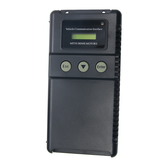
V.C.I. Outline Drawing and Component Names 1-2. V.C.I. Outline Drawing and Component Names The names of the V.C.I. components are indicated in the figure below. I/F cartridges M.U.T.-III main harness A (MB991910) M.U.T.-III main harness B (MB991911) M.U.T.-III main harness C (MB991914) (For US only) -
Page 10: M.u.t.-Iii Components Explanations
(MB991939). It is necessary to initialize a Compact Flash memory card by FAT16 and FAT32 format. (NTFS format cannot use) (3) M.U.T.-III Main Harness A (MB991910) Used when connecting the V.C.I. with vehicles that have only one 16-pin diagnosis connector. - Page 11 (10) I/F Cartridge Used to implement special functions that cannot be implemented with the V.C.I. unit alone. The following I/F cartridges used with M.U.T.-II can be used with M.U.T.-III as well: • SWS monitor cartridge (MB991806) • Tension meter cartridge (MB991669) •...
-
Page 12: Harness Connection Method
[2] While the PC is starting, connect the USB cable to the V.C.I. [3] After the PC boots to the M.U.T.-III main screen, connect the USB cable to the PC. Note: Disconnect the USB cable from the V.C.I. after the PC has shut down. However, if the USB cable is disconnected during use, a warning message indicating device disconnection such as that shown in Figure 1 appears. -
Page 13: Combination Chart Of Harness And Vehicle
Combination Chart of Harness and Vehicle 1-5. Combination Chart of Harness and Vehicle Use of the M.U.T.-III main harness A, B or C (US only) is determined by the type of diagnosis connector installed in the vehicle. The main harness, indicated with “O”, is used in combination with another harness indicated with “... - Page 14 Combination Chart of Harness and Vehicle Vehicle diagnostic connector - 16pin type to 16pin diagnosis connector Main harness A (MB991910) Vehicle diagnostic connector - 16pin type + 12 pin type to 12pin diagnosis connector to 16pin diagnosis connector Main harness B (MB991911) Vehicle diagnostic connector - 12pin type to 12pin diagnosis connector...
-
Page 15: Chapter 2 M.u.t.-Iii Functions
Basic Functions Chapter 2 M.U.T.-III Functions 2-1. Basic Functions Can be used with all vehicle installed electronic control systems (with built-in diagnostic functions) from model year 1984. Function Synopsis DTC readout Reads various diagnostic codes and displays the codes by name and number. -
Page 16: Functions
V.C.I. Functions 2-2. V.C.I. Functions <When V.C.I. and PC are connected> 2-2-1. Fault Diagnosis The system diagnoses faults by receiving instructions from the PC and communicating with the vehicle-installed ECU. When the system is connected to the PC, V.C.I. keys are disabled. - Page 17 V.C.I. Functions 2-2-4. V.C.I. Stand-alone Diagnosis You can read out DTCs with V.C.I. stand-alone by using a memory card, which is storing a diagnostic data transferred from PC. There is no need to carry PC or USB cable on the diagnosing vehicle.
-
Page 18: Chapter 3 Operating M.u.t.-Iii
Chapter 3 Operating M.U.T.-III 3-1. Starting and Shutting the M.U.T.-III System 3-1-1. Starting the M.U.T.-III System [Starting the PC] 1. Please turn on the power of M.U.T.-III PC. (Refer to the instructions of M.U.T.-III PC for details.) [To start up M.U.T.-III System] 2. - Page 19 STV Top Menu screen (illustrated on the left). Then press button on this screen to go to the M.U.T.-III Start screen. Press Exit button displayed on the lower right portion of the M.U.T.-III Start screen.
-
Page 20: Screen Explanations
Screen Explanations 3-2. Screen Explanations Starts “Scan Tool Viewer (STV)” system. < M.U.T.-III Start Screen > This manual contains information for proper operation of this system. Press this button first to start various interactive diagnoses. Exits the M.U.T.-III system. (refer to 3-1-2.) To set option settings, e.g. - Page 21 Screen Explanations < System Selection Screen > This screen is for specifying a system that you want to diagnose. As operation procedure differs according to the vehicle’s Model Year, please select “Up to 2005MY” or “From (2004MY in EU) 2006MY” firstly.
-
Page 22: Basic Flow To Start Diagnosis
3-3. Basic Flow to Start Diagnosis 3-3-1. Basic Flow of System Select Diagnosis (1) M.U.T.-III Start Screen Press STV (Scan Tool Viewer) button on the M.U.T.-III Start Screen. (2) STV Top Menu Press System Select button on the STV Top Menu screen. - Page 23 PC screen. (Not Available in US) Check Mode – To shorten sampling time of communication by changing the communication method between M.U.T.-III and ECU. This function is available in Data List, Drive Recorder, Actuator Test and Special Function. Emission Test -- To test the Evaporative Emission Control System of the vehicle.
- Page 24 Basic Flow to Start Diagnosis 3-3-2. Vehicle Information Setting Pressing button, on System Selection Screen or other vehicle-confirmation screen, displays the Vehicle Information Setting Screen. This screen allows you to modify the diagnosing vehicle information. (1) Vehicle Information Setting Screen -Currently selected information is displayed in each item’s field.
- Page 25 The vehicle information with Chassis No/VIN is retrieved, and the information is automatically input. * The database for this retrieval function is at that time when M.U.T.-III is released, for this reason vehicle information for the later vehicles might not be able to be retrieved.
-
Page 26: Option Settings
Keyboard set -- To select row of keys: Alphabetical-order or QWERTY. Select Language for display -- To select a language displayed in whole M.U.T.-III system and Service manuals. (Service manual will not be displayed unless the selected language has been downloaded.) -
Page 27: Useful Functions
3-5-2. Display “M.U.T.-III Owner’s Manual” Press M.U.T.-3 Manual button at the lower-left portion of the M.U.T.-III Start Screen, then this Adobe Acrobat Reader “M.U.T.-III Owner’s Manual” starts. Select “Bookmarks” tab at far left of the window. -When you select a title on the left column, you can jump into the corresponding page. -
Page 28: Chapter 4 Diagnosis Function
Diagnostic Trouble Code Chapter 4 Diagnosis Function 4-1. Diagnostic Trouble Code 4-1-1. Reading and Erasing Diagnostic Trouble Code (DTC) (1) Select a system that you want to diagnose on the System Selection screen. (For instruction on how to select a system, refer to 3-3-1) - In the explanation that follows, the method is explained using the MPI/GDI/Diesel system as a representative... - Page 29 Diagnostic Trouble Code 4-1-2. Interactive Fault Diagnosis Mode (1) Press DTC Procedures From Service Manual button. Note: It is not necessary to select DTC code to be diagnosed. (2) Vehicle Information Setting Screen -Currently selected information is displayed in each item’s field.
- Page 30 Diagnostic Trouble Code (5) Workshop Manual select screen Select manual to be browsed. Note: Select Vehicle button is not activated. (6) Shift of Workshop Manual Select content you want from Workshop Manuals displayed on the task-bar button of the screen. Note: Workshop Manual in different kind of vehicles cannot be browsed simultaneously.
-
Page 31: Data List (Service Data Monitor)
Data List 4-2. Data List (Service Data monitor) 4-2-1. Display of Data List (1) Displaying Text style Press Data List button on the screen 4-1-1(2), and the left screen will be displayed. -- Select item -- to 4-2-2(1). -- 4items/4Graphs display -- to (2) -- 4items/View Graph (overwrite) -- to (3) -- Displays “Data List Reference Table”... - Page 32 Data List 4-2-2. Details of Data List Screen (1) Displaying Item Selection • Item Group Select Select a group of the data to be displayed, and press button. • Item Select By default, none of the items are selected. Select an item that you wish to display, and apply the selection using buttons.
- Page 33 Data List (2) Record Data 1. Graph data is paused by pressing button, and the data can be saved on the PC automatically. -- OK -- to 2 --Cancel (Not save the data and return to the pause screen. Pressing button starts data list again.) 2.
-
Page 34: Actuator Test
Actuator Test 4-3. Actuator Test Press Actuator Test button on the screen 4-1-1.(2), then go to 4-3-1 or 4-3-2 to proceed, according to the type of the screen, A or B. 4-3-1. Actuator Test (Type A) If the screen illustrated on the left appears…. (1) Select a test item and press button to activate actuator. - Page 35 Actuator Test 4-3-2. Actuator Test (Type B) If the screen illustrated on (2) or (3) appears…. (1) Press button located next to item name, and select a test item from the pull-down menu. -When the selected item has no parameters -- to (2) -When the selected item has parameters -- to (3) --Displays “Actuator Test Reference Table”...
- Page 36 Actuator Test (5) Actuator Test Executing If you want to interrupt the Actuator Test, press button. When completes the test, a dialog box appears. Press button. returns to screen (2) or (3). Data List simultaneous display (Text) Refer to (1)-(5). --Select items for Data list display Data List simultaneous display (Graphs) Refer to (1)-(5).
-
Page 37: Stand-Alone Diagnosis
V.C.I. Stand-alone Diagnosis 4-4. V.C.I. Stand-alone Diagnosis This function allows you to read out DTCs by V.C.I. alone, without carrying PC or USB cable into the vehicle, using a memory card that is storing a diagnostic data transferred from PC. Once 4-4-1 has been performed, you should precede just 4-4-2 operations until a new database will be distributed. - Page 38 V.C.I. Stand-alone Diagnosis (5) Drive Selection Select the appropriate drive (removable disk drive) to save the data, then press button. Data transfer takes about 5 minutes at Windows XP and Windows Vista. (6) The data has been saved. Press button. (7) Before you remove the memory card, double-click the icon for removal of adaptor displayed on the bottom-right corner.
- Page 39 V.C.I. Stand-alone Diagnosis 4-4-2. Reading DTCs by V.C.I. stand-alone (1) Insert the memory card, which is storing V.C.I. stand-alone diagnosis data, into the card adaptor, then insert them into V.C.I. main unit. -Connect the V.C.I. main unit and the diagnosing vehicle Connect with Main harness A or B with an appropriate main harness securely.
- Page 40 V.C.I. Stand-alone Diagnosis Display Example: (5) System Selection <System Select> Press button to browse the list until the LCD displays MPI/GDI/DIESEL the system you want to diagnose, then press (Enter) button. IMMOBILIZER ELC-AT/CVT ABS/ASC/ASTC ・ ・ ・ (6) Option Selection Display Example: If the system has a loading option, the ‘Option Select’...
- Page 41 V.C.I. Stand-alone Diagnosis 4-4-3. Erasing DTCs by V.C.I. stand-alone (1) Press (Enter) button. Display Example: Press Enter to Erase DTCs (2) Press (Enter) button, returns to (1). Display Example: Erase DTCs Complete! NOTE: The following systems, which need special process to read DTCs, are out of target for the V.C.I.
-
Page 42: All Dtcs
-All the systems are selected by default. -Select systems to read DTCs having the box checked Note: ( ), then press button. M.U.T.-III for EU countries, the options (Clicking the box deletes the mark) for Model Year is classified in “Up to 2004 MY”... - Page 43 All DTCs When selecting “From 2006 MY” The System List and the Vehicle Information list (*a) (*c) appear on the screen. 1. Confirm the contents of the Vehicle Information list (*c) -When the contents are not describing the vehicle, press button to correct the information.
- Page 44 All DTCs (6) DTCs checking (7) DTCs checking are complete. Press button. (8) Results (*a) -Indicates presence or absence of DTCs on the results field as below. “OK” : DTCs are not detected “TC” : DTCs are detected “ ” : Unchecked (out of the check system), Not equipped or communication error (*d) -All detected DTCs are listed.
-
Page 45: Chapter 5 Special Function (Calibration & Setting)
ECU Information / Learned Value Reset Chapter 5 Special Function (Calibration & Setting) 5-1. ECU Information 5-1-1. Displays ECU Information (KWP2000 on CAN only) (1) Function Select Select a system on the System Selection screen. (For instruction on how to select a system, refer to 3-3-1) Then press Special Function button on Function... -
Page 46: Steering Angle Sensor Calibration
Steering Angle Sensor Calibration 5-3. Steering Angle Sensor Calibration 5-3-1. Steering Angle Sensor Calibration (1) System Select Select “Steering Angle Sensor” on the System Selection screen. (For instruction on how to select a system, refer to 3-3-1) (2) Function Select Press Special Function button. - Page 47 Steering Angle Sensor Calibration (6) Study Completed --OK -- to (4). (7) Re-calibration If the SAS needs re-calibration, press the button to execute SAS initialization. --Cancel -- to (4). (8) Initialization Press the button to execute. (9) Clear DTCs Confirmation --Start -- to (10).
-
Page 48: Lateral G Sensor Calibration
Lateral G Sensor Calibration 5-4. Lateral G Sensor Calibration 5-4-1. Lateral G sensor Calibration (1) System Select Select “ABS/ASC/ASTC” on the System Selection screen. (For instruction on how to select a system, refer to 3-3-1) (2) Function Select Press Special Function button. (3) Special Function menu Select Press Sensor Calibration button. -
Page 49: Chapter 6 Drive Recorder
How to Record the Data Chapter 6 Drive Recorder 6-1. How to Record the Data There are two ways for recording the data, “Recording by V.C.I. alone (6-1-1)”, and “Recording on PC with displaying data (6-1-2)”. Please select one of them and follow the procedure. 6-1-1. - Page 50 How to Record the Data (4) Item Select • Select an item you wish to record and apply the selection-using button. --Inserts the item selected in “Available items list” into the selected area of “Selected items list”. --Inserts the item selected in “Selected items list” into the lowermost area of “Available items list”.
- Page 51 How to Record the Data (6) When “Diagnosis Code Trigger” is selected in (5), the left screen appears. • Select an item to be the trigger, and press button. -- to (8). (If Threshold Trigger is selected as well, go to (7)) (7) When “Threshold Trigger”...
- Page 52 How to Record the Data (9) View V.C.I. Regeneration Data 1. For the data recorded in the selected V.C.I. recording area, the settings of the items are displayed. -- Deletes data recorded in the V.C.I. Select a data you wish to delete, and press this button -- to 2 -- Cancel -- to (8) 2.
- Page 53 How to Record the Data (13) The contents check of setting (3/3) (Only if selected in (7)) The list of Threshold conditions appears. -- to check recording setting -- to check set items Press button transmits the settings to the V.C.I.-- to (14) (14) Transmit Confirmation By pressing button on screen (11)/(12)/(13), the record...
- Page 54 How to Record the Data (18) Starting Recording To start recording, turn off the engine first, and then turn the ignition switch ON or start the engine and turn the V.C.I. power switch ON. Recording begins after communication initialization. Note: -The number in parenthesis on the V.C.I.
- Page 55 How to Record the Data 6-1-2. Recording on PC with displaying data This section describes the operation for saving the data at a file with displaying it as the set up record conditions on PC. (1) System Select Select a system for which the drive recorder is to be used on the System Selection screen.
- Page 56 How to Record the Data (4) Item Select • Select an item you wish to record and apply the selection-using button. --Inserts the item selected in “Available items list” into the selected area of “Selected items list”. --Inserts the item selected in “Selected items list” into the lowermost area of “Available items list”.
- Page 57 How to Record the Data (6) When “Diagnosis Code Trigger” is selected in (5), the left screen appears. • Select an item to be the trigger, and press button. -- to (8). (If Threshold Trigger is selected as well, go to (7)) (7) When “Threshold Trigger”...
- Page 58 How to Record the Data (9) Graph display item selection Select the items you wish to display on the graph. -Selected 4items are displayed during the recording. -The items not selected are not displayed on graph but the data are recorded. -- OK -- to (8) (10) Enter the record information (memorandum).
- Page 59 How to Record the Data (14) Recording Data [Graph] It saves at the file, expressing data as the set-up record conditions. The four items chosen on (9) are indicated by graph as the left screen (a). [Text] When “Text” was chosen on (8), and a drive recorder is set up, it saves at a file, acquiring and expressing data as the set-up record conditions.
- Page 60 How to Record the Data 6-1-3. Reuse past setting condition Record (Read Setting Conditions) button allows you to restore past recording conditions so that you can execute recording under the same conditions as those used with previously recorded data files. (1) Press Record (Read Setting Conditions) button on the Drive Recorder function menu.
-
Page 61: Recorded Data Handling
Recorded Data Handling 6-2. Recorded Data Handling 6-2-1. Transmit data on V.C.I. to PC To view the data recorded on V.C.I., you need to transfer it from V.C.I. to PC first. Connect V.C.I. and PC using a USB cable and operate following procedures. (1) You can transfer the data using only V.C.I. - Page 62 Recorded Data Handling (5) Display of V.C.I. Data The status of V.C.I. recording area is displayed. Select a data to be transferred into PC, and press button. -- to (6) When you wish to delete a data, select it and press button.
- Page 63 Data List records. (refer to 4-2-2.(2)) Caution: About “CSV file” If you open the CSV file on M.U.T.-III using EXCEL, never overwrite and save it. (However, they are allowed after the file is transferred from M.U.T.-III to another PC or copied in...
- Page 64 Recorded Data Handling (4) Edit Data Information 1. Select a file to edit and press button to display the screen illustrated on the left, where you can edit the record information that was entered in 6-1-1(10) or 6-1-2(10). Press button. 2.
- Page 65 Recorded Data Handling 2. Drive Select Select a drive for saving the data files, and press button. 3. Data Saved The files are saved. Press button. (7) Data Storing 1. The data saved in a removable disk before can be stored into the PC.
-
Page 66: Display And Analysis Of The Recorded Data
Display and Analysis of the Recorded Data 6-3. Display and Analysis of the Recorded Data 6-3-1. Display the recorded data (1) Press Special Function on the STV Top Menu. Then select the System Functions tab on the upper part of the screen, and press Drive Recorder (Display only),. - Page 67 Display and Analysis of the Recorded Data Displaying Graph 1 --Text data --Graph data 2 --Select item (to (4)) --Edits extraction conditions (to 6-3-2.(1)) --Jumps to a trigger point --Saves data (to 6-3-2.(3)) --Displays a correlation diagram (to 6-3-3.(1)) --Displays a distribution chart (to 6-3-3.(2)) --Change Time Scale --Change Data Scale...
- Page 68 Display and Analysis of the Recorded Data 6-3-2. Extraction and Search of the recorded data Recorded data can be extracted or retrieved for display on predetermined conditions. <Extraction: Only matching data will be displayed> <Retrieval: Matching data will be displayed with *(asterisk)> Time range, threshold of item etc.
- Page 69 Display and Analysis of the Recorded Data (2) Conditions setting for data search Condition setting screen shown on the left will be displayed after pressing button on text data display screen. • Select an item and edit its condition in Condition editing table appearing at the bottom of the screen.
- Page 70 Display and Analysis of the Recorded Data 6-3-3. Diagram and Chart (1) Setting the Correlation Diagram Pressing button on the screen illustrated in 6-3-1(3) displays the correlation diagram settings screen as illustrated on the left. Setting the target data time range, item names and data display range and pressing button displays the correlation diagram.
- Page 71 Display and Analysis of the Recorded Data 6-3-4. Other Functions (1) Changing Item Display Order On the data list display screen, you can change the display order of the items. The change is possible for both text display and graph display. -Selecting the name display area of an item fixes the item.
-
Page 72: Chapter 7 Sws Monitor
(For instructions on how to select a system, refer to 3-3-1) Note: SWS monitor cartridge is required in M.U.T.-III as well for SWS monitor. For details regarding how to connect the cartridge and harness, see the M.U.T.-II reference manual (Pub. No. - Page 73 SWS Monitor Operation (4) This screen appears depending on vehicle SWS version. Select a specification of communication between doors of the vehicle that you monitor, and press button. [New communication between doors] Power windows controlled multiplex communication between driver’s seat Power window module and other Power window switches.
- Page 74 SWS Monitor Operation (3) Displaying Text style If you press How to Check ECU’s button, you can view the Service Manual. (Not Available in US) 7-1-3. Data List (1) When pressing Data List on SWS monitor menu screen, some vehicle SWS version shows “Item Group List” illustrated on the left.
- Page 75 SWS Monitor Operation (5) Simulated Vehicle Speed Output The Simulated Vehicle speed output function displays the simulated vehicle speed and Data List simultaneously. Speed output can be changed in 1 mph or 10 mph increments using the speed adjusting buttons. --Unit: 1mph --Unit: 10mph --View graph...
- Page 76 SWS Monitor Operation 7-1-5. Drive Recorder Function Record --Records data such as Data List in the built-in memory of SWS monitor cartridge. -- to (2). Data Display --Displays the data recorded with the drive recorder. -- to (9). (2) The left figure is displayed when the last record remains. Erase recorded data in SWS monitor cartridge, before record data.
- Page 77 SWS Monitor Operation (5) Setting the Recording Time The recording time can be set from 0day 0h 0min to 5days 0h 0min. If you do not wish to set a recording time, press button without setting the time. The day and time are set using -Day --Unit: 1 day -Hour-- Unit: 1h,...
- Page 78 SWS Monitor Operation (9) Data Display Select Data Display button on the screen of (1). You can also display recorded data by returning to the STV Top Menu, selecting Special Functions, then selecting the system function SWS Drive Recorder. In this case, you can view the data without connecting V.C.I.
- Page 79 SWS Monitor Operation 7-1-6. Keyless Entry Function (1) When pressing Keyless Entry button on 7-1-1.(5), the screen illustrated on the left appears. Keyless ID Regist --Delete and register ID -- to (2) Recept Inspect --Check for signal detection. -- to (5) (2) Deleting Keyless ID When pressing Keyless ID Regist...
- Page 80 SWS Monitor Operation 7-1-7. Customize Function (1) Displaying Data When pressing Custom Function button on 7-1-1.(5), a massage indicating that a short time is required to display the data appears. When the data illustrated on the left displayed, select an item to customize and press button.
-
Page 81: Chapter 8 Can Bus Diagnosis
8-1. Diagnosing the CAN Bus < CAUTION > • When you execute CAN Bus diagnosis, use M.U.T.-III main harness A. • When you execute CAN Bus diagnosis, halt the vehicle. • Calibrate ohmmeter to 0 point periodically for proper diagnosis. (refer to 11-3-2.) 8-1-1. -
Page 82: Chapter 9 Ecu Reprogramming
Chapter 9 ECU Reprogramming Notes: • This function enables the program installed in ECU to be reprogrammed using M.U.T.-III. • As VIN or other setting information on ECU is not erased by this reprogramming, you do not need to rewrite VIN. -
Page 83: Equipments
CF Memory card (1GB) MB992228 with V.C.I. alone CF Memory Card Adaptor MB991939 V.C.I. MB991824 M.U.T.-III Main Harness A (44-16) MB991910 M.U.T.-III Main Harness B (44-16/12) MB991911 Reprogramming adapter Harness (12-13) MB991855 Remarks *1: Vehicle which is only equipped with a 16 pin diagnosis connector. -
Page 84: Data Preparation On Pc From Update Cd-Rom
Data preparation on PC from Update CD-ROM 9-3. Data preparation on PC from Update CD-ROM 9-3-1. PC Update Operation (CD-ROM --> PC) < CASE 1 > (1) When an Update CD-ROM of ECU reprogramming data is distributed newly, insert the CD-ROM into CD-drive on PC. (2) Press Special function button on STV Top Menu. - Page 85 (5) Update is unnecessary The ECU Reprogramming data in M.U.T.-III is in the newest state. It is not necessary to update ECU Reprogramming data. Click the “OK” button, this update application is ended.
-
Page 86: Reprogramming Operation ( V.c.i. Alone )
-In case an update CD-ROM is set in the PC with update undone, data update starts. (refer to 9-3-1(4)) (4) Press Memory card transfer button. ALL reprogramming data in the M.U.T.-III PC are transferred to the memory card. Caution -Do not remove the memory card from PC. - Page 87 Reprogramming Operation ( V.C.I. alone ) (6) Press button when the message “It transfers data to the memory card. Are you ready?” appears (7) Data transfer The progress bar is displayed during the transfer. (8) The data transfer is complete. Press button.
- Page 88 (To connect Main harness B and 13pin diagnosis connector) (3) After verifying the ignition switch position at LOCK (OFF), connect the M.U.T.-III Main harness B or A to the diagnosis connector. (4) Turn Ignition switch on, and turn V.C.I. main switch on.
- Page 89 Reprogramming Operation ( V.C.I. alone ) 9-4-3. Data Retrieval (Memory card --> V.C.I.) (a). Automatic Data Retrieval (b). Select and Load Data (c). (Special case) (a). Automatic Data Retrieval (1) Select “Automatic RPG” in main menu and press Enter key. <Main Menu>...
- Page 90 Reprogramming Operation ( V.C.I. alone ) (b). Select and Load Data (1) Select “Load RPG file” in main menu by key, and press <Main Menu> Enter key. 3 Load RPG file (2) Select a reprogramming data file by key, and press Enter <File Selection>...
- Page 91 Reprogramming Operation ( V.C.I. alone ) 9-4-4. Reprogramming ECU (V.C.I. --> Vehicle ECU) In case of Engine ECU (1) ECU parts No. and ROM-ID No. are displayed. Part# MD351868 Press Enter key to start reprogramming. ROM-ID 120926 ESC / key : restart V.C.I. Auto change in 4 sec* * : By pressing key, immediately move to next.
- Page 92 Reprogramming Operation ( V.C.I. alone ) (2) 5 steps progress is displayed while reprogramming. In Progress Caution: STEP1 ..• Do not press any key during reprogramming automatically proceeding. In Progress STEP2 ..• Do not turn off V.C.I power or IG switch during reprogramming.
-
Page 93: Reprogramming Operation ( V.c.i. - Pc Connected )
- Transfer of stored Reprogramming data to Memory card. Connect PC and V.C.I., and prepare following steps. 1. Connect M.U.T.-III Main Harness B or A to V.C.I. securely. 2. After verifying the ignition switch position at LOCK (OFF), connect the M.U.T.-III Main harness B or A to the vehicle’s diagnosis connector. - Page 94 Reprogramming Operation ( V.C.I. - PC connection ) 9-5-2. Data Search & Transfer (PC --> V.C.I.) (a). Automatic Data Search (b). Database File display (c). Reprogramming Data Selection (d). Search (a). Automatic Data Search (1) Press Automatic Reprogramming (K-line) button on the function menu, then the left dialog box appears.
- Page 95 -The displayed data as default is in the folder shown below. C:¥Program Files¥MUT3¥RPGDATA This directory is the default reprogramming data pool of M.U.T.-III, referred from 9-4-1, 9-5-2(a),(b),(d). -After completing the data transfer, ECU reprogramming will start sequentially. (refer to 9-5-3.)
- Page 96 Reprogramming Operation ( V.C.I. - PC connection ) (d). Search To search the reprogramming data by inputting ECU Part No., ROM-ID, or Data No. (1) Press Search button on the function menu, then the left screen appears. Input search key info in the input column, then press button.
-
Page 97: Reprogramming By Can Communication
Reprogramming by CAN communication 9-6. Reprogramming by CAN communication (1) Press Special Function button on STV Top Menu. (2) Press ECU reprogramming button. (3) Select an appropriate button. Automatic Reprogramming (K-line) -- to 9-5-2(a) - Automatically searches appropriate Reprogramming data stored in PC. Database File Display (K-line) -- to 9-5-2(b) - Shows the list of Reprogramming data stored in PC. - Page 98 Reprogramming by CAN Communication (a). Automatic Reprogramming (1) Press Automatic Reprogramming (CAN) button. (2) Vehicle choice -Selected Model year and Model Code of the vehicle are indicated. -Select a system (ECU) and loading option, and press button. -If you select other Model year and Model code,press button and select model.
- Page 99 Reprogramming by CAN communication (4) Data search Searching the target reprogramming data. < Unnecessary reprogramming > ・ Appropriate reprogramming data is not released. Unnecessary ・ Onboard ECU Part No. and S/W reprogramming Part No. are indicated. < Complete reprogramming > Complete ・...
-
Page 100: Troubleshooting Of Reprogramming
Reprogramming by CAN Communication / Troubleshooting of Reprogramming (b). Database File display Press Database File Display (CAN) button on the function menu, then the left screen appears. Reprogramming data files in the hard disk are listed. NOTE: Can’t possible update at select data from data list. 9-7. -
Page 101: Chapter 10 Computer Diagnosis
Operation method of MiEV Computer Diagnosis Chapter 10 Computer Diagnosis 10-1. Operation method of MiEV Computer Diagnosis 10-1-1. Setting and execution of MiEV Computer Diagnosis (1) You can perform the MiEV computer diagnosis. Press Special Function button on the STV Top Menu. - Page 102 Operation method of MiEV Computer Diagnosis (4) Input of Vehicle Information Confirm the contents of Diagnosis Vehicle information list on the screen. - If the information is just the vehicle to be perform diagnosis, press - to (5) - If the information is not the vehicle you want, press to select appropriate one.
- Page 103 Operation method of MiEV Computer Diagnosis (8) DTC Check The DTC Check is executed by pressing the button after setting of the system and the option select. (9) High-Voltage Battery Check In the power switch of the vehicle is in the status of “READY", the high voltage battery check is executed automatically.
- Page 104 Operation method of MiEV Computer Diagnosis Print preview of MiEV computer diagnosis report...
- Page 105 Operation method of MiEV Computer Diagnosis 10-1-2. Save File Management (1) Diagnosis result data list Press Save File Management button on the MiEV Computer Diagnosis Menu at 10-1-1(3), the data saved with MiEV Computer Diagnosis is displayed. Four functions that display / print of diagnostic result, correction of information on data, delete of data and saved to removable disk are available.
- Page 106 Operation method of MiEV Computer Diagnosis (4) Delete Data Data that checks( ) Save / Delete column is deleted in the diagnosis result data table of (1). (5) Save Data Data that checks( ) Save / Delete column in the diagnosis result data table of (1) is kept on a removable disk.
-
Page 107: Chapter 11 Measurement Functions
Injector-Type Fuel Consumption Measurement Chapter 11 Measurement Functions 11-1. Injector-Type Fuel Consumption Measurement When this function would be used with the vehicle where the fuel consumption measurement data is not outputted to diagnostic connector, the message of “Function is not supported” is displayed. 11-1-1. - Page 108 Injector-Type Fuel Consumption Measurement (3) View Graph The data of 4 items/4 graphs are displayed. -Pressing button stops recording. -Once recording has been stopped, the data is automatically saved. --View Text To (4). Note: The file name is set as “FU+Year Month Day+Time (military time including seconds)”.
-
Page 109: Electricity Consumption Measurement
Injector-Type Fuel Consumption Measurement / Electricity Consumption Measurement 11-1-4. Performing Simplified Analysis (1) Select a record file containing the data you wish to analyze. Set the necessary speed range and displayed unit of measurement, and then press button. --Delete Data --Save Data (2) Viewing Analysis Results --Change displayed Unit... - Page 110 Electricity Consumption Measurement 11-2-2. Real-time Measurement Data of following 14 items can be displayed and recorded in real-time. -Momentary Electric Power (kW) -Accumulated Electric Power Consumption (kWh) -Momentary Electric Power Cost (km/ kWh) -Average Electric Power Cost (km/kWh) -Momentary Vehicle Speed (km/h) -Average Vehicle Speed (km/h) -APS (V) -Motor speed (rpm)
- Page 111 Electricity Consumption Measurement (3) View Text -- Stop Record -- 10-2-1. (2) -- View Graph -- to (2) -- Return to Record Information Entry screen, then data is being recorded is not saved. -- to (1) 11-2-3. Data Management (1) Select a data to be displayed or printed from record file list.
- Page 112 Electricity Consumption Measurement (4) Print Setting Record Information of selected file is displayed. Pressing button displays Print Setting screen and you can print it out. -- Return to Data Management screen -- to (1) <Important> This function figures out the value equivalent to fuel consumption measurement (km/L)
-
Page 113: Fuel Pressure, Voltage, Ohmmeter, Oscilloscope
Fuel pressure, Voltage, Ohmmeter, Oscilloscope 11-3. Fuel pressure, Voltage, Ohmmeter, Oscilloscope 11-3-1. Measuring Fuel Pressure (Not available in US) The fuel pressure can be measured using pressure gauge (LP: MB991655 or MB991979 / HP: MB991708 or MB992007), and displayed as text or graph style on PC. (1) Measuring the Calibration Volt To adjust manufacturing difference of solid state in each pressure gauge, you need to input its calibration value. - Page 114 Fuel pressure, Voltage, Ohmmeter, Oscilloscope 11-3-2. Measuring Voltage and Resistance (1) Press Voltmeter Ohmmeter on the menu screen of 11-1-1(1). The voltage or resistance value comes from the test leads connected to the trigger terminal and displayed on the PC screen.
- Page 115 Fuel pressure, Voltage, Ohmmeter, Oscilloscope (3) Setting Trigger Conditions button switches to the trigger setting mode, and a trigger point can be changed by the buttons. --Up Trigger --Down Trigger...
-
Page 116: Chapter 12 How To Use (Special Case)
Copy Coding Chapter 12 How to Use (Special Case) 12-1. Copy Coding The procedure “Copy Coding” is described below. 1) Read the coding data from the ECU to be removed. And save it to a file. -> 12-3-1 – 12-3-2 2) Read the customization data from the ECU to be removed. -
Page 117: Chassis No. / Vin Writing And Chassis No. / Vin Information
Chassis No. / VIN Writing and Chassis No. / VIN Information 12-2. Chassis No. / VIN Writing and Chassis No. / VIN Information 12-2-1. Chassis No. / VIN Writing (Case of engine ECU in the car with immobilizer) (1) Select “KOS/IMMO/Keyless” on the System Selection screen. - Page 118 Chassis No. / VIN Writing and Chassis No. / VIN Information (6) Press button, after input chassis No. or VIN. (7) Confirmation dialog box is appears. Press button. (8) Press button. (9) Written chassis No. or VIN is displayed. Check if chassis No.
- Page 119 Chassis No. / VIN Writing and Chassis No. / VIN Information 12-2-2. Procedure of Chassis No. / VIN Writing (Other case) (1) Select “MPI/GDI/Diesel” on the System Selection screen. (For instruction on how to select a system, refer to 3-3-1) (2) Press Coding button.
- Page 120 Chassis No. / VIN Writing and Chassis No. / VIN Information (5) Input chassis No. or VIN and press button. (6) Confirmation dialog box appears. Press button. (7) Press button. (8) Written chassis No. or VIN is displayed. Check if chassis No.
-
Page 121: Coding Operation
Coding Operation 12-3. Coding Operation 12-3-1. Confirmation of The Current ECU Coding Data (1) Select “MPI/GDI/Diesel” on the System Selection screen. (For instruction on how to select a system, refer to 3-3-1) (2) Press Coding button. (3) Coding menu is displayed. On Vehicle Coding -- Writing a coding data -->... - Page 122 Coding Operation 12-3-2. Save of The ECU Coding Data (1) Press button on the screen 12-3-1(4), and the left screen will be displayed. Press button. Note: If diagnostic trouble codes are currently stored in the ECU, the file cannot save. Retry after the vehicle is repaired. (2) Confirm the displayed name which the saved file.
- Page 123 Coding Operation (3) Input a chassis No. or a VIN to list up applied coding files and press button. If left screen is displayed, press button. Note: -Don't change each value in this screen. Note: If coding file is not found in the folder, left screen may appear.
- Page 124 Coding Operation (6) Confirmation dialog box appears. Press button Note: -In case of ETACS, “ETACS customize” and “Option Coding” are initialized after writing variant coding. Rewrite them after finishing coding. -It is not need that “Option Coding” is executed because the data of “Option coding” includes in variant coding data, if “Copy Coding”...
-
Page 125: Customization Operation
Customization Operation 12-4. Customization Operation 12-4-1. Confirmation of The Current Customization Data (1) Select “ETACS” on the System Selection screen. (For instruction on how to select a system, refer to 3-3-1) (2) Press Special Function button. (3) Special function menu is displayed. Customization -- Writing a customization data -->... - Page 126 Customization Operation 12-4-2. Save of The Customization Data (1) Press button on the screen 12-4-1(4), and the left screen will be displayed. Press button. (2) Confirm the displayed name which the saved file. Press button. Note: The file name of the saved file is set as ”ECU parts No., Chassis No.
- Page 127 Customization Operation 12-4-4. Load the Customization Data The applied customization files by the inputted are displayed. Choose a customization file to be written and press button. -The background color of the line containing the selected file changes into yellow. -- select a directory -- delete the files -->...
-
Page 128: Chapter 13 Troubleshooting Procedures
Individual Troubleshooting Procedures Chapter 13 Troubleshooting Procedures 13-1. Individual Troubleshooting Procedures This chapter describes troubleshooting guidelines for the causes of main error messages as well as error symptoms. Note: The messages described herein sometimes appear simultaneously with other screens. For details regarding circuit inspection, see the electrical wiring diagrams of the applicable vehicle. - Page 129 “Maintenance Mode”. 3. In order to install the V.C.I. basic application, using the automatic version upgrade feature, start the PC The screen “ECU M.U.T.-III diagnostic application and attempt Reprogramming” The V.C.I. basic diagnosis. (refer to 3-3-1) appears as soon as application has not 4.
-
Page 130: Troubleshooting Procedures On V.c.i. Firmware Update
"PC Communication"? 7-1. Connect V.C.I. by USB cable to PC. Re-update the firmware of V.C.I..(*) (V.C.I. must not be connected by M.U.T.-III main harness to a vehicle.) After "ECU Reprogramming" function is executed automatically, the following message is displayed on the display of V.C.I.. - Page 131 M.U.T.-III main harness to a vehicle), does the indicator lamp of V.C.I. light? 8. When V.C.I. is connected by M.U.T.-III main harness to only a Re-update the firmware of V.C.I..(*) vehicle (V.C.I. must not be connected by USB cable to PC), is not "No application"...
- Page 132 (Re-execute step 7 if “Maintenance Mode” is not displayed in the screen of V.C.I..) 9. Release “ESC” button of V.C.I.. 10. Click “OK” button in system select menu of M.U.T.-III. 11. Since the dialog of “V.C.I. Setup” will be displayed click “OK” button in this dialog.
-
Page 133: Troubleshooting Of V.c.i. Stand-Alone Diagnosis
Troubleshooting of V.C.I. Stand-alone Diagnosis 13-3. Troubleshooting of V.C.I. Stand-alone Diagnosis Message Cause/Remedy <Cause> Failed to access the memory card. <Remedy> <No DB Error> 1. Verify that the memory card is inserted into PC correctly. Check PC Card 2. Press the V.C.I. “Enter” key to go back to the Main menu, then start the operations over again. -
Page 134: Troubleshooting Of Reprogramming
Troubleshooting of Reprogramming 13-4. Troubleshooting of Reprogramming 13-4-1. Trouble of Reprogramming on K-Line communication Message Cause/Remedy During ECU reprogramming <Cause> Due to low battery supplied to V.C.I.. (The voltage of battery falls down 9.7V and below for 5 seconds.) The V.C.I. has connected to PC without connection to vehicle Vehicle battery during retry of reprogramming. - Page 135 1. Press the V.C.I. “Enter” key and back to Main menu. 2. Turn off the V.C.I. and eject the memory card from V.C.I.. 3. Insert the memory card into M.U.T.-III (PC), and transfer the data to the card. Then retry the procedure.
- Page 136 ・ While reprogramming, an error occurred. < Remedy > ・ Restart reprogramming process from beginning. < Cause > ・ Diagnosis code couldn't be erased. < Remedy > ・ Erase the DTC by diagnosis function of M.U.T.-III. < Cause > ・ An error occurred accessing...
- Page 137 13-4-3. Other Troubles of Reprogramming Message Cause/Remedy < Cause > ・ M.U.T.-III Ver. is not an object version of ECU Reprogramming data CD-ROM inserted in the CD-ROM drive. < Remedy > ・ Please check the M.U.T.-III Ver. and upgrade M.U.T.-III if needed.
-
Page 138: Chapter 14 Reference Material
V.C.I. Electrical Properties Chapter 14 Reference Material 14-1. V.C.I. Electrical Properties <Power Supply Properties> Rated voltage DC12V, 24V Ground polarity Power supply (guaranteed operation range) DC 8.0 - 32.0 V Power supply reverse current DC - 40 V (1 minute period) Unit current consumption (maximum) (When voltage is within the guaranteed operation range) Excludes conditions when the voltage is not within the guaranteed operation range and... -
Page 139: Appendix
Data transmission: The transmission of data stored from one memory area to another memory area. In the case of M.U.T.-III, this refers to the transmission of data from the V.C.I. memory area to the PC. Default: Initial setting. A predetermined value that is set when an item that should be defined is not defined. - Page 140 <<Terminology>> Online help: Also referred to as the online manual. An operation manual loaded on M.U.T.-III, which gives easy-to-understand explanations on how to use the various functions. It also provides processing methods related to the operation currently performed when the user is unsure how to perform an operation during application use.
-
Page 141: Screen Button Explanations
Button Function Button Name Button Function Image Image Returns the screen to the Main menu Adds items. M.U.T.-III Start screen. Returns the screen to the top View V.C.I. Displays a list of V.C.I. Home menu screen. Regeneration data Regeneration data. - Page 142 Screen Button Explanations Button Button Button Name Button Function Button Name Button Function Image Image Save to HDD Save to Hard drive. ESC Key function of V.C.I. Disconnects the SWS monitor Disconnect cartridge Enter Enter Key function of V.C.I. cartridge. Starts diagnosis and displays the Start diagnosis Down arrow...
- Page 143 Screen Button Explanations Button Button Button Name Button Function Button Name Button Function Image Image Read data Read data. Read from HDD Data is read from HDD. Preview of MiEV Computer Timer reset Timer reset. Data display Diagnosis result...
Need help?
Do you have a question about the M.U.T.-III and is the answer not in the manual?
Questions and answers