Table of Contents
Advertisement
Advertisement
Chapters
Table of Contents

Related Manuals for Draytek Vigor2926L


Summary of Contents for Draytek Vigor2926L
- Page 2 Vigor2926 Series Dual-WAN Security Router User’s Guide Version: 1.0 Firmware Version: V3.8.7 (For future update, please visit DrayTek web site) Date: November 7, 2017 Vigor2926 Series User’s Guide...
- Page 3 Web registration is preferred. You can register your Vigor router via http://www.DrayTek.com. Firmware & Tools Updates Due to the continuous evolution of DrayTek technology, all routers will be regularly upgraded. Please consult the DrayTek web site for more information on newest firmware, tools and documents. http://www.DrayTek.com...
- Page 4 Vigor2926 Series User’s Guide...
-
Page 5: Table Of Contents
Part I Installation .........................i I-1 Introduction ........................... 1 I-1-1 Indicators and Connectors ....................2 I-1-1-1 For Vigor2926 / Vigor2926L .............. 2 I-1-1-2 For Vigor2926n / Vigor2926ac / Vigor2926Lac / Vigor2926Ln...... 4 I-1-1-3 For Vigor2926Vac ................8 I-1-2 Notes for Antenna Installation (for “L” model) ..............10 I-2 Hardware Installation ........................ - Page 6 II-1-2-3 Details Page for PPTP/L2TP in WAN1/WAN2 (Physical Mode: Ethernet) ..68 II-1-2-4 Details Page for 3G/4G USB Modem (PPP mode) in WAN3/WAN4....70 II-1-2-5 Details Page for 3G/4G USB Modem (DHCP mode) in WAN3/WAN4....72 II-1-2-6 Details Page for 3G/4G USB Modem (DHCP mode) in LTE WAN ....74 II-1-2-7 Details Page for IPv6 –...
- Page 7 II-5-4 Schedule......................... 159 II-5-5 RADIUS/TACACS+ ......................161 II-5-5-1 External RADIUS ................ 161 II-5-5-2 Internal RADIUS ................ 162 II-5-5-3 External TACACS+..............164 II-5-6 Active Directory/LDAP ....................166 II-5-6-1 General Setup ................166 II-5-6-2 Profiles .................. 167 II-5-7 UPnP ..........................169 II-5-8 IGMP..........................170 II-5-8-1 General Setting ................
- Page 8 Part III Wireless LAN......................233 III-1 Wireless LAN (2.4GHz/5GHz) ....................234 Web User Interface ........................237 III-1-1 Wireless Wizard......................237 III-1-2 General Setup ....................... 241 III-1-3 Security.......................... 244 III-1-4 Access Control ......................246 III-1-5 WPS..........................247 III-1-6 WDS ..........................250 III-1-7 Advanced Setting ......................254 III-1-8 Station Control.......................
-
Page 9: Content Filter
V-1-8 LAN to LAN ........................317 V-1-9 VPN Trunk Management ....................328 V-1-10 Connection Management..................... 337 Application Notes ........................339 A-1 How to Build a LAN-to-LAN VPN Between Remote Office and Headquarter via IPsec Tunnel (Main Mode) ................339 V-2 SSL VPN ..........................344 Web User Interface ........................ - Page 10 VII-1-2 TR-069 ......................... 425 VII-1-3 Administrator Password ....................428 VII-1-4 User Password......................430 VII-1-5 Login Page Greeting ....................433 VII-1-6 Configuration Backup....................435 VII-1-7 Syslog/Mail Alert ......................438 VII-1-8 Time and Date......................441 VII-1-9 SNMP........................... 442 VII-1-10 Management ......................444 VII-1-11 Self-Signed Certificate ....................
- Page 11 A-2 How to create Google APP for Web Portal Authentication? ......529 VII-5 Central Management (VPN) ....................532 Web User Interface ........................533 VII-5-1 General Setup ......................533 VII-5-1-1 General Settings..............533 VII-5-1-2 IPsec VPN Settings..............534 VII-5-2 CPE Management......................535 VII-5-2-1 Managed Device List ..............
- Page 12 VII-7-6 Database Setup ......................590 VII-7-7 Support List ........................591 VII-8 Central Management (External Devices) ................592 VII-8-1 All Devices ........................592 Part VIII Others.......................595 VIII-1 Objects Settings........................596 Web User Interface ........................597 VIII-1-1 IP Object ........................597 VIII-1-2 IP Group........................601 VIII-1-3 IPv6 Object........................
- Page 13 IX-5 Checking If the ISP Settings are OK or Not................673 IX-6 Problems for 3G/4G Network Connection ................674 IX-7 Backing to Factory Default Setting If Necessary ..............675 IX-8 Contacting DrayTek ........................ 677 Appendix I: VLAN Applications on Vigor Router ................678 Part X Telnet Commands....................687 Accessing Telnet of Vigor2926 .......................
-
Page 15: Part I Installation
This part will introduce Vigor router and guide to install the device in hardware and software. -
Page 17: Introduction
Vigor2926 series integrates IP layer QoS, NAT session/bandwidth management to help users control works well with large bandwidth. By adopting hardware-based VPN platform and hardware encryption of AES/DES/3DES, the router increases the performance of VPN greatly, and offers several protocols (such as IPSec/PPTP/L2TP) with VPN tunnels. -
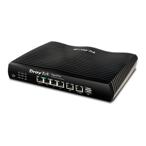
Page 18: I-1-1 Indicators And Connectors
Before you use the Vigor router, please get acquainted with the LED indicators and connectors first. Status Explanation ACT (Activity) Blinking The router is powered on and running normally. The router is powered off. WAN1~WAN2 Internet connection is ready. Internet connection is not ready. Blinking The data is transmitting. - Page 19 Switch on Rear Side (Jack for LTE device) Interface Description Factory Reset Restore the default settings. Usage: Turn on the router (ACT LED is blinking). Press the hole and keep for more than 5 seconds. When you see the ACT LED begins to blink rapidly than usual, release the button. Then the router will restart with the factory default configuration.
-
Page 20: I-1-1-2 For Vigor2926N / Vigor2926Ac / Vigor2926Lac / Vigor2926Ln
Status Explanation ACT (Activity) Blinking The router is powered on and running normally. The router is powered off. WAN1~WAN2 Internet connection is ready. Internet connection is not ready. Blinking The data is transmitting. The QoS function is active. SIM card is connected and running normally. LTE device is not detected or encounters troubles (e.g., No SIM, SIM PIN error, SIM deactivated) Blinking... - Page 21 Blinking The data is transmitting. LED on Connector Left The port is connected. LAN1~ The port is disconnected. LAN4 Blinking The data is transmitting. Right The port is connected with 1000Mbps. The port is connected with 10/100Mbps Left The port is connected. WAN1 The port is disconnected.
- Page 22 Switch on Rear Side (Jack for LTE device) Interface Description Wireless LAN For Vigor2926n: ON/OFF/WPS Press the button and release it within 2 seconds. When the wireless function is ready, the green LED will be on. Press the button and release it within 2 seconds to turn off the WLAN function.
- Page 23 release the button. Then the router will restart with the factory default configuration. LAN1~LAN4 Connecters for local network devices. WAN1~WAN2 Connecter for local network devices or modem for accessing Internet. USB1~2 / USB Connecter for a USB device (for 3G/4G USB Modem or printer or thermometer).
-
Page 24: I-1-1-3 For Vigor2926Vac
Status Explanation ACT (Activity) Blinking The router is powered on and running normally. The router is powered off. WAN1~ Internet connection is ready. WAN2 Internet connection is not ready. Blinking The data is transmitting. Line A PSTN phone call comes (in and out). However, when the phone call is disconnected, the LED will be off. - Page 25 Interface Description Wireless LAN Wireless band will be switched /changed according to the button ON/OFF/WPS pressed and released. For example, 2.4G (On) and 5G (On) – in default. 2.4G (Off) and 5G (On) – pressed and released the button once.
-
Page 26: I-1-2 Notes For Antenna Installation (For "L" Model)
“ ” “ ” Magnetic antenna must be installed on the extension base before connecting to Vigor router. Extension Base There are two mounting holes for installing antennas with extension base on Vigor router. Please install them as shown below. Major Signal Transmitted Hole SIM Card... - Page 27 While installing the SIM card into the card slot, note that back plate of the SIM card slot must be removed first and the direction of card notch must be on the left side. There are two types of antennas provided for Vigor2862Ln/Vigor2862Lac, which must be installed in different locations carefully and correctly.
-
Page 28: Hardware Installation
Before starting to configure the router, you have to connect your devices correctly. In this section, Vigor2926n is taken as an example. Connect the cable Modem/DSL Modem/Media Converter to any WAN port of router with Ethernet cable (RJ-45). Connect one end of an Ethernet cable (RJ-45) to one of the LAN ports of the router and the other end of the cable (RJ-45) into the Ethernet port on your computer. -
Page 29: I-2-2 Wall-Mounted Installation
Vigor router has keyhole type mounting slots on the underside. A template is provided on the Vigor router packaging box to enable you to space the screws correctly on the wall. Place the template on the wall and drill the holes according to the recommended instruction. -
Page 30: I-2-3 Installing Usb Printer To Vigor Router
You can install a printer onto the router for sharing printing. All the PCs connected this router can print documents via the router. The example provided here is made based on Windows 7. For other Windows system, please visit www.DrayTek.com. Before using it, please follow the steps below to configure settings for connected computers (or wireless clients). - Page 31 A dialog will appear. Click Add a local printer and click Next. In this dialog, choose Create a new port. In the field of Type of port, use the drop down list to select Standard TCP/IP Port. Then, click Next. Vigor2926 Series User’s Guide...
- Page 32 In the following dialog, type 192.168.1.1 (router’s LAN IP) in the field of Hostname or IP Address and type 192.168.1.1 as the Port name. Then, click Next. Click Standard and choose Generic Network Card. Vigor2926 Series User’s Guide...
- Page 33 Now, your system will ask you to choose right name of the printer that you installed onto the router. Such step can make correct driver loaded onto your PC. When you finish the selection, click Next. Type a name for the chosen printer. Click Next. Vigor2926 Series User’s Guide...
- Page 34 10. Choose Do not share this printer and click Next. 11. Then, in the following dialog, click Finish. Vigor2926 Series User’s Guide...
- Page 35 12. The new printer has been added and displayed under Printers and Faxes. Click the new printer icon and click Printer server properties. 13. Edit the property of the new printer you have added by clicking Configure Port. Vigor2926 Series User’s Guide...
- Page 36 14. Select "LPR" on Protocol, type p1 (number 1) as Queue Name. Then click OK. Next please refer to the red rectangle for choosing the correct protocol and LPR name. The printer can be used for printing now. Most of the printers with different manufacturers are compatible with vigor router.
-
Page 37: Accessing Web Page
Make sure your PC connects to the router correctly. You may either simply set up your computer to get IP dynamically from the router or set up the IP address of the computer to be the same subnet as the default IP address of Vigor router 192.168.1.1. - Page 38 Now, the Main Screen will appear. Take Vigor2926ac as as example. Info The home page will be different slightly in accordance with the type of the router you have. The web page can be logged out according to the chosen condition. The default setting is Auto Logout, which means the web configuration system will logout after 5 minutes without any operation.
-
Page 39: Changing Password
Please change the password for the original security of the router. Open a web browser on your PC and type http://192.168.1.1. A pop-up window will open to ask for username and password. Please type “admin/admin” as Username/Password for accessing into the web user interface with admin mode. -
Page 40: Dashboard
Dashboard shows the connection status including System Information, IPv4 Internet Access, IPv6 Internet Access, Interface (physical connection), Security and Quick Access. Click Dashboard from the main menu on the left side of the main page. A web page with default selections will be displayed on the screen. Refer to the following figure: Vigor2926 Series User’s Guide... -
Page 41: I-5-1 Virtual Panel
On the top of the Dashboard, a virtual panel (simulating the physical panel of the router) displays the physical interface connection. It will be refreshed every five seconds. When you move and click the mouse cursor on LEDs (except ACT), USB ports, WAN2, or LAN1 – LAN4, related web setting page will be open for you to configure if required. -
Page 42: I-5-3 Status For Lte
It is a short table which displays current status for Vigor2926L/Vigor2926Ln including acess mode used, access tech adopted, band usage, operator, strength of signal and notification of new SMS received. All the menu items can be accessed and arranged orderly on the left side of the main page for your request. -
Page 43: I-5-5 Gui Map
Note that there is a plus ( ) icon located on the left side of LAN/WLAN/VPN/MyVigor. Click it to review the LAN/WLAN/VPN/MyVigor connection(s) used presently. Host connected physically to the router via LAN port(s) will be displayed with green circles in the field of Connected. -
Page 44: I-5-6 Web Console
It is not necessary to use the telnet command via DOS prompt. The changes made by using web console have the same effects as modified through web user interface. The functions/settings modified under Web Console also can be reviewed on the web user interface. -
Page 45: I-5-7 Config Backup
There is one way to store current used settings quickly by clicking the Config Backup icon. It allows you to backup current settings as a file. Such configuration file can be restored by using System Maintenance>>Configuration Backup. Simply click the icon on the top of the main screen and a pop up dialog will appear. Click Save to store the setting. -
Page 46: I-5-9 Online Status
Such page displays the physical connection status such as LAN connection status, WAN connection status, ADSL information, and so on. Vigor2926 Series User’s Guide... - Page 47 Detailed explanation (for IPv4) is shown below: Item Description LAN Status Primary DNS-Displays the primary DNS server address for WAN interface. Secondary DNS -Displays the secondary DNS server address for WAN interface. IP Address-Displays the IP address of the LAN interface. TX Packets-Displays the total transmitted packets at the LAN interface.
-
Page 48: I-5-9-2 Virtual Wan
Item Description TX Packets - Displays the total transmitted packets at the WAN interface. TX Rate - Displays the speed of transmitted octets at the WAN interface. RX Packets - Displays the total number of received packets at the WAN interface. RX Rate - Displays the speed of received octets at the WAN interface. -
Page 49: Quick Start Wizard
Quick Start Wizard can help you to deploy and use the router easily and quickly. Go to Wizards>>Quick Start Wizard. The first screen of Quick Start Wizard is entering login password. After typing the password, please click Next. On the next page as shown below, please select the WAN interface that you use. If Ethernet interface is used, please choose WAN1/WAN2;... -
Page 50: I-6-1 For Wan1/Wan2 (Ethernet)
WAN1/WAN2 is dedicated to physical mode in Ethernet. If you choose WAN1/WAN2, please specify physical type. Then, click Next. On the next page as shown below, please select the appropriate Internet access type according to the information from your ISP. For example, you should select PPPoE mode if the ISP provides you PPPoE interface. - Page 51 Click PPPoE as the Internet Access Type. Then click Next to continue. Available settings are explained as follows: Item Description Service Name Enter the description of the specific network service. (Optional) Username Assign a specific valid user name provided by the ISP. Note: The maximum length of the user name you can set is 63 characters.
- Page 52 Please manually enter the Username/Password provided by your ISP. Click Next for viewing summary of such connection. Click Finish. A page of Quick Start Wizard Setup OK!!! will appear. Then, the system status of this protocol will be shown. Now, you can enjoy surfing on the Internet. Vigor2926 Series User’s Guide...
- Page 53 Choose WAN1/WAN2 as the WAN Interface and click the Next button. The following page will be open for you to specify Internet Access Type. Click PPTP/L2TP as the Internet Access Type. Then click Next to continue. Available settings are explained as follows: Item Description Username...
- Page 54 Specify an IP address – you have to type relational settings manually. IP Address - Type the IP address. Subnet Mask –Type the subnet mask. Gateway – Type the IP address of the gateway. PPTP Server / L2TP Type the IP address of the server. Server Back Click it to return to previous setting page.
- Page 55 Choose WAN1/WAN2 as the WAN Interface and click the Next button. The following page will be open for you to specify Internet Access Type. Click Static IP as the Internet Access type. Simply click Next to continue. Available settings are explained as follows: Item Description WAN IP...
- Page 56 Cancel Click it to give up the quick start wizard. Please type in the IP address information originally provided by your ISP. Then click Next for next step. Click Finish. A page of Quick Start Wizard Setup OK!!! will appear. Then, the system status of this protocol will be shown.
- Page 57 Available settings are explained as follows: Item Description Host Name Type the name of the host. Note: The maximum length of the host name you can set is 39 characters. Some Cable service providers specify a specific MAC address for access authentication. In such cases you need to enter the MAC address.
-
Page 58: I-6-2 For Wan3/Wan4 (Usb)
Click Finish. A page of Quick Start Wizard Setup OK!!! will appear. Then, the system status of this protocol will be shown. Now, you can enjoy surfing on the Internet. WAN3/WAN4 is dedicated to physical mode in USB. Choose WAN3/WAN4 as WAN Interface. Then, click Next for getting the following page. - Page 59 3G/4G USB Modem SIM Pin code –Type PIN code of the SIM card that will be used (PPP mode) to access Internet. The maximum length of the pin code you can set is 15 characters. Modem Initial String – Such value is used to initialize USB modem.
-
Page 60: I-6-3 For Lte Wan
Choose LTE as WAN Interface. Then, click Next for getting the following page. Available settings are explained as follows: Item Description Internet Access Now, DHCP mode is the only choice for LTE WAN. 3G/4G USB Modem SIM Pin code – Type PIN code of the SIM card that will be (DHCP mode) used to access Internet. - Page 61 Please type in required information originally provided by your ISP. Then, click Next for viewing summary of such connection. Click Finish. A page of Quick Start Wizard Setup OK!!! will appear. Then, the system status of this protocol will be shown. Now, you can enjoy surfing on the Internet.
-
Page 62: Service Activation Wizard
Service Activation Wizard is a tool which allows you to use trial version of WCF directly without accessing into the server (MyVigor) located on http://myvigor.draytek.com. For using Web Content Filter Profile, please refer to later section Web Content Filter Profile for detailed information. - Page 63 Cryan 30-day trial is WCF which offers 30-day trial period. After trial, you can purchase DrayTek's prepared Cryan GlobalView WCF package from retailing outlets. DT-APPE, developed by DrayTek, offers a mechanism to upgrade APPE signature automatically. Setting confirmation page will be displayed as follows, please click Activate.
-
Page 64: Registering Vigor Router
You have finished the configuration of Quick Start Wizard and you can surf the Internet at any time. Now it is the time to register your Vigor router to MyVigor website for getting more service. Please follow the steps below to finish the router registration. Please login the web configuration interface of Vigor router by typing “admin/admin”... - Page 65 Info If you haven’t an accessing account, please refer to section Creating an Account for MyVigor to create your own one. Please read the articles on the Agreement regarding user rights carefully while creating a user account. The following page will be displayed after you logging in MyVigor. When the following page appears, please type in Nickname (for the router) and choose the right registration date from the popup calendar (it appears when you click on the box of Registration Date).
- Page 66 This page is left blank. Vigor2926 Series User’s Guide...
-
Page 67: Part Ii Connectivity
It means wide area network. Public IP will be used in WAN. It means local area network. Private IP will be used in LAN. Local Area Network (LAN) is a group of subnets regulated and ruled by router. The design of network structure is related to what type of public IP addresses coming from your ISP. -
Page 68: Wan
It allows users to access Internet. IP means Internet Protocol. Every device in an IP-based Network including routers, print server, and host PCs, needs an IP address to identify its location on the network. To avoid address conflicts, IP addresses are publicly registered with the Network Information Centre (NIC). - Page 69 Besides, 3G/4G USB Modem in WAN3 also can be used as backup device. Therefore, when WAN1 and WAN2 are not available, the router will use 3.5G for supporting automatically. The supported 3G/4G USB Modem will be listed on DrayTek web site. Please visit www.draytek.com for more detailed information.
-
Page 70: Web User Interface
LTE) and WAN4 settings. This webpage allows you to set general setup for WAN1, WAN2, WAN3 (or LTE) and WAN4 respectively. For all of the routers except for Vigor2926L and Vigor2926Ln--- For Vigor2926L and Vigor2926Ln---- Available settings are explained as follows:... -
Page 71: Ii-1-1-1 Wan1/Wan2 With Ethernet
bandwidth for your WAN interface, please choose the setting of According to Line Speed. Otherwise, please choose Auto Weight to let the router reach the best load balance. IP Based - The same source / destination IP pair will select the same WAN interface as policy. - Page 72 Available settings are explained as follows: Item Description Enable Choose Yes to invoke the settings for this WAN interface. Choose No to disable the settings for this WAN interface. Display Name Type the description for such WAN interface. Physical Mode Display the physical mode of such WAN interface.
- Page 73 connection status. Failover – Choose it to make the WAN connection as a backup connection. WAN Failure – When the active WAN failed, such WAN will be activated as the main network connection. Traffic Threshold – When the data traffic of active WAN reaches the traffic threshold (specified here), the failover WAN will be enabled automatically to share the overloaded data traffic.
-
Page 74: Ii-1-1-2 Wan3/Wan4 (Usb)
To use 3G/4G network connection through 3G/4G USB Modem, please configure WAN3 or WAN4 interface. Available settings are explained as follows: Item Description Enable Choose Yes to invoke the settings for this WAN interface. Choose No to disable the settings for this WAN interface. Display Name Type the description for such WAN interface. - Page 75 Active Mode Choose Always On to make the WAN2 connection being activated always. Load Balance: Check this box to enable auto load balance function for such WAN interface. When the data traffic is large, the WAN interface with the function enabled will balance the data transmission automatically among all of the WAN interfaces in connection status.
-
Page 76: Ii-1-2 Internet Access
For the router supports multi-WAN function, the users can set different WAN settings (for WAN1/WAN2/WAN3 or LTE/WAN4) for Internet Access. Due to different Physical Mode for WAN interface, the Access Mode for these connections also varies. Refer to the following figures for examples. - Page 77 Available settings are explained as follows: Item Description Index Display the WAN interface. Display Name It shows the name of the WAN1/WAN2/WAN3 or LTE/WAN4 that entered in general setup. Physical Mode It shows the physical connection for WAN1/WAN2 (Ethernet) /WAN3 or LTE /WAN4 (USB) according to the real network connection.
-
Page 78: Ii-1-2-1 Details Page For Pppoe In Wan1/Wan2 (Physical Mode: Ethernet)
Note If you choose to configure option 61 here, the detailed settings in WAN>>Interface Access will be overwritten. DataType – Choose the type (ASCII or Hex) for the data to be stored. Data – Type the content of the data to be processed by the function of DHCP option. - Page 79 specific network service. Username – Type in the username provided by ISP in this field. The maximum length of the user name you can set is 63 characters. Password – Type in the password provided by ISP in this field. The maximum length of the password you can set is 62 characters.
- Page 80 Path MTU to – Type the IP address as the specific transmit path. MTU reduce size by – It determines the decreasing size of MTU value. For example, the number specified in this field is “8”. The maximum MTU size is “1500”. After clicking the “detect”...
-
Page 81: Ii-1-2-2 Details Page For Static Or Dynamic Ip In Wan1/Wan2 (Physical Mode: Ethernet)
For static IP mode, you usually receive a fixed public IP address or a public subnet, namely multiple public IP addresses from your DSL or Cable ISP service providers. In most cases, a Cable service provider will offer a fixed public IP, while a DSL service provider will offer a public subnet. - Page 82 PING Interval - Enter the interval for the system to execute the PING operation. WAN Connection Such function allows you to verify whether network Detection connection is alive or not through ARP Detect or Ping Detect. Mode – Choose ARP Detect, Ping Detect or Always On for the system to execute for WAN detection.
- Page 83 enabled. When both Bridge Mode and Firewall check boxes are enabled, the settings configured (user profiles) under User Management will be ignored. And all of the filter rules defined and enabled in Firewall menu will be activated. Bridge Subnet – Make a bridge between the selected LAN subnet and such WAN interface.
-
Page 84: Ii-1-2-3 Details Page For Pptp/L2Tp In Wan1/Wan2 (Physical Mode: Ethernet)
After finishing all the settings here, please click OK to activate them. To use PPTP/L2TP as the accessing protocol of the internet, please click the PPTP/L2TP tab. The following web page will be shown. Available settings are explained as follows: Item Description PPTP/L2TP... - Page 85 Path MTU to – Type the IP address as the specific transmit path. MTU reduce size by– It determines the decreasing size of MTU value. For example, the number specified in this field is “8”. The maximum MTU size is “1500”. After clicking the “detect”...
-
Page 86: Ii-1-2-4 Details Page For 3G/4G Usb Modem (Ppp Mode) In Wan3/Wan4
To use 3G/4G USB Modem (PPP mode) as the accessing protocol of the internet, please choose Internet Access from WAN menu. Then, select 3G/4G USB Modem (PPP mode) for WAN3. The following web page will be shown. Available settings are explained as follows: Item Description Modem Support List... - Page 87 SIM PIN code Type PIN code of the SIM card that will be used to access Internet. The maximum length of the PIN code you can set is 15 characters. Modem Initial String Such value is used to initialize USB modem. Please use the default value.
-
Page 88: Ii-1-2-5 Details Page For 3G/4G Usb Modem (Dhcp Mode) In Wan3/Wan4
allowed to execute the PING operation before WAN disconnection is judged. After finishing all the settings here, please click OK to activate them. To use 3G/4G USB Modem (DHCP mode) as the accessing protocol of the internet, please choose Internet Access from WAN menu. Then, select 3G/4G USB Modem (DHCP mode) for WAN3/WAN4. - Page 89 characters. Network Mode Force Vigor router to connect Internet with the mode specified here. If you choose 4G/3G/2G as network mode, the router will choose a suitable one according to the actual wireless signal automatically. APN Name APN means Access Point Name which is provided and required by some ISPs.
-
Page 90: Ii-1-2-6 Details Page For 3G/4G Usb Modem (Dhcp Mode) In Lte Wan
Accept – After clicking it, the detected value will be displayed in the field of MTU. Authentication Select PAP only or PAP or CHAP for PPP authentication. Username – Type the username for authentication (optional). Password – Type the password for authentication (optional). After finishing all the settings here, please click OK to activate them. - Page 91 required by some ISPs. Type the name and click Apply. The maximum length of the name you can set is 47 characters. UserName Type the username (optional). The maximum length of the name you can set is 47 characters. Password Type the password (optional).
-
Page 92: Ii-1-2-7 Details Page For Ipv6 - Offline In Wan1/Wan2/Wan3/Wan4
Ping Retry – Type the number of times that the system is allowed to execute the PING operation before WAN disconnection is judged. After finishing all the settings here, please click OK to activate them. – – When Offline is selected, the IPv6 connection will be disabled. –... -
Page 93: Ii-1-2-9 Details Page For Ipv6 - Tspc In Wan1/Wan2/Wan3/Wan4
Detection connection is alive or not through Ping Detect. Mode – Choose Always On or Ping Detect for the system to execute for WAN detection. Always On means no detection will be executed. The network connection will be on always. ... - Page 94 Available settings are explained as follows: Item Description Username Type the name obtained from the broker. It is suggested for you to apply another username and password for http://gogonet.gogo6.com/page/freenet6-account. The maximum length of the name you can set is 63 characters.
-
Page 95: Ii-1-2-10 Details Page For Ipv6 - Aiccu In Wan1/Wan2/Wan3/Wan4
– – Available settings are explained as follows: Item Description Always On Check this box to keep the network connection always. Username Type the name obtained from the broker. Please apply new account at http://www.sixxs.net/. It is suggested for you to apply another username and password. - Page 96 WAN Connection Such function allows you to verify whether network Detection connection is alive or not through Ping Detect. Mode – Choose Always On or Ping Detect for the system to execute for WAN detection. Ping IP/Hostname – If you choose Ping Detect as detection mode, you have to type IP address in this field for pinging.
-
Page 97: Ii-1-2-11 Details Page For Ipv6 - Dhcpv6 Client In Wan1/Wan2
– – DHCPv6 client mode would use DHCPv6 protocol to obtain IPv6 address from server. Available settings are explained as follows: Item Description IAID Type a number as IAID. WAN Connection Such function allows you to verify whether network Detection connection is alive or not through NS Detect or Ping Detect. -
Page 98: Ii-1-2-12 Details Page For Ipv6 - Static Ipv6 In Wan1/Wan2
– – This type allows you to setup static IPv6 address for WAN interface. Available settings are explained as follows: Item Description Static IPv6 Address IPv6 Address – Type the IPv6 Static IP Address. configuration Prefix Length – Type the fixed value for prefix length. Add –... - Page 99 Ping IP/Hostname – If you choose Ping Detect as detection mode, you have to type IP address in this field for pinging. TTL (Time to Live) –If you choose Ping Detect as detection mode, you have to type TTL value. Bridge Mode Enable Bridge Mode - If the function is enabled, the router will work as a bridge modem.
-
Page 100: Ii-1-2-13 Details Page For Ipv6 - 6In4 Static Tunnel In Wan1/Wan2
– – This type allows you to setup 6in4 Static Tunnel for WAN interface. Such mode allows the router to access IPv6 network through IPv4 network. However, 6in4 offers a prefix outside of 2002::0/16. So, you can use a fixed endpoint rather than anycast endpoint. -
Page 101: Ii-1-2-14 Details Page For Ipv6 - 6Rd In Wan1/Wan2
Below shows an example for successful IPv6 connection based on 6in4 Static Tunnel mode. – – This type allows you to setup 6rd for WAN interface. Available settings are explained as follows: Item Description 6rd Mode Auto 6rd – Retrieve 6rd prefix automatically from 6rd service provider. - Page 102 IPv4 Border Relay Type the IPv4 addresses of the 6rd Border Relay for a given 6rd domain. IPv4 Mask Length Type a number of high-order bits that are identical across all CE IPv4 addresses within a given 6rd domain. It may be any value between 0 and 32. 6rd Prefix Type the 6rd IPv6 address.
-
Page 103: Ii-1-3 Multi-Vlan
Multi-VLAN allows users to create profiles for specific WAN interface and bridge connections for user applications that require very high network throughput. Simply go to WAN and select Multi-VLAN. This page shows the basic configurations used by every channel. Available settings are explained as follows: Item Description Channel... - Page 104 Click any index (8, 9 and 10) to get the following web page: Available settings are explained as follows: Item Description Multi-VLAN Channel Enable – Click it to enable the configuration of this channel. 8/9/10 Disable –Click it to disable the configuration of this channel. WAN Type The connections and interfaces created in every channel may select a specific WAN type to be built upon.
- Page 105 WAN links for Channel 5, 6 and 7 are provided for router-borne application such as TR-069. The settings must be applied and obtained from your ISP. For your special request, please contact with your ISP and then click WAN link of Channel 5, 6 or 7 to configure your router. Available settings are explained as follows: Item Description...
- Page 106 General Settings VLAN Tag – Type the value as the VLAN ID number. Valid settings are in the range from 1 to 4095. The network traffic flowing on each channel will be identified by the system via their VLAN Tags. Channels using the same WAN type may not configure the same VLAN tag value.
-
Page 107: Ii-1-4 Wan Budget
This function is used to determine the data traffic volume for each WAN interface respectively to prevent from overcharges for data transmission by the ISP. Please note that the Quota Limit and Billing cycle day of month settings will need to be configured correctly first in order for some period calculations to be performed correctly. - Page 108 Item Description Enable Check the box to enable such function. Quota Limit Type the data traffic quota allowed for such WAN interface. There are two unit (MB and GB) offered for you to specify. When quota exceeded Check the box(es) as the condition(s) for the system to perform when the traffic has exceeded the budget limit.
-
Page 109: Ii-1-4-2 Status
status page displays the status WAN budget, including the duration and the usage. If the WAN budget is exhausted, a lock will be displayed on the page if Shutdown WAN interface is selected. Which means no data transmission will be carried out. Moreover, the system will send out a warning message to the administrator if Mail Alert is selected. -
Page 110: Application Notes
Due to the shortage of IPv4 address, more and more countries use IPv6 to solve the problem. However, to continually use the original rich resources of IPv4, both IPv6 and IPv4 networks shall communicate for each other via intercommunication mechanism to complete the shifting job from IPv4 to IPv6 gradually. - Page 111 In the following figure, use the drop down list to choose a proper connection type. Different connection types will bring out different configuration page. Refer to the following: PPP – Dual Stack application, IPv4 and IPv6 services can be utilized at the same time Choose PPP and type the information for PPPoE of IPv4.
- Page 112 Vigor2926 Series User’s Guide...
- Page 113 TSPC – Tunnel application, both IPv6 hosts communicate through IPv4 network Choose TSPC and type the information for TSPC service. Info While using such mode, you have to make sure the IPv4 network connection is normal. (In the following figure, the TSPC information is obtained from http://gogo6.com/ after applied for the service.) Click OK and open Online Status.
- Page 114 AICCU – Tunnel application Choose AICCU and type the information for AICCU of IPv6. Info While using such mode, you have to make sure the IPv4 network connection is normal. (In the following figure, the AICCU information is obtained from https://www.sixxs.net/main/ after applied for the service.) Click OK and open Online Status.
- Page 115 DHCPv6 Client Choose DHCPv6 Client. Click one of the identity associations and type the IAID number. Click OK and open Online Status. If the connection is successful, the physical connection will be shows as follows: Vigor2926 Series User’s Guide...
- Page 116 Static IPv6 Choose Static IPv6. Type IPv6 address, Prefix Length and Gateway Address. Click OK and open Online Status. If the connection is successful, the physical connection will be shows as follows: Vigor2926 Series User’s Guide...
- Page 117 6in4 Static Tunnel Choose 6in4 Static Tunnel. Type remote endpoint IPv4 address, 6in4 IPv6 Address, LAN Routed Prefix and Tunnel TTL. Click OK and open Online Status. If the connection is successful, the physical connection will be shows as follows: Vigor2926 Series User’s Guide...
- Page 118 Choose 6rd. Type IPv4 Border Relay, IPv4 Mask Length, 6rd Prefix and 6rd Prefix Length. Click OK and open Online Status. If the connection is successful, the physical connection will be shows as follows: Vigor2926 Series User’s Guide...
- Page 119 After finished the WAN settings for IPv6, please configure the LAN settings to make the router’s client get the IPv6 address. Access into the web user interface of Viogr2860. Open LAN>> General Setup. Click the IPv6 button. Info Only the subnet of LAN1 supports IPv6 feature. In the field of RADVD Configuration, the default setting is Enable.
- Page 120 Make sure you have obtained the correct IPv6 IP address. Get into MS-DOS interface and type the command of “ipconfig”. Refer to the following figure. From the above figure we can see IPv6 IP address has been captured by the system. Use the Ping command to ping any IPv6 address indicating an IPv6 website.
- Page 121 Connect to the website for IPv6. Open a web browser and type an URL of IPv6, e.g., www.kame.net. If your computer accesses into the website by using IPv6 address, you may see a turtle dancing on the screen. If not, only a steady turtle will be seen. If you can see a turtle dancing on the screen, that means IPv6 service is ready for you to access and utilize.
-
Page 122: Lan
Local Area Network (LAN) is a group of subnets regulated and ruled by router. The design of network structure is related to what type of public IP addresses coming from your ISP. The most generic function of Vigor router is NAT. It creates a private subnet of your own. As mentioned previously, the router will talk to other public hosts on the Internet by using public IP address and talking to local hosts by using its private IP address. - Page 123 Vigor router will exchange routing information with neighboring routers using the RIP to accomplish IP routing. This allows users to change the information of the router such as IP address and the routers will automatically inform for each other. When you have several subnets in your LAN, sometimes a more effective and quicker way for connection is the Static routes function rather than other method.
-
Page 124: Web User Interface
This page provides you the general settings for LAN. Click LAN to open the LAN settings page and choose General Setup. There are four subnets provided by the router which allow users to divide groups into different subnets (LAN1 – LAN5). In addition, different subnets can link for each other by configuring Inter-LAN Routing. - Page 125 LAN2 –LAN5 and IP Routed Subnet can be observed by checking the box of Status. DHCP- LAN1 is configured with DHCP in default. If required, please check the DHCP box for each LAN. IP Address - Display the IP address for each LAN item. Such information is set in default and you can not modify it.
-
Page 126: Ii-2-1-1 Details Page For Lan1 - Ethernet Tcp/Ip And Dhcp Setup
– – There are two configuration pages for LAN1, Ethernet TCP/IP and DHCP Setup (based on IPv4) and IPv6 Setup. Click the tab for each type and refer to the following explanations for detailed information. Available settings are explained as follows: Item Description Network Configuration... - Page 127 Relay Agent is checked. Set the IP address of the DHCP server you are going to use so the Relay Agent can help to forward the DHCP request to the DHCP server. Start IP Address - Enter a value of the IP address pool for the DHCP server to start with when issuing IP addresses.
-
Page 128: Ii-2-1-2 Details Page For Lan2 ~ Lan5 And Dmz
connection. When you finish the configuration, please click OK to save and exit this page. Available settings are explained as follows: Item Description Network Configuration Enable/Disable - Click Enable to enable such configuration; click Disable to disable such configuration. For NAT Usage - Click this radio button to invoke NAT function. - Page 129 DHCP request to the DHCP server. Start IP Address - Enter a value of the IP address pool for the DHCP server to start with when issuing IP addresses. If the 1st IP address of your router is 192.168.1.1, the starting IP address must be 192.168.1.2 or greater, but smaller than 192.168.1.254.
-
Page 130: Ii-2-1-3 Details Page For Ip Routed Subnet
When you finish the configuration, please click OK to save and exit this page. Available settings are explained as follows: Item Description Network Configuration Enable/Disable - Click Enable to enable such configuration; click Disable to disable such configuration. For Routing Usage, IP Address - Type in private IP address for connecting to a local private network (Default: 192.168.1.1). -
Page 131: Ii-2-1-4 Details Page For Lan Ipv6 Setup
IP Pool Counts - Enter the maximum number of PCs that you want the DHCP server to assign IP addresses to. The default is 50 and the maximum is 253. Lease Time - Enter the time to determine how long the IP address assigned by DHCP server can be used. - Page 132 It provides 2 daemons for LAN side IPv6 address configuration. One is SLAAC(stateless) and the other is DHCPv6 (Stateful) server. Available settings are explained as follows: Item Description Enable IPv6 Check the box to enable the configuration of LAN 1 IPv6 Setup.
- Page 133 Auto ULA Prefix – The system will generate the required IPv6 address. Manually ULA Prefix – A user can type the ULA IPv6 address manually. Current IPv6 Address Display current used IPv6 addresses. Table DNS Server IPv6 Address Deploy when WAN is up – When it is enabled, DNS query will not be delivered until the selected IPv6 WAN interface is up.
- Page 134 Advance setting More options are offered under the Advance setting. Click Edit to open the pop-up window. Router Advertisement Configuration – Click Enable to enable router advertisement server. The router advertisement daemon sends Router Advertisement messages, specified by RFC 2461, to a local Ethernet LAN periodically and when requested by a node sending a Router Solicitation message.
- Page 135 from the primary WAN, but also the prefix for IPv6 LAN IP address can be assigned by extension WAN specified here. When you finish the configuration, please click OK to save and exit this page. Vigor2926 Series User’s Guide...
-
Page 136: Application Notes
1. Open LAN>>General Setup. Click the Details Page button of LAN1. 2. In the setting page, type the settings as follows and click OK to save the settings. Note that LAN1 is always for NAT usage. Vigor2926 Series User’s Guide... - Page 137 3. In the setting page, type the settings as follows and click OK to save the settings. Note that LAN1 is always for NAT usage. 4. Return to LAN>>General Setup. Now, LAN2 is available for configuration. Click the Details Page button of LAN2. Choose For Routing Usage. Type the settings as follows and click OK to save the settings.
- Page 138 7. Now, a network connection via MPLS (Multiprotocol Label Switching) between LAN2 user and the Branch user is established successfully. Internet is not required for them. Vigor2926 Series User’s Guide...
-
Page 139: Ii-2-2 Vlan
With the 6-port Gigabit switch on the LAN side, Vigor router provides extremely high speed connectivity for the highest speed local data transfer of any server or local PCs. On the Wireless-equipped models (e.g., Vigor2926n), each of the wireless SSIDs can also be grouped within one of the VLANs. - Page 140 For Vigor router with 2.4GHz and 5GHz features, the web page will be shown as follow: Info Settings in this page only applied to LAN port but not WAN port. Available settings are explained as follows: Item Description Enable Click it to enable VLAN configuration. P1 –...
- Page 141 VLAN Tag Enable – Check the box to enable the function of VLAN with tag. The router will add specific VLAN number to all packets on the LAN while sending them out. Please type the tag value and specify the priority for the packets sending by LAN.
- Page 142 Vigor router supports up to six private IP subnets on LAN. Each can be independent (isolated) or common (able to communicate with each other). This is ideal for departmental or multi-occupancy applications. Info As for the VLAN applications, refer to “Appendix I: VLAN Application on Vigor Router”...
-
Page 143: Ii-2-3 Bind Ip To Mac
This function is used to bind the IP and MAC address in LAN to have a strengthening control in network. When this function is enabled, all the assigned IP and MAC address binding together cannot be changed. If you modified the binding IP or MAC address, it might cause you not access into the Internet. - Page 144 Strict Bind Check it to block the connection of the IP/MAC which is not listed in IP Bind List. Apply Strict Bind to Subnet – Click Edit to shoose the subnet(s) for applying the rules of Bind IP to MAC. ARP Table This table is the LAN ARP table of this router.
-
Page 145: Ii-2-4 Lan Port Mirror
LAN port mirror can be applied for the users in LAN. Generally speaking, this function copies traffic from one or more specific ports to a target port. This mechanism helps manager track the network errors or abnormal packets transmission without interrupting the flow of data access the network. -
Page 146: Ii-2-5 Wired 802.1X
IEEE 802.1x is an IEEE Standard for port-based Network Access Control (PNAC). It is part of the IEEE 802.1 group of networking protocols. It provides an authentication mechanism for the device that is attached to a LAN or WLAN. Wired 802.1x provides authentication for one network device on each LAN port. The RADIUS Server settings must be configured before enabling 802.1x because the EAP (Extensible Authentication Protocol) Authenticator relies on the RADIUS Server in its authentication process. -
Page 147: Hardware Acceleration
Hardware Acceleration is also called PPA in DrayTek for it is based on Protocol Processing Engine (PPE) of Infineon. It can only support 128 sessions for network traffic (IN & OUT) with implementing three kinds of modes - Disable, Auto and Manual. - Page 148 Protocol There are two types supported by this function, TCP and UDP. Option Accelerate heaviest traffic sessions – Such option is available in Auto Mode, too. But the UDP protocol is only supported in this sub-item. Apply the Class Rule in Quality of Service – Users can apply the information provided by QoS in this sub-item.
- Page 149 Vigor2926 Series User’s Guide...
-
Page 150: Nat
Usually, the router serves as an NAT (Network Address Translation) router. NAT is a mechanism that one or more private IP addresses can be mapped into a single public one. Public IP address is usually assigned by your ISP, for which you may get charged. Private IP addresses are recognized only among internal hosts. -
Page 151: Web User Interface
Port Redirection is usually set up for server related service inside the local network (LAN), such as web servers, FTP servers, E-mail servers etc. Most of the case, you need a public IP address for each server and this public IP address/domain name are recognized by all users. Since the server is actually located inside the LAN, the network well protected by NAT of the router, and identified by its private IP address/port, the goal of Port Redirection function is to forward all access request with public IP address from external users to the mapping... - Page 152 Each item is explained as follows: Item Description Index Display the number of the profile. Service Name Display the description of the specific network service. WAN Interface Display the WAN IP address used by the profile. Protocol Display the transport layer protocol (TCP or UDP). Public Port Display the port number which will be redirected to the specified Private IP and Port of the internal host.
- Page 153 Enable Check this box to enable such port redirection setting. Mode Two options (Single and Range) are provided here for you to choose. To set a range for the specific service, select Range. In Range mode, if the public port (start port and end port) and the starting IP of private IP had been entered, the system will calculate and display the ending IP of private IP automatically.
- Page 154 Vigor2926 Series User’s Guide...
-
Page 155: Ii-4-2 Dmz Host
As mentioned above, Port Redirection can redirect incoming TCP/UDP or other traffic on particular ports to the specific private IP address/port of host in the LAN. However, other IP protocols, for example Protocols 50 (ESP) and 51 (AH), do not travel on a fixed port. Vigor router provides a facility DMZ Host that maps ALL unsolicited data on any protocol to a single host in the LAN. - Page 156 Available settings are explained as follows: Item Description WAN1 Choose Private IP or None first. Private IP Enter the private IP address of the DMZ host, or click Choose PC to select one. Choose IP Click this button and then a window will automatically pop up, as depicted below.
- Page 157 Available settings are explained as follows: Item Description Enable Check to enable the DMZ Host function. Private IP Enter the private IP address of the DMZ host, or click Choose IP to select one. Choose IP Click this button and then a window will automatically pop up, as depicted below.
-
Page 158: Ii-4-3 Open Ports
Open Ports allows you to open a range of ports for the traffic of special applications. Common application of Open Ports includes P2P application (e.g., BT, KaZaA, Gnutella, WinMX, eMule and others), Internet Camera etc. Ensure that you keep the application involved up-to-date to avoid falling victim to any security exploits. - Page 159 Available settings are explained as follows: Item Description Enable Open Ports Check to enable this entry. Comment Make a name for the defined network application/service. WAN Interface Specify the WAN interface that will be used for this entry. Source IP Use the drop down list to specify an IP object.
-
Page 160: Ii-4-4 Port Triggering
After finishing all the settings here, please click OK to save the configuration. Port Triggering is a variation of open ports function. The key difference between "open port" and "port triggering" is: Once the OK button is clicked and the configuration has taken effect, "open port" keeps the ports opened forever. - Page 161 Triggering Protocol Display the protocol of the triggering packets. Triggering Port Display the port of the triggering packets. Source IP Display the name of the IP object. Incoming Protocol Display the protocol for the incoming data of such triggering profile. Incoming Port Display the port for the incoming data of such triggering profile.
-
Page 162: Ii-4-5 Alg
protocol (TCP, UDP or TCP/UDP) for the incoming data of such triggering profile. Incoming Port Type the port or port range for the incoming packets. After finishing all the settings here, please click OK to save the configuration. ALG means Application Layer Gateway. There are two methods provided by Vigor router, RTSP (Real Time Streaming Protocol) ALG and SIP (Session Initiation Protocol) ALG, for processing the packets of voice and video. -
Page 163: Applications
The ISP often provides you with a dynamic IP address when you connect to the Internet via your ISP. It means that the public IP address assigned to your router changes each time you access the Internet. The Dynamic DNS feature lets you assign a domain name to a dynamic WAN IP address. - Page 164 The UPnP (Universal Plug and Play) protocol is supported to bring to network connected devices the ease of installation and configuration which is already available for directly connected PC peripherals with the existing Windows 'Plug and Play' system. For NAT routers, the major feature of UPnP on the router is “NAT Traversal”.
-
Page 165: Web User Interface
Assume you have a registered domain name from the DDNS provider, say hostname.dyndns.org, and an account with username: test and password: test. Open Applications>>Dynamic DNS. In the DDNS setup menu, check Enable Dynamic DNS Setup. Available settings are explained as follows: Item Description Enable Dynamic DNS... - Page 166 Select Index number 1 to add an account for the router. Check Enable Dynamic DNS Account, and choose correct Service Provider: dyndns.org, type the registered hostname: hostname and domain name suffix: dyndns.org in the Domain Name block. The following two blocks should be typed your account Login Name: test and Password: test.
- Page 167 first channel for such account. If WAN1/WAN2/WAN3 or LTE /WAN4 fails, the router will use another WAN interface instead. WAN1/WAN2/WAN3 or LTE /WAN4 Only - While connecting, the router will use WAN1/WAN2/WAN3 or LTE /WAN4 as the only channel for such account. Service Provider Select the service provider for the DDNS account.
- Page 168 Click OK button to activate the settings. You will see your setting has been saved. DrayDDNS, a new DDNS service developed by DrayTek, can record multiple WAN IP (IPv4) on single domain name. It is convenient for users to use and easily to set up. Each Vigor Router is available to register one domain name.
- Page 169 There are two methods offered for you to choose: WAN IP - If it is selected and the WAN IP of Vigor router is private, DDNS update will take place right away. Internet IP – If it is selected and the WAN IP of Vigor router is ...
-
Page 170: Ii-5-2 Lan Dns / Dns Forwarding
The LAN DNS lets the network administrators host servers with privacy and security. When the network administrators of your office set up FTP, Mail or Web server inside LAN, you can specify specific private IP address (es) to correspondent servers. Thus, even the remote PC is adopting public DNS as the DNS server, the LAN DNS resolution on Vigor2926 series will respond the specified private IP address. - Page 171 Profile Display the name of the LAN DNS profile. Domain Name Display the domain name of the LAN DNS profile. Forwarding Display that such profile is conditional DNS forwarding or not. DNS Server Display the IP addres of the DNS Server. You can set up to 20 LAN DNS profiles.
- Page 172 Only use this record…. – Different LAN PCs can share the same domain name. However, you have to check this box to make the router identify & respond the IP address for the DNS query coming from different LAN Delete –...
-
Page 173: Ii-5-3 Dns Security
DNS security is able to ensure that the incoming data is not falsified and the source of the data is secure and correct to prevent from DNS attack by someone. All of WAN interfaces of Vigor router can be configured with DNS Security enabled respectively. -
Page 174: Ii-5-3-2 Domain Diagnose
This page is used to configure settings for manually detecting if the domain is secure not. Available settings are explained as follows: Item Description Domain Type the domain name or IP address (IPv4/IPv6) that you want to query. Interface Specify the interface required for executing diagnose. DNS Server Type the IP address of the DNS Server which will diagnose the domain specified above. -
Page 175: Ii-5-4 Schedule
The Vigor router has a built-in clock which can update itself manually or automatically by means of Network Time Protocols (NTP). As a result, you can not only schedule the router to dialup to the Internet at a specified time, but also restrict Internet access to certain hours so that users can connect to the Internet only during certain hours, say, business hours. - Page 176 Index Click the index number link to access into the setting page of schedule. Comment Display the name of the time schedule. Time Display the valid time period by time bar. Days in a week Display which day(s) will be always on and which day(s) will be always off of the schedule profile by color boxes.
-
Page 177: Ii-5-5 Radius/Tacacs
Action Specify which action should be applied during the period of the schedule. Force On -Force the connection to be always on. Force Down -Force the connection to be always down. How Often Specify how often the schedule will be applied. ... -
Page 178: Ii-5-5-2 Internal Radius
Available settings are explained as follows: Item Description Enable Check to enable RADIUS client feature. Server IP Address Enter the IP address of RADIUS server Destination Port The UDP port number that the RADIUS server is using. The default value is 1812, based on RFC 2138. Shared Secret The RADIUS server and client share a secret that is used to authenticate the messages sent between them. - Page 179 Available settings are explained as follows: Item Description Enable Check to enable internal RADIUS client feature. Authentication Port Set a port number for internal RADIUS server. RADIUS Client Access List Allow to configure that clients under specified domain (IPv4 and IPv6) must be authenticated with the specified shared secret.
-
Page 180: Ii-5-5-3 External Tacacs
secret. The maximum length of the shared secret you can set is 36 characters. IP Address – Type the IP addres of the wired/wireless client. IP Mask – Type the subnet mask required for the IP address. IPv6 Address – Type the IPv6 address of the wired/wireless client. - Page 181 Available settings are explained as follows: Item Description Enable Check to enable TACACS+ feature. Server IP Address Enter the IP address of TACACS+ server. Destination Port The UDP port number that the TACACS+ server is using. Shared Secret The TACACS+ server and client share a secret that is used to authenticate the messages sent between them.
-
Page 182: Ii-5-6 Active Directory/Ldap
Lightweight Directory Access Protocol (LDAP) is a communication protocol for using in TCP/IP network. It defines the methods to access distributing directory server by clients, work on directory and share the information in the directory by clients. The LDAP standard is established by the work team of Internet Engineering Task Force (IETF). -
Page 183: Ii-5-6-2 Profiles
and Regular Password. Server Address Enter the IP address of LDAP server. Destination Port Type a port number as the destination port for LDAP server. Use SSL Check the box to use the port number specified for SSL. Regular DN Type this setting if Regular Mode is selected as Bind Type. - Page 184 Available settings are explained as follows: Item Description Name Type a name for such profile. The length of the user name is limited to 19 characters. Common Name Identifier Type or edit the common name identifier for the LDAP server. The common name identifier for most LDAP server is “cn”.
-
Page 185: Ii-5-7 Upnp
The UPnP (Universal Plug and Play) protocol is supported to bring to network connected devices the ease of installation and configuration which is already available for directly connected PC peripherals with the existing Windows 'Plug and Play' system. For NAT routers, the major feature of UPnP on the router is “NAT Traversal”. -
Page 186: Ii-5-8 Igmp
IGMP is the abbreviation of Internet Group Management Protocol. It is a communication protocol which is mainly used for managing the membership of Internet Protocol multicast groups. Available settings are explained as follows: Item Description IGMP Proxy Check this box to enable this function. The application of multicast will be executed through WAN /PVC/VLAN port. -
Page 187: Ii-5-8-2 Working Groups
IGMP Fast Leave Check this box to make the router stop forwarding multicast traffic to a LAN port as soon as it receives a leave message from that port. Each LAN port should have one IGMP host connected. After finishing all the settings here, please click OK to save the configuration. Available settings are explained as follows: Item Description... -
Page 188: Ii-5-9 Wake On Lan
A PC client on LAN can be woken up by the router it connects. When a user wants to wake up a specified PC through the router, he/she must type correct MAC address of the specified PC on this web page of Wake on LAN (WOL) of this router. In addition, such PC must have installed a network card supporting WOL function. -
Page 189: Ii-5-10 Sms / Mail Alert Service
The function of SMS (Short Message Service)/Mail Alert is that Vigor router sends a message to user’s mobile or e-mail box through specified service provider to assist the user knowing the real-time abnormal situations. Vigor router allows you to set up to 10 SMS profiles which will be sent out according to different conditions. -
Page 190: Ii-5-10-2 Mail Alert
This page allows you to specify Mail Server profile, who will get the notification e-mail, what the content is and when the message will be sent. Available settings are explained as follows: Item Description Index Check the box to enable such profile. Mail Service Use the drop down list to choose mail service object. -
Page 191: Ii-5-11 Bonjour
Bonjour is a service discovery protocol which is a built-in service in Mac OS X; for Windows or Linux platform, there is correspondent software to enable this function for free. Usually, users have to configure the router or personal computers to use above services. Sometimes, the configuration (e.g., IP settings, port number) is complicated and not easy to complete. - Page 192 2. Open the web browse, Firefox. If Bonjour and DNSSD have been installed, you can open the web page (DNSSD) and see the following results. 3. Open System Maintenance>>Management. Type a name as the Router Name and click 4. Next, open Applications>>Bonjour. Check the service that you want to use via Bonjour. 5.
- Page 193 6. Now, any page or document can be printed out through Vigor router (installed with a printer). Vigor2926 Series User’s Guide...
-
Page 194: Ii-5-12 High Availability
(the “primary”) to the backup component (the “secondary”). This process remains system-wide resources, recovers partial of failed transactions, and restores the system to normal within a few seconds. To configure High Availability on, at least two DrayTek routers: Enable High Availability on the Primary and Secondary routers. ... - Page 195 Available settings are explained as follows: Item Description Enable High Abailablity Check this box to enable HA function. Redundancy Method Choose Hot-Standby or Active-Standby as the method for HA. Hot-Standby - Such method is suitable for a user which has one ISP account. With such method;...
-
Page 196: Ii-5-12-2 Config Sync
It is used for encrypting the DARP to prevent malicious attack. Protocol Choose IPv4 or IPv6. Management Interface Such interface is used for DARP (DrayTek Address Redundancy Protocol) negotiation between routers. Only the interface which is enabled in LAN>>General Setup is available for selection. However, LAN1 is always enabled. - Page 197 Available settings are explained as follows: Item Description Enable Config Sync (Max. Check this box to enable configuration synchronization. Sync to 10 routers) To sync configuration from primary to secondary router, both primary and seconday routers need to enable “config sync”.
-
Page 198: Ii-5-13 Local 802.1X General Setup
Such page allows you to configure general settings for Local 802.1X server built in Vigor router. Available settings are explained as follows: Item Description Enable Click it to enable local 802.1X server. At present, such feature can be used for wireless and wired 802.1x authentication. - Page 199 User Profile Select All – Click it to select all of the profiles under Available List. Clear All – Click it to remove all of the profiles under Authentication List. Sync User Profile …. Make the enabling/disabling setting for both Internal RADIUS and Local 802.1X synchronize for all of the user profiles (User Management>>User Profile).
-
Page 200: Application Notes
Vigor router supports various DDNS service providers, user can set up user-defined profile to update the DDNS even the service provider is not on the list. Now, DrayTek starts to support our own DDNS service - DrayDDNS. We will provide a domain name for each Vigor Router, this single domain name can record IP addresses of all WAN. - Page 201 Tick Enable Dynamic DNS Setup b. Click an available profile index c. Tick Enable Dynamic DNS Account d. Select DrayTek Global (www.drayddns.com) as Service Provider e. Select the WAN you would like to upload the IP to DDNS server f. Click Get domain g.
- Page 202 Currently, only the domain name is allowed to be modified MyVigor website. We will need to register the router to MyVigor server, and log in to MyVigor website to modify it. Please visit https://myvigor.draytek.com/ or go to Applications >> Dynamic DNS Setup >> DrayDDNS profile and click Edit domain.
- Page 203 Input the desired Domain name (e.g., XXXX25) and click Update. Vigor router will get the modified domain name when the it performs next DDNS updating. We can click Sync domain to accelerate this process. After few seconds, the router will get the new domain name and print it on the profiles list.
- Page 204 Vigor2926 Series User’s Guide...
-
Page 205: How To Configure Customized Ddns
This article describes how to configure customized DDNS on Vigor routers to update your IP to the DDNS server. We will take “Changeip.org” and “3322.net” as example. Before setting, please make sure that the WAN connection is up. Note that, Username: jo*** Password: jo******** Host name: j*****.changeip.org... - Page 206 Now we have to configure the router so it can do the same job for us automatically. Please go to Applications >> Dynamic DNS to create a profile for Customized DDNS client. Set the Service Provider as Customized. Set the Service API as: /dynamic/dns/update.asp?u=jo***&p=jo********&hostname=j****.changeip.org&ip=###IP ### &cmd=update&offline=0 In which, ###IP### is a value which will be replaced with the current interface IP...
- Page 207 WAN IP address: 111.243.178.53 To update the IP to the DDNS server via editing the HTML script, we can type the following script on the browser: “good 111.243.178.53” means our IP has been updated to the server successfully. Now we have to configure the router so it can do the same job for us automatically. Please go to Applications >>...
- Page 208 The customized Service Provider is also eligible with the ClouDNS.net. Vigor2926 Series User’s Guide...
-
Page 209: How To Implement The Ldap/Ad Authentication For User Management
For simplifying the configuration of LDAP authentication for User Access Management, we implement “Group” feature. There is no need to pre-configure user profile for each user on Vigor router anymore. We only need to configure the Groups DN, then the Vigor router (e.g., Vigor 2925 series) can pass the authentication to LDAP server with the pre-defined Group path. - Page 210 Click OK to save the settings above. Open User Management>>General Setup. Select User-Based as the Mode option. Vigor2926 Series User’s Guide...
- Page 211 Then open VPN and Remote Access>>PPP General Setup to check the profile(s) that will be authenticated with LDAP server. After above configurations, users belong to either “rd1” or “shrd” group can access Internet after inputting their credentials on LDAP server. Vigor2926 Series User’s Guide...
-
Page 212: Routing
Other routing Specify routing policy to determine the direction of the data transmission. Info For more detailed information about using policy route, refer to Support >>FAQ/Application Notes on www.draytek.com. Vigor2926 Series User’s Guide... -
Page 213: Web User Interface
Static routing is an alternative to dynamic routing. It is a process that the system network administrator can configure network routers with all the required information for packet forwarding. Go to LAN >> Static Route. The router offers IPv4 and IPv6 for you to configure the static route. - Page 214 Here is an example (based on IPv4) of setting Static Route in Main Router so that user A and B locating in different subnet can talk to each other via the router. Assuming the Internet access has been configured and the router works properly: use the Main Router to surf the Internet.
- Page 215 Click the LAN >> Static Route and click on the Index Number 1. Check the Enable box. Please add a static route as shown below, which regulates all packets destined to 192.168.10.0 will be forwarded to 192.168.1.2. Click OK. Available settings are explained as follows: Item Description Enable...
- Page 216 You can set up to 40 profiles for IPv6 static route. Click the IPv6 tab to open the following page: Available settings are explained as follows: Item Description Index The number (1 to 40) under Index allows you to open next page to set up static route.
- Page 217 Network Interface Use the drop down list to specify an interface for this static route. When you finish the configuration, please click OK to save and exit this page. Vigor2926 Series User’s Guide...
-
Page 218: Ii-6-2 Load-Balance /Route Policy
Available settings are explained as follows: Item Description Index Click the number of index to access into the configuration web page. Enable Check this box to enable this policy. Protocol Display the protocol used for this policy. Interface Display the interface to send packets to once the policy is matched. - Page 219 2. Click Index 1. The setting page will appear as follows: Available settings are explained as follows: Item Description Source IP Any – Any IP can be treated as the source IP. Src IP Start - Type the source IP start for the specified WAN interface.
- Page 220 4. After specifying the interface, click Next to get the following page. Available settings are explained as follows: Item Description Force NAT /Force It determines which mechanism that the router will use to Routing forward the packet to WAN. 5. After choosing the mechanism, click Next to get the summary page for reference. 6.
- Page 221 To use Advance Mode, do the following steps: 1. Click the Advance Mode radio button. 2. Click any Index number link (e.g., 1 in this case) to access into the following page. Available settings are explained as follows: Item Description Enable Check this box to enable this policy.
- Page 222 Mask – Use the drop down list to choose a suitable mask for the network. IP Object / IP Group– Use the drop down list to choose a preconfigured IP object/group. Destination Any – Any IP can be treated as the destination IP. IP Range –...
-
Page 223: Ii-6-2-2 Diagnose
Route Policy – Use the drop down list to choose an existed route policy profile. Gateway IP – Specific gateway is used only when you want to forward the packets to the desired gateway. Usually, Default Gateway is selected in default. Priority Packets will be transmitted based on all routes or Route Policy. - Page 224 Available settings are explained as follows: Item Description Mode Analyze a single packet – Choose such mode to make Vigor router analyze how a single packet will be sent by a route policy. Analyze multiple packets… - Choose such mode to make Vigor router analyze how multiple packets in a specified file will be sent by a route policy.
- Page 225 Note that the analysis was based on the current "load-balance/route policy" settings, we do not guarantee it will be 100% the same as the real case. Vigor2926 Series User’s Guide...
-
Page 226: Ii-6-3 Bgp Routing
Border Gateway Protocol (BGP) is a standardized protocol designed to exchange routing and reachability information among autonomous systems (AS) on the Internet. Set general settings for for local router and neighboring routers. Available settings are explained as follows: Item Description Local Enable BGP Check the box to enable basic BGP function for local... -
Page 227: Ii-6-3-1 Static Network
AS Number Display the AS Number for neighboring router. Profile Name Display the name of the neighboring profile. IP Address Display the IP address specified for the neighboring profile. Status Display the connection status for local router and neighboring router. This page allows you to configure up to eight neighboring routers for exchanging the routing information with the local router. -
Page 228: Application Notes
The web user interface will be revised later. Example 1: In the following figure, a LAN to LAN VPN tunnel is built between DrayTek VPN router (e.g., Vigor2926 series) and the remote router. Firewall Router can receive all of the traffic coming from remote PC which wants to access into Internet;... - Page 229 Click any Index number link (e.g., 1 in this case). Configure the settings as follows. Now, if you want such route policy will be applied by Vigor router with higher priority, please adjust the value of Priority for such route policy. In general, default route is specified with the lowest priority for it value is fixed as “250”.
- Page 230 To route the packets coming from the Firewall Router back to the remote router, access into the web user interface of the Firewall Router. Then, set “192.168.1.1/24” as the gateway IP address and set “172.16.3.0/24” as the destination IP address. Vigor2926 Series User’s Guide...
- Page 231 Example 2: Below shows a scenario that local users behind Vigor router A want to access into a remote service (e.g., YouTube) which is blocked or restricted by local Service Provider in area with restrictions. A policy route can be created by the side of Router A to break through the Internet censorship circumvention.
-
Page 232: How To Setup Address Mapping
Address Mapping is used to map a specified private IP or a range of private IPs of NAT subnet into a specified WAN IP (or WAN IP alias IP). Refer to the following figure. Suppose the WAN settings for a router are configured as follows: WAN1: 202.211.100.10, WAN1 alias: 202.211.100.11 WAN2: 203.98.200.10 Without address mapping feature, when a NAT host with an IP say "192.168.1.10"... - Page 233 Click the Details Page of WAN 1 to open the following page. From the above figure, set main WAN IP address as 202.211.100.10. Click the WAN IP Alias button to configure the other IP address which is 202.211.100.11. Make sure Join IP NAT Pool is not checked. Click OK to save the settings. Vigor2926 Series User’s Guide...
- Page 234 After finished configuration for WAN1, open Load-Balance/Route Policy>>General Setup. Choose Advance Mode. Click Index number 1 and 2 to configure the details. After finished the settings, click OK to save the settings respectively. Vigor2926 Series User’s Guide...
- Page 235 Upon completing the above configuration, you have specified the outgoing IP address(es) for some specific computers. Now, you bind some specific computers to some WAN IP alias for outgoing traffic. Vigor2926 Series User’s Guide...
-
Page 236: How To Setup Load Balance For Packets
The following figure shows a simple application of load balance. WAN1 and WAN2 can be used to access into Internet. The PC in LAN1 can send the data to the remote PC through the specified WAN1. Access into web user interface of Vigor2926 series. Open Load-Balance/Route Policy>>General Setup. - Page 237 In the following page, check Enable; set Dest IP Start and Dest IP End with 203.65.1.35 and 203.65.1.35; choose WAN1 as the Interface; click default gateway; do not check Failover to. After finished the above settings, click OK to save the configuration. Now, the packets sent to the remote PC (IP address: 203.65.1.35) will be forced to pass through WAN1.
-
Page 238: Lte
LTE WAN with SIM card can provide convinent Internet access for Vigor router. However, we can't stop thinking about what can Vigor router utilize this SIM card to provide more useful functions for user? Now, we have developed some useful functions for user, such as sending SMS from a router to report router status, rebooting router remotely via SMS with taking security into consideration, and so on. -
Page 239: Web User Interface
This page allows you to configure general settings for LTE. When SMS Quota Limit is enabled, you can specify the number of SMS quota, actions to perform when quota exceeded, and the period of resetting SMS quota used. Available settings are explained as follows: Item Description Enable SMS Quota Limit... - Page 240 SMS sent. For example, 7 means the whole cycle is 7 days; 20 means the whole cycle is 20 days. When the time is up, the router will reset the number of SMS sent automatically. Today is day XX in the cycle –Specify the day in the cycle ...
-
Page 241: Ii-7-2 Sms Inbox
This page will list the received SMS messages in the LTE SIM card. The SMS Inbox table shows the received date, the phone number or sendor ID where this message was from, and the begining of the message content. Since the data size of one SMS is limited, a long message will be sent by multiple SMS. For the convenience of users, we provide two modes. - Page 242 Message Content - Display the full content of the message. OK - Return to previous page. Delete - Click it to delete this message and return to previous page. Next - Click it to see the content of next message. ...
- Page 243 Message Content - Display the full content of the message. OK - Return to previous page. Delete - Click it to delete all SMS of this message and return to previous page. Next - Click it to see the content of next SMS index. Vigor2926 Series User’s Guide...
-
Page 244: Ii-7-3 Send Sms
This page is used to send SMS messages by the LTE SIM card. It also displays the number of SMS required to send the message. Available settings are explained as follows: Item Description Recipient Number Type the phone number of the recipient. The format can be an international phone number ( +8869123455678) or a general phone number(0912345678). -
Page 245: Ii-7-4 Router Commands
This page allows the user to set function to reboot Vigor router remotely and get the router status via SMS. Go to LTE>>Router Commands to get the following page. Available settings are explained as follows: Item Description Reboot on SMS Message Enable with Password / To reboot Vigor router remotely via SMS, please check such box and type the password/PIN number (treated as... - Page 246 authentication for any mobile phone). The password shall be composed by letters, numbers and baseline. Access Control List Check the box to type or modify (up to 3) phone numbers. The phone number specified here is capable of sending SMS to reboot such Vigor router remotely.
-
Page 247: Ii-7-5 Status
Vigor router with LTE function is capable of accessing into Internet and able to send SMS to specified mobile phone. This page will display basic information about the embedded LTE module and the current LTE connection. Each item is explained as follows: Item Description Status... - Page 248 WLAN will be indicated. Max Channel TX Rate / Maximum TX/RX link rate of LTE connection. Max Channel RX Rate SMS Centre Number The phone number for SMS service of the LTE SIM card. SMS Service status Whether the SMS service of the LTE SIM card is ready. SMS Loading Whether the received SMS messages in the LTE SIM card have been loaded to the Router.
-
Page 249: Part Iii Wireless Lan
Wireless LAN enables high mobility so WLAN users can simultaneously access all LAN facilities just like on a wired LAN as well as Internet access. Vigor2926 Series User’s Guide... -
Page 250: Wireless Lan (2.4Ghz/5Ghz)
This function is used for “n”and “ac” models only. Over recent years, the market for wireless communications has enjoyed tremendous growth. Wireless technology now reaches or is capable of reaching virtually every location on the surface of the earth. Hundreds of millions of people exchange information every day via wireless communication products. - Page 251 Vigor router supports four SSID settings for wireless connections. Each SSID can be defined with different name and download/upload rate for selecting by stations connected to the router wirelessly. Vigor Router is equipped with a hardware AES encryption engine so it can apply the highest protection to your data without influencing user experience.
- Page 252 It will display all the stations in your wireless network and the status of their connection. Some of 5GHz channels are DFS channels which are governed radars. Without passing DFS certificate test, we can not open those DFS channels in Vigor router. We are working on DFS certification in Europe and open those channels by releasing new firmware once we receive DFS certification.
-
Page 253: Web User Interface
Description Wireless 2.4GHz Settings Name Type the SSID name of this router for wireless 2.4GHz. The default name is defined with DrayTek. Change the name if required. Mode At present, the router can connect to 11n Only, 11g Only, Vigor2926 Series User’s Guide... - Page 254 Mixed (11b+11g), Mixed (11a+11n), Mixed (11g+11n), and Mixed (11b+11g+11n) stations simultaneously. Simply choose Mix (11b+11g+11n) mode. Channel Means the channel of frequency of the wireless LAN. The default channel is 6. You may switch channel if the selected channel is under serious interference. If you have no idea of choosing the frequency, please select Auto to let system determine for you.
- Page 255 Available settings are explained as follows: Item Description Wireless 2.4GHz Settings Enable/Disable Click it to enable or disable settings in this page. SSID Type the SSID name of this router. (SSID1) Security Key The wireless mode offered by this wizard is WPA2/PSK. The WPA encrypts each frame transmitted from the radio using the key, which either PSK (Pre-Shared Key) entered manually in this field below or automatically negotiated via...
- Page 256 802.1x authentication. Either 8~63 ASCII characters, such as 012345678(or 64 Hexadecimal digits leading by 0x, such as "0x321253abcde..."). Next Click it to get into the next setting page. Cancel Exit the wireless wizard without saving any changes. 4. After typing the required information, click Next. 5.
-
Page 257: Iii-1-2 General Setup
By clicking the Wireless LAN>>General Setup, a new web page will appear so that you could configure the SSID and the wireless channel. Please refer to the following figure for more information. Available settings are explained as follows: Item Description Enable Wireless LAN Check the box to enable wireless function. - Page 258 5 GHz in “n” model: At present, the router can connect to 11a Only, 11n Only (5 GHz), Mixed (11a+11n) stations simultaneously. Simply choose Mixed (11a+11n) mode. 5 GHz in “ac” model: At present, the router can connect to 11a Only, 11n Only (5 GHz), Mixed (11a+11n) and Mixed (11a+11n+11ac) stations simultaneously.
- Page 259 5 GHz in “ac” model: Note: For the restricted channels on DFS, please refer to 4.18.1 Basic Concepts for more detailed information. Hide SSID Check it to prevent from wireless sniffing and make it harder for unauthorized clients or STAs to join your wireless LAN. Depending on the wireless utility, the user may only see the information except SSID or just cannot see any thing about Vigor wireless router while site surveying.
-
Page 260: Iii-1-3 Security
This page allows you to set security with different modes for SSID 1, 2, 3 and 4 respectively. After configuring the correct settings, please click OK to save and invoke it. The password (PSK) of default security mode is provided and stated on the label pasted on the bottom of the router. - Page 261 Info You should also set RADIUS Server simultaneously if 802.1x mode is selected. Disable - Turn off the encryption mechanism. WEP-Accepts only WEP clients and the encryption key should be entered in WEP Key. WEP/802.1x Only - Accepts only WEP clients and the encryption key is obtained dynamically from RADIUS server with 802.1X protocol.
-
Page 262: Iii-1-4 Access Control
such as ABCDEFGHIJKLM (or 26 hexadecimal digits leading by 0x, such as 0x4142434445464748494A4B4C4D). All wireless devices must support the same WEP encryption bit size and have the same key. Four keys can be entered here, but only one key can be selected at a time. The keys can be entered in ASCII or Hexadecimal. -
Page 263: Iii-1-5 Wps
MAC Address Filter Display all MAC addresses that are edited before. Client’s MAC Address Manually enter the MAC address of wireless client. Apply SSID After entering the client’s MAC address, check the box of the SSIDs desired to insert this MAC address into their access control list. - Page 264 On the side of Vigor2926 series which served as an AP, press WPS button once on the front panel of the router or click Start PBC on web configuration interface. On the side of a station with network card installed, press Start PBC button of network card. If you want to use PIN code, you have to know the PIN code specified in wireless client.
- Page 265 Below shows Wireless LAN>>WPS web page: Available settings are explained as follows: Item Description Enable WPS Check this box to enable WPS setting. WPS Status Display related system information for WPS. If the wireless security (encryption) function of the router is properly configured, you can see ‘Configured’...
-
Page 266: Iii-1-6 Wds
WDS means Wireless Distribution System. It is a protocol for connecting two access points (AP) wirelessly. Usually, it can be used for the following application: Provide bridge traffic between two LANs through the air. Extend the coverage range of a WLAN. Refer to the following table: WDS Mode Wireless... - Page 267 The major difference between these two modes is that: while in Repeater mode, the packets received from one peer AP can be repeated to another peer AP through WDS links. Yet in Bridge mode, packets received from a WDS link will only be forwarded to local wired or wireless hosts.
- Page 268 Available settings are explained as follows: Item Description Mode Choose the mode for WDS setting. Disable mode will not invoke any WDS setting. Bridge mode is designed to fulfill the first type of application. Repeater mode is for the second one. Security There are three types for security, Disable, WEP and Pre-shared key.
- Page 269 LAN>>Security Settings. Note: If Security mode configured in Wireless LAN>>Security Settings page is not the same as the security mode set here, a warning message will appear and ask you to make the same configuration. Pre-shared Key When Pre-Shared Key is selected as Security above, configure the following settings if required.
-
Page 270: Iii-1-7 Advanced Setting
This page allows users to set advanced settings such as operation mode, channel bandwidth, guard interval, and aggregation MSDU for wireless data transmission. For “n, ac” model --- Available settings are explained as follows: Item Description Operation Mode Mixed Mode – the router can transmit data with the ways supported in both 802.11a/b/g and 802.11n standards. - Page 271 preamble with 56 bit sync field instead of long preamble with 128 bit sync field. However, some original 11b wireless network devices only support long preamble. Click Enable to use Long Preamble if needed to communicate with this kind of devices. TX Power Set the power percentage for transmission signal of access point.
-
Page 272: Iii-1-8 Station Control
Station Control is used to specify the duration for the wireless client to connect and reconnect Vigor router. If such function is not enabled, the wireless client can connect Vigor router until the router shuts down. Such feature is especially useful for free Wi-Fi service. For example, a coffee shop offers free Wi-Fi service for its guests for one hour every day. - Page 273 Available settings are explained as follows: Item Description SSID Display the specific SSID name. Enable Check this box to enable the bandwidth management for clients. Bandwidth Limit Type Auto Adjustment - Bandwidth limit is determined by the system automatically. Per Station Limit – Bandwidth limit is determined according to the limitation of the wireless client.
-
Page 274: Iii-1-10 Ap Discovery
Vigor router can scan all regulatory channels and find working APs in the neighborhood. Based on the scanning result, users will know which channel is clean for usage. Also, it can be used to facilitate finding an AP for a WDS link. Notice that during the scanning process (about 5 seconds), no client is allowed to connect to Vigor. -
Page 275: Iii-1-11 Airtime Fairness
Airtime fairness is essential in wireless networks that must support critical enterprise applications. Most of the applications are either symmetric or require more downlink than uplink capacity; telephony and email send the same amount of data in each direction, while video streaming and web surfing involve more traffic sent from access points to clients than the other way around. - Page 276 It is similar to automatic Bandwidth Limit. The dynamic bandwidth limit of each station depends on instant active station number and airtime assignment. Please note that Airtime Fairness of 2.4GHz and 5GHz are independent. But stations of different SSIDs function together, because they all use the same wireless channel.
-
Page 277: Iii-1-12 Band Steering
Band Steering detects if the wireless clients are capable of 5GHz operation, and steers them to that frequency. It helps to leave 2.4GHz band available for legacy clients, and improves users experience by reducing channel utilization. If dual-band is detected, the AP will let the wireless client connect to less congested wireless LAN, such as 5GHz to prevent from network congestion. - Page 278 Open Wireless LAN (2.4GHz)>>Band Steering to get the following web page: Available settings are explained as follows: Item Description Enable Band Steering If it is enabled, Vigor router will detect if the wireless client is capable of dual-band or not within the time limit. Check Time….
- Page 279 How to Use Band Steering? 1. Open Wireless LAN(2.4GHz)>>Band Steering. 2. Check the box of Enable Band Steering and use the default value (15) for check time setting. 3. Click OK to save the settings. 4. Open Wireless LAN (2.4GHz)>>General Setup and Wireless LAN (5GHz)>> General Setup.
- Page 280 5. Open Wireless LAN (2.4GHz)>>Security and Wireless LAN (5GHz)>>Security. Configure Security as 12345678 for both pages. Click OK to save the settings. Same value for 2.4GHz and 5GHz 6. Now, Vigor router will let the wireless clients connect to less congested wireless LAN, such as 5GHz to prevent from network congestion.
-
Page 281: Iii-1-13 Roaming
Minimum RSSI - When the signal strength of the wireless station is below the value (dBm) set here and adjacent AP (must be DrayTek AP and support such feature too) with higher signal strength value (defined in the field of With... -
Page 282: Iii-1-14 Station List
Station List provides the knowledge of connecting wireless clients now along with its status code. There is a code summary below for explanation. For convenient Access Control, you can select a WLAN station and click Add to Access Control below. Available settings are explained as follows: Item Description... -
Page 283: Part Iv Voip
Voice over IP network (VoIP) enables you to use your broadband Internet connection to make toll quality voice calls over the Internet. Vigor2926 Series User’s Guide... -
Page 284: Voip
Voice over IP network (VoIP) enables you to use your broadband Internet connection to make toll quality voice calls over the Internet. Info This function is used for “V” models. There are many different call signaling protocols, methods by which VoIP devices can talk to each other. - Page 285 The major benefit of this mode is that you don’t have to memorize your friend’s IP address, which might change very frequently if it’s dynamic. Instead of that, you will only have to using dial plan or directly dial your friend’s account name if you are with the same SIP Registrar.
-
Page 286: Web User Interface
Vigor router offers a quick method to configure settings for VoIP application. Follow the steps listed below. Info This wizard is available for “V” model only. 1. Open Wizards>>VoIP Wizard. 2. The screen of VoIP Wizard will be shown as follows. Available settings are explained as follows: Item Description... - Page 287 Use the same Account as phone 1 – If you don’t need to configure Phone 2 settings, simply check this box. Next Click it to get into the next setting page. Cancel Click it to give up the VoIP wizard. 3.
-
Page 288: Iv-1-2 General Settings
Open VoIP>>General Settings. The following page will appear. Check the box of Enable VoIP and click OK to open the configuration page. If not, no settings will be displayed. After checking the box and click OK, the following page appears for you to configure secure phone, IP call;... - Page 289 prompt will be heard any more. NAT Traversal Setting STUN Server - Type in the IP address or domain of the STUN server. External IP - Type in the gateway IP address. SIP PING interval - The default value is 150 (sec). It is useful for a Nortel server NAT Traversal Support.
- Page 290 Even no voice prompt, but the RTP traffic is still secured until the call ends. Info If the incoming or outgoing calls do not match any entry on the phonebook, the router will try to make the call "being protected". But, if the call ends up "unprotected"(e.g.
-
Page 291: Iv-1-3 Sip Accounts
In this section, you set up your own SIP settings. When you apply for an account, your SIP service provider will give you an Account Name or user name, SIP Registrar, Proxy, and Domain name. (The last three might be the same in some case). Then you can tell your folks your SIP Address as in Account Name@ Domain name As Vigor VoIP Router is turned on, it will first register with Registrar using AuthorizationUser@Domain/Realm. - Page 292 the account is failed to register on SIP server. Click any index link to access into the following page for configuring SIP account. Available settings are explained as follows: Item Description Profile Name Assign a name for this profile for identifying. You can type similar name with the domain.
- Page 293 SIP Port Set the port number for sending/receiving SIP message for building a session. The default value is 5060. Your peer must set the same value in his/her Registrar. Domain/Realm Set the domain name or IP address of the SIP Registrar server.
- Page 294 solution, you can choose this option. Call Forwarding There are four options for you to choose. Disable is to close call forwarding function. Always means all the incoming calls will be forwarded into SIP URL without any reason. Busy means the incoming calls will be forwarded into SIP URL only when the local system is busy.
- Page 295 Voice Active Detector This function can detect if the voice on both sides is active or not. If not, the router will do something to save the bandwidth for other using. Click On to invoke this function; click off to close the function. After finishing all the settings here, please click OK to save the configuration.
-
Page 296: Iv-1-4 Dialplan
This page allows you to set phone book, digit map, call barring, regional settings and PSTN setup for the VoIP function. Click the links on this page to access into next pages for detailed settings. In this section, you can set your VoIP contacts in the “phonebook”. It can help you to make calls quickly and easily by using “speed-dial”... - Page 297 Available settings are explained as follows: Item Description Enable Click this to enable this entry. Phone Number The speed-dial number of this index. This can be any number you choose, using digits 0-9 and * . Display Name The Caller-ID that you want to be displayed on your friend’s screen.
-
Page 298: Iv-1-4-2 Digit Map
For the convenience of user, this page allows users to edit prefix number for the SIP account with adding number, stripping number or replacing number. It is used to help user have a quick and easy way to dial out through VoIP interface. Available settings are explained as follows: Item Description... - Page 299 OP Number The front number you type here is the first part of the account number that you want to execute special function (according to the chosen mode) by using the prefix number. Min Len Set the minimal length of the dial number for applying the prefix number settings.
-
Page 300: Iv-1-4-3 Call Barring
Call barring is used to block phone calls coming from the one that is not welcomed. Additionally, you can set advanced settings for call barring such as Block Anonymous, Block Unknown Domain or Block IP Address. For Block Anonymous – this function can block the incoming calls without caller ID on the interface (Phone port) specified in the following window. - Page 301 Click any index number to display the call barring setup page. Available settings are explained as follows: Item Description Enable Check it to enable this entry. Call Direction Determine the direction for the phone call, IN – incoming call, OUT-outgoing call, IN & OUT – both incoming and outgoing calls.
-
Page 302: Iv-1-4-4 Regional
This page allows you to process incoming or outgoing phone calls by regional. Default values (common used in most areas) will be shown on this web page. You can change the number based on the region that the router is placed. Available settings are explained as follows: Item Description... -
Page 303: Iv-1-4-5 Pstn Setup
Do Not Distrub [Deact] Dial the number typed in this field to release the DND function. Hide caller ID [Act] Dial the number typed in this field to make your phone number (ID) not displayed on the display panel of remote end. -
Page 304: Iv-1-5 Phone Settings
This page allows user to set phone settings for Phone 1 and Phone 2 respectively. However, it changes slightly according to different model you have. Available settings are explained as follows: Item Description Phone List Port – there are two phone ports provided here for you to configure. - Page 305 Click the number link for Phone port, you can access into the following page for configuring Phone settings. Available settings are explained as follows: Item Description Hotline Check the box to enable it. Type in the SIP URL in the field for dialing automatically when you pick up the phone set.
- Page 306 communicate, then. Default SIP Account You can set SIP accounts (up to six groups) on SIP Account page. Use the drop down list to choose one of the profile names for the accounts as the default one for this phone setting.
- Page 307 Also, you can specify each field for your necessity. It is recommended for you to use the default settings for VoIP communication. Volume Gain Mic Gain (1-10)/Speaker Gain (1-10) - Adjust the volume of microphone and speaker by entering number from 1- 10. The larger of the number, the louder the volume is.
-
Page 308: Iv-1-6 Status
SIP INFO- Choose this one then the Vigor will capture the DTMF tone and transfer it into SIP form. Then it will be sent to the remote end with SIP message. Payload Type (rfc2833) - Type a number from 96 to 127, the default value was 101. - Page 309 Status It shows the VoIP connection status. IDLE - Indicates that the VoIP function is idle. HANG_UP - Indicates that the connection is not established (busy tone). CONNECTING - Indicates that the user is calling out. WAIT_ANS - Indicates that a connection is launched and waiting for remote user’s answer.
- Page 310 This page is left blank. Vigor2926 Series User’s Guide...
-
Page 311: Part V Vpn
A Virtual Private Network (VPN) is the extension of a private network that encompasses links across shared or public networks like the Internet. In short, by VPN technology, you can send data between two computers across a shared or public network in a manner that emulates the properties of a point-to-point private link. -
Page 312: Vpn And Remote Access
A Virtual Private Network (VPN) is the extension of a private network that encompasses links across shared or public networks like the Internet. In short, by VPN technology, you can send data between two computers across a shared or public network in a manner that emulates the properties of a point-to-point private link. -
Page 313: Web User Interface
Such wizard is used to configure VPN settings for VPN client. Such wizard will guide to set the LAN-to-LAN profile for VPN dial out connection (from server to client) step by step. Open Wizards>>VPN Client Wizard. The following page will appear. Available settings are explained as follows: Item Description... - Page 314 When you finish the mode and profile selection, please click Next to open the following page. In this page, you have to select suitable VPN type for the VPN client profile. There are six types provided here. Different type will lead to different configuration page. After making the choices for the client profile, please click Next.
- Page 315 When you choose IPsec, you will see the following graphic: When you choose SSL, you will see the following graphic: Vigor2926 Series User’s Guide...
- Page 316 When you choose L2TP over IPsec (Nice to Have) or L2TP over IPsec (Must), you will see the following graphic: Available settings are explained as follows: Item Description Profile Name Type a name for such profile. The length of the file is limited to 10 characters.
- Page 317 VPN Dial-Out Through Use the drop down menu to choose a proper WAN interface for this profile. This setting is useful for dial-out only. WAN1 First/ WAN2 First /WAN3 First (or LTE First) /WAN4 First- While connecting, the router will use WAN1/WAN2/WAN3(or LTE) /WAN4 as the first channel for VPN connection.
- Page 318 Local ID – Choose Alternative Subject Name First or Subject Name First. Local Certificate – Use the drop down list to choose one of the certificates for using. You have to configure one certificate at least previously in Certificate Management >> Local Certificate.
- Page 319 Go to the VPN Click this radio button to access VPN and Remote Connection Access>>Connection Management for viewing VPN Management Connection status. Do another VPN Click this radio button to set another profile of VPN Server Server Wizard Setup through VPN Server Wizard. View more detailed Click this radio button to access VPN and Remote configuration...
-
Page 320: V-1-2 Vpn Server Wizard
Such wizard is used to configure VPN settings for VPN server. Such wizard will guide to set the LAN-to-LAN profile for VPN dial in connection (from client to server) step by step. Open Wizards>>VPN Server Wizard. The following page will appear. Available settings are explained as follows: Item Description... - Page 321 Different Dial-in Type will lead to different configuration page. In addition, adjustable items for each dial-in type will be changed according to the VPN Server Mode (Site to Site VPN and Remote Dial-in User) selected. After making the choices for the server profile, please click Next. You will see different configurations based on the selection you made.
- Page 322 When you check IPsec, you will see the following graphic: Available settings are explained as follows: Item Description Profile Name Type a name for such profile. The length of the file is limited to 10 characters. User Name This field is used to authenticate for connection when you select PPTP or L2TP with or without IPsec policy above.
- Page 323 The length of the name is limited to 11 characters. Pre-Shared Key For IPsec/L2TP IPsec authentication, you have to type a pre-shared key. The length of the name is limited to 64 characters. Confirm Pre-Shared Type the pre-shared key again for confirmation. Digital Signature Check the box of Digital Signature to invoke this function.
-
Page 324: V-1-3 Remote Access Control
Do another VPN Click this radio button to set another profile of VPN Server Server Wizard Setup through VPN Server Wizard. View more detailed Click this radio button to access VPN and Remote Access>>LAN to LAN for viewing detailed configuration. configuration Enable the necessary VPN service as you need. -
Page 325: V-1-4 Ppp General Setup
This submenu only applies to PPP-related VPN connections, such as PPTP, L2TP, L2TP over IPsec. Available settings are explained as follows: Item Description Dial-In PPP Authentication PAP Only - elect this option to force the router to authenticate dial-in users with the PAP protocol. PAP/CHAP/MS-CHAP/MS-CHAPv2 - Selecting this option means the router will attempt to authenticate dial-in users with the CHAP protocol first. - Page 326 bits (128-bit) to encrypt the data. Mutual Authentication The Mutual Authentication function is mainly used to (PAP) communicate with other routers or clients who need bi-directional authentication in order to provide stronger security, for example, Cisco routers. So you should enable this function when your peer router requires mutual authentication.
-
Page 327: V-1-5 Ipsec General Setup
In IPsec General Setup, there are two major parts of configuration. There are two phases of IPsec. Phase 1: negotiation of IKE parameters including encryption, hash, Diffie-Hellman parameter values, and lifetime to protect the following IKE exchange, authentication of both peers using either a Pre-Shared Key or Digital Signature (x.509). -
Page 328: V-1-6 Ipsec Peer Identity
Key. Certificate for Dial-in –Choose one of the local certificates from the drop down list. Pre-Shared Key- Specify a key for IKE authentication. Confirm Pre-Shared Key- Retype the characters to confirm the pre-shared key. Note: Any packets from the remote dial-in user which does not match the rule defined in VPN and Remote Access>>Remote Dial-In User will be applied with the method specified here. - Page 329 of IPsec Peer Identity. Name Display the profile name of that index. Click each index to edit one peer digital certificate. There are three security levels of digital signature authentication: Fill each necessary field to authenticate the remote peer. The following explanation will guide you to fill all the necessary fields.
-
Page 330: V-1-7 Remote Dial-In User
You can manage remote access by maintaining a table of remote user profile, so that users can be authenticated to dial-in via VPN connection. You may set parameters including specified connection peer ID, connection type (VPN connection - including PPTP, IPsec Tunnel, and L2TP by itself or over IPsec) and corresponding security methods, etc. - Page 331 Status Display the access state of the specific dial-in user. The symbol V and X represent the specific dial-in user to be active and inactive, respectively. Click each index to edit one remote user profile. Each Dial-In Type requires you to fill the different corresponding fields on the right.
- Page 332 on the L2TP connection. SSL Tunnel – Allow the remote dial-in user to make an SSL VPN connection through Internet. Specify Remote Node -You can specify the IP address of the remote dial-in user, ISDN number or peer ID (used in IKE aggressive mode).
-
Page 333: V-1-8 Lan To Lan
High-Encapsulating Security Payload (ESP) means payload (data) will be encrypted and authenticated. You may select encryption algorithm from Data Encryption Standard (DES), Triple DES (3DES), and AES. Local ID (Optional)- Specify a local ID to be used for Dial-in setting in the LAN-to-LAN Profile setup. This item is optional and can be used only in IKE aggressive mode. - Page 334 Available settings are explained as follows: Item Description View All – Click it to display the LAN to LAN profiles. Online – Click it to display the online profiles. Offline – Click it to display the offline profiles. Trunk – Click it to display the Trunk profiles. Set to Factory Default Click to clear all indexes.
- Page 335 Available settings are explained as follows: Item Description Common Settings Profile Name – Specify a name for the profile of the LAN-to-LAN connection. Enable this profile - Check here to activate this profile. VPN Dial-Out Through - Use the drop down menu to choose a proper WAN interface for this profile.
- Page 336 connection. WAN2 Only: Only establish VPN if WAN1 down - If WAN1 fa Netbios Naming Packet Pass – click it to have an inquiry for data transmission between the hosts located on both sides of VPN Tunnel while connecting. ...
- Page 337 with IPsec. Select from below: None: Do not apply the IPsec policy. Accordingly, the VPN connection employed the L2TP without IPsec policy can be viewed as one pure L2TP connection. Nice to Have: Apply the IPsec policy first, if it is ...
- Page 338 3DES with Authentication-Use triple DES encryption algorithm and apply MD5 or SHA-1 authentication algorithm. AES without Authentication-Use AES encryption algorithm and not apply any authentication scheme. AES with Authentication-Use AES encryption algorithm and apply MD5 or SHA-1 authentication algorithm. Advanced - Specify mode, proposal and key life of each IKE phase, Gateway, etc.
- Page 339 Available settings are explained as follows: Item Description Dial-In Settings Allowed Dial-In Type - Determine the dial-in connection with different types. PPTP - Allow the remote dial-in user to make a PPTP VPN connection through the Internet. You should set the User Name and Password of remote dial-in user below.
- Page 340 Specify Remote VPN Gateway - You can specify the IP address of the remote dial-in user or peer ID (should be the same with the ID setting in dial-in type) by checking the box. Also, you should further specify the corresponding security methods on the right side.
- Page 341 VPN tunnel by using the characteristic of GRE. Even hacker can decipher IPsec encryption, he/she still cannot ask LAN site to do data transmission with any information. Such function can ensure the data transmitted on VPN tunnel is really sent out from both sides. This is an optional function. However, if one side wants to use it, the peer must enable it, too.
- Page 342 enable/disable one of direction here. Herein, we provide four options: TX/RX Both, TX Only, RX Only, and Disable. From first subnet to remote network, you have to do - If the remote network only allows you to dial in with single IP, please choose NAT, otherwise choose Route.
- Page 343 Whole Subnet Specific IP Address Virtual IP Mapping – A pop up dialog will appear for you to specify the local IP address and the mapping virtual IP address. After finishing all the settings here, please click OK to save the configuration. Vigor2926 Series User’s Guide...
-
Page 344: V-1-9 Vpn Trunk Management
VPN trunk includes four features - VPN Backup, VPN load balance, GRE over IPsec, and Binding tunnel policy. – – VPN TRUNK Management is a backup mechanism which can set multiple VPN tunnels as backup tunnel. It can assure the network connection not to be cut off due to network environment blocked by any reason. - Page 345 Available settings are explained as follows: Item Description Backup Profile List Set to Factory Default - Click to clear all VPN TRUNK-VPN Backup mechanism profile. No – The order of VPN TRUNK-VPN Backup mechanism profile. Status - “v” means such profile is enabled; “x” means such profile is disabled.
- Page 346 Detailed information for this dialog, see later section - Advanced Load Balance and Backup. Load Balance Profile List Set to Factory Default - Click to clear all VPN TRUNK-VPN Load Balance mechanism profile. - The order of VPN TRUNK-VPN Load Balance mechanism profile.
- Page 347 General Setup Status- After choosing one of the profile listed above, please click Enable to activate this profile. If you click Disable, the selected or current used VPN TRUNK-Backup/Load Balance mechanism profile will not have any effect for VPN tunnel. Profile Name- Type a name for VPN TRUNK profile.
- Page 348 First of all, go to VPN and Remote Access>>LAN-to-LAN. Set two or more LAN-to-LAN profiles first that will be used for Member1 and Member2. If you do not set enough LAN-to-LAN profiles, you cannot operate VPN TRUNK – VPN Backup /Load Balance mechanism profile management well.
- Page 349 Later, on peer side (as VPN Client): please type 192.168.50.100 in the field of My GRE IP and type IP address of the server (192.168.50.200) in the field of Peer GRE IP. After setting profiles for load balance, you can choose any one of them and click Advance for more detailed configuration.
- Page 350 Available settings are explained as follows: Item Description Profile Name List the load balance profile name. Load Balance Algorithm Round Robin – Based on packet base, both tunnels will send the packet alternatively. Such method can reach the balance of packet transmission with fixed rate. Weighted Round Robin –Such method can reach the balance of packet transmission with flexible rate.
- Page 351 Tunnel Bind Table Index- 128 Binding tunnel tables are provided by this device. Specify the number of the tunnel for such Load Balance profile. Active – In-active/Delete can delete this binding tunnel table. Active can activate this binding tunnel table. Binding Dial Out Index –...
- Page 352 To configure a successful binding tunnel, you have to: Type Binding Src IP range (Start and End) and Binding Des IP range (Start and End). Choose TCP/UDP, IGMP/ICMP or Other as Binding Protocol. Available settings are explained as follows: Item Description Profile Name List the backup profile name.
-
Page 353: V-1-10 Connection Management
backup profiles being activated alternatively. Resume – when VPN connection breaks down or disconnects, Member 1 will be the top priority for the system to do VPN connection. Detail Information This field will display detailed information for Environment Recovers Detection. You can find the summary table of all VPN connections. - Page 354 Dial - Click this button to execute dial out function. Refresh Seconds - Choose the time for refresh the dial information among 5, 10, and 30. Refresh - Click this button to refresh the whole connection status. Vigor2926 Series User’s Guide...
-
Page 355: Application Notes
Log into the web user interface of Vigor router. Open VPN and Remote Access>>LAN to LAN to create a LAN-to-LAN profile. The following settings are for a permanent VPN connection. Click any index number to open the configuration page. Type a name which is easy for identification for such profile (in this case, type VPN Server), and check the box of Enable This Profile. - Page 356 Now navigate to the next section, Dial-In Settings to check PPTP, IPsec Tunnel and L2TP boxes. Check the box of Specify Remote… and type the Peer VPN Server IP (e.g., 218.242.130.19 in this case). Press the IKE Pre-Shared Key button to set the PSK; and select Medium (AH) or High (ESP) as the security method.
- Page 357 Click OK to save the settings. Open VPN and Remote Access>>Connection Management to check the dial-in connection status (from branch office). Log into the web user interface of Vigor router. Open VPN and Remote Access>>LAN to LAN to create a LAN-to-LAN profile. The following settings are for a permanent VPN connection.
- Page 358 Now navigate to the next section, Dial-Out Settings to select the IPsec Tunnel service and type the remote server IP/host name (e.g., 218.242.133.91, in this case). Press the IKE Pre-Shared Key button to set the PSK; and select Medium (AH) or High (ESP) as the security method.
- Page 359 Open VPN and Remote Access>>Connection Management to check the dial-in connection status (from head office). Vigor2926 Series User’s Guide...
-
Page 360: Ssl Vpn
An SSL VPN (Secure Sockets Layer virtual private network) is a form of VPN that can be used with a standard Web browser. There are two benefits that SSL VPN provides: It is not necessary for users to preinstall VPN client software for executing SSL VPN connection. -
Page 361: Web User Interface
This page determines the general configuration for SSL VPN Server and SSL Tunnel. Available settings are explained as follows: Item Description Bind to WAN Choose and check WAN interface(s) for SSL VPN tunnel establishment. Port Such port is set for SSL VPN server. It will not affect the HTTPS Port configuration set in System Maintenance>>Management. -
Page 362: V-2-2 User Account
With SSL VPN, Vigor2926 series let teleworkers have convenient and simple remote access to central site VPN. The teleworkers do not need to install any VPN software manually. From regular web browser, you can establish VPN connection back to your main office even in a guest network or web cafe. - Page 363 Click each index to edit one remote user profile. Available settings are explained as follows: Item Description User account and Enable this account - Check the box to enable this function. Authentication Idle Timeout- If the dial-in user is idle over the limitation of the timer, the router will drop this connection.
- Page 364 Item Description make a L2TP VPN connection through the Internet. You can select to use L2TP alone or with IPSec. Select from below: None - Do not apply the IPSec policy. Accordingly, the VPN connection employed the L2TP without IPSec policy can be viewed as one pure L2TP connection.
- Page 365 Item Description Medium-Authentication Header (AH) means data will be authenticated, but not be encrypted. By default, this option is invoked. You can uncheck it to disable it. High-Encapsulating Security Payload (ESP) means payload (data) will be encrypted and authenticated. You may select encryption algorithm from Data Encryption Standard (DES), Triple DES (3DES), and AES.
-
Page 366: V-2-3 User Group
There are 10 user group profiles which can be created for authentication by LDAP server. Such profiles will be used by applications such as User Management, VPN and etc. Each item is explained as follows: Item Description Set to Factory Default Click to clear all indexes. - Page 367 Item Description Enable Check this box to enable such profile. Group Name Type a name for such profile. The length of the name is limited to 23 characters. Authentication Methods It can determine the authentication method used for such profile. Local User DataBase –...
-
Page 368: V-2-6 Online User Status
If you have finished the configuration of SSL Web Proxy (server), users can find out corresponding settings when they access into DrayTek SSL VPN portal interface. Next, users can open SSL VPN>> Online Status to view logging status of SSL VPN. -
Page 369: Certificate Management
A digital certificate works as an electronic ID, which is issued by a certification authority (CA). It contains information such as your name, a serial number, expiration dates etc., and the digital signature of the certificate-issuing authority so that a recipient can verify that the certificate is real. -
Page 370: Web User Interface
Available settings are explained as follows: Item Description Generate Click this button to open Generate Certificate Request window. Type in all the information that the window requests. Then click Generate again. Import Click this button to import a saved file as the certification information. - Page 371 Info Please be noted that “Common Name” must be configured with router’s WAN IP or domain name. After clicking GENERATE, the generated information will be displayed on the window below: Vigor router allows you to generate a certificate request and submit it the CA server, then import it as “Local Certificate”.
- Page 372 Available settings are explained as follows: Item Description Upload Local Certificate It allows users to import the certificate which is generated by Vigor router and signed by CA server. If you have done well in certificate generation, the Status of the certificate will be shown as “OK”.
- Page 373 Click this button to refresh the information listed below. Click this button to view the detailed settings for certificate request. Info You have to copy the certificate request information from above window. Next, access your CA server and enter the page of certificate request, copy the information into it and submit a request.
-
Page 374: V-3-2 Trusted Ca Certificate
Therefore, Vigor router offers a mechanism which allows you to generate root CA to save time and provide convenience for general user. Later, such root CA generated by DrayTek server can perform the issuing of local certificate. Info Root CA can be deleted but not edited. - Page 375 To import a pre-saved trusted CA certificate, please click IMPORT to open the following window. Use Browse… to find out the saved text file. Then click Import. The one you imported will be listed on the Trusted CA Certificate window. For viewing each trusted CA certificate, click View to open the certificate detail information window.
-
Page 376: V-3-3 Certificate Backup
Local certificate and Trusted CA certificate for this router can be saved within one file. Please click Backup on the following screen to save them. If you want to set encryption password for these certificates, please type characters in both fields of Encrypt password and Confirm password. -
Page 377: Part Vi Security
While the broadband users demand more bandwidth for multimedia, interactive applications, or distance learning, security has been always the most concerned. The firewall of the Vigor router helps to protect your local network against attack from unauthorized outsiders. It also restricts users in the local network from accessing the Internet. -
Page 378: Firewall
While the broadband users demand more bandwidth for multimedia, interactive applications, or distance learning, security has been always the most concerned. The firewall of the Vigor router helps to protect your local network against attack from unauthorized outsiders. It also restricts users in the local network from accessing the Internet. - Page 379 Stateful inspection is a firewall architecture that works at the network layer. Unlike legacy static packet filtering, which examines a packet based on the information in its header, stateful inspection builds up a state machine to track each connection traversing all interfaces of the firewall and makes sure they are valid.
-
Page 380: Web User Interface
Below shows the menu items for Firewall. General Setup allows you to adjust settings of IP Filter and common options. Here you can enable or disable the Call Filter or Data Filter. Under some circumstance, your filter set can be linked to work in a serial manner. So here you assign the Start Filter Set only. Also you can configure the Log Flag settings, Apply IP filter to VPN incoming packets, and Accept incoming fragmented UDP packets. - Page 381 Data Filter Check Enable to activate the Data Filter function. Assign a start filter set for the Data Filter. Always pass inbound Some on-line games (for example: Half Life) will use lots of fragmented large fragmented UDP packets to transfer game data. Instinctively packets…...
- Page 382 Such page allows you to choose filtering profiles including QoS, Load-Balance policy, WCF, APP Enforcement, URL Content Filter, for data transmission via Vigor router. Available settings are explained as follows: Item Description Filter Select Pass or Block for the packets that do not match with the filter rules.
- Page 383 When there is no user profile or group profile existed, Create New User or Create New Group item will appear for you to click to create a new one. APP Enforcement Select an APP Enforcement profile for global IM/P2P application blocking. If there is no profile for you to select, please choose [Create New] from the drop down list in this page to create a new profile.
- Page 384 Codepage - This function is used to compare the characters among different languages. Choose correct codepage can help the system obtain correct ASCII after decoding data from URL and enhance the correctness of URL Content Filter. The default value for this setting is ANSI 1252 Latin I. If you do not choose any codepage, no decoding job of URL will be processed.
-
Page 385: Vi-1-2 Filter Setup
Click Firewall and click Filter Setup to open the setup page. To edit or add a filter, click on the set number to edit the individual set. The following page will be shown. Each filter set contains up to 7 rules. Click on the rule number button to edit each rule. - Page 386 Action Display the packets to be passed /blocked. Display the content security managed Move Up/Down Use Up or Down link to move the order of the filter rules. Next Filter Set Set the link to the next filter set to be executed after the current filter run.
- Page 387 Source/Destination IP Click Edit to access into the following dialog to choose the source/destination IP or IP ranges. To set the IP address manually, please choose Any Address/Single Address/Range Address/Subnet Address as the Address Type and type them in this dialog. In addition, if you want to use the IP range from defined groups or objects, please choose Group and Objects as the Address Type.
- Page 388 Available settings are explained as follows: Item Description Pass Immediately Packets matching the rule will be passed immediately. APP Enforcement - Select an APP Enforcement profile for global IM/P2P application blocking. If there is no profile for you to select, please choose [Create New] from the drop down list in this page to create a new profile.
- Page 389 5. If there is no error, click Finish to complete wizard setting. Vigor2926 Series User’s Guide...
- Page 390 To use Advance Mode, do the following steps: 1. Click the Advance Mode radio button. 2. Click Index 1 to access into the following page. Available settings are explained as follows: Item Description Check to enable the Check this box to enable the filter rule. Filter Rule Comments Enter filter set comments/description.
- Page 391 Note: RT means routing domain for 2nd subnet or other LAN. Source/Destination IP Click Edit to access into the following dialog to choose the source/destination IP or IP ranges. To set the IP address manually, please choose Any Address/Single Address/Range Address/Subnet Address as the Address Type and type them in this dialog.
- Page 392 To set the service type manually, please choose User defined as the Service Type and type them in this dialog. In addition, if you want to use the service type from defined groups or objects, please choose Group and Objects as the Service Type.
- Page 393 and that does not match further rules, will be dropped. Pass If No Further Match - A packet matching the rule, and that does not match further rules, will be passed through. Branch to other Filter If the packet matches the filter rule, the next filter rule will branch to the specified filter set.
- Page 394 [Create New] from the drop down list in this page to create a new profile. For troubleshooting needs, you can specify to record information for URL Content Filter by checking the Log box. It will be sent to Syslog server. Please refer to section Syslog/Mail Alert for more detailed information.
- Page 395 TCP protocol only; session timeout is configured for the data flow which matched with the firewall rule. DrayTek Banner – Please uncheck this box and the following screen will not be shown for the unreachable web page. The default setting is Enabled.
-
Page 396: Vi-1-3 Dos Defense
As a sub-functionality of IP Filter/Firewall, there are 15 types of detect/ defense function in the DoS Defense setup. The DoS Defense functionality is disabled for default. Click Firewall and click DoS Defense to open the setup page. Available settings are explained as follows: Item Description Enable Dos Defense... - Page 397 packets per second and 10 seconds, respectively. That means, when 2000 packets per second received, they will be regarded as “attack event” and the session will be paused for 10 seconds. Enable ICMP flood defense Check the box to activate the ICMP flood defense function. Similar to the UDP flood defense function, once if the Threshold of ICMP packets from Internet has exceeded the defined value, the router will discard the ICMP echo...
- Page 398 Block TCP flag scan Check the box to activate the Block TCP flag scan function. Any TCP packet with anomaly flag setting is dropped. Those scanning activities include no flag scan, FIN without ACK scan, SYN FINscan, Xmas scan and full Xmas scan. Block Tear Drop Check the box to activate the Block Tear Drop function.
-
Page 399: Vi-1-4 Diagnose
The purpose of this function is to test when the router receiving incoming packet, which firewall rule will be applied to that packet. The test result, including firewall rule profile, IP address translation in packet transmission, state of the firewall fuctions and etc., also will be shown on this page. - Page 400 Mode To have a firewall rule test, specify the service type (ICMP, UDP, TCP) of the packet and type of the IP address (IPv4/IPv6). Direction Set the way (from WAN or from LAN) that Vigor router receives the first packet for test. Different way means the firewall will process the connection initiated from LAN or from WAN.
- Page 401 which is different to Type setting. Analyze Execute the test and analyze the result. The following figure shows the test result after clicking Analyze. Processing state for the fuctions (MAC Filter, QoS, User management, etc.,) related to the firewall will be displayed by green or red LED.
-
Page 402: Application Notes
We can specify certain computers (e.g., 192.168.1.10 ~ 192.168.1.20) accessing to Internet through Vigor router. Others (e.g., 192.168.1.31 and 192.168.1.32) outside the range can get the source from LAN only. The way we can use is to set two rules under Firewall. For Rule 1 of Set 2 under Firewall>>Filter Setup is used as the default setting, we have to create a new rule starting from Filter Rule 2 of Set 2. - Page 403 Check the box of Check to enable the Filter Rule. Type the comments (e.g., block_all). Choose Block If No Further Match for the Filter setting. Then, click OK. Info In default, the router will check the packets starting with Set 2, Filter Rule 2 to Filter Rule 7.
- Page 404 A dialog box will be popped up. Choose Range Address as Address Type by using the drop down list. Type 192.168.1.10 in the field of Start IP, and type 192.168.1.20 in the field of End IP. Then, click OK to save the settings. The computers within the range can access into the Internet.
- Page 405 Both filter rules have been created. Click OK. Now, all the settings are configured well. Only the computers with the IP addresses within 192.168.1.10 ~ 192.168.1.20 can access to Internet. Vigor2926 Series User’s Guide...
-
Page 406: Central Security Management (Csm)
CSM is an abbreviation of Central Security Management which is used to control IM/P2P usage, filter the web content and URL content to reach a goal of security management. As the popularity of all kinds of instant messenger application arises, communication cannot become much easier. -
Page 407: Web User Interface
You can define policy profiles for IM (Instant Messenger)/P2P (Peer to Peer)/Protocol/Misc application. This page allows you to set 32 profiles for different requirements. The APP Enforcement Profile will be applied in Default Rule of Firewall>>General Setup for filtering. Available settings are explained as follows: Item Description Set to Factory Default... - Page 408 Below shows the items which are categorized under IM. Available settings are explained as follows: Item Description Profile Name Type a name for the CSM profile. The maximum length of the name you can set is 15 characters. Select All Click it to choose all of the items in this page.
- Page 409 Below shows the items which are categorized under Protocol. The items categorized under P2P ----- Vigor2926 Series User’s Guide...
- Page 410 The items categorized under OTHERS----- Vigor2926 Series User’s Guide...
-
Page 411: Vi-2-2 Appe Signature Upgrade
The APPE Enforcement Profile adopted by Vigor router will be treated as the APPE signature. DrayTek will periodically upgrade versions for all of the APPs supported by Vigor router. However, it might be inconvenient for users to upgrade the APP version one by one. This feature is specially designed to offer a quick method to execute APP version upgrade. - Page 412 from MyVigor portal or FTP server previously. Then, click Upgrade and wait for the system completing the process. Upgrade Automatically Scheduled Update - Check the box to make Vigor router upgrading the APPE signature based on the schedule configured here. After finishing all the settings, please click OK to save the configuration.
-
Page 413: Vi-2-3 Url Content Filter Profile
To provide an appropriate cyberspace to users, Vigor router equips with URL Content Filter not only to limit illegal traffic from/to the inappropriate web sites but also prohibit other web feature where malicious code may conceal. Once a user type in or click on an URL with objectionable keywords, URL keyword blocking facility will decline the HTTP request to that web page thus can limit user’s access to the website. - Page 414 You can set eight profiles as URL content filter. Simply click the index number under Profile to open the following web page. Available settings are explained as follows: Item Description Profile Name Type a name for the CSM profile. The maximum length of the name you can set is 15 characters.
- Page 415 None – There is no log file will be recorded for this profile. Pass – Only the log about Pass will be recorded in Syslog. Block – Only the log about Block will be recorded in Syslog. All – All the actions (Pass and Block) will be recorded in Syslog.
- Page 416 Web Feature Enable Restrict Web Feature - Check this box to make the keyword being blocked or passed. Action - This setting is available only when Either: URL Access Control First or Either: Web Feature First is selected. Pass - Allow accessing into the corresponding webpage with the keywords listed on the box below.
-
Page 417: Vi-2-4 Web Content Filter Profile
Please refer to section of creating MyVigor account. WCF adopts the mechanism developed and offered by certain service provider (e.g., DrayTek). No matter activating WCF feature or getting a new license for web content filter, you have to click Activate to satisfy your request. - Page 418 Setup Test Server It is recommended for you to use the default setting, auto-selected. Find more Click it to open http://myvigor.draytek.com for searching another qualified and suitable server. Test a site to verify Click this link to do the verification.
- Page 419 faster rate. L2 – the router will check the URL that the user wants to access via WCF. If the data has been accessed previously, the IP addresses of source and destination IDs will be memorized for a short time (about 1 second) in the router. When the user tries to access the same destination ID, the router will check it by comparing the record stored.
- Page 420 pages do not match with the specified feature set here, they will be processed with the categories listed on the box below. Block - restrict accessing into the corresponding webpage with the characters listed on Group/Object Selections. If the web pages do not match with the specified feature set here, they will be processed with the categories listed on the box below.
-
Page 421: Vi-2-5 Dns Filter Profile
The DNS Filter monitors DNS queries on UDP port 53 and will pass the DNS query information to the WCF to help with categorizing HTTPS URL's. DNS can be specified in LAN>>General Setup by using the server (e.g., 168.95.1.1) on router or external DNS server (e.g., 8.8.8.8). - Page 422 specified WCF and UCF). Click the profile link to open the following page. Then, type the name of the profile and specify WCF/UCF based on your requirement. DNS Filter Local Setting DNS Filter Local Setting will be applied to DNS query from clients on LAN when router’s DNS server is used.
-
Page 423: Application Notes
The website of MyVigor (a server located on http://myvigor.draytek.com) provides several useful services (such as Anti-Spam, Web Content Filter, Anti-Intrusion, and etc.) to filtering the web pages for the sake of protecting your system. To access into MyVigor for getting more information, please create an account for MyVigor. - Page 424 2. Click the Activate link. A login page for MyVigor web site will pop up automatically. 3. Click the link of Create an account now. 4. Check to confirm that you accept the Agreement and click Accept. Vigor2926 Series User’s Guide...
- Page 425 5. Type your personal information in this page and then click Continue. 6. Choose proper selection for your computer and click Continue. Vigor2926 Series User’s Guide...
- Page 426 7. Now you have created an account successfully. Click START. 8. Check to see the confirmation email with the title of New Account Confirmation Letter from myvigor.draytek.com. 9. Click the Activate my Account link to enable the account that you created. The following screen will be shown to verify the register process is finished.
- Page 427 11. Now, click Login. Your account has been activated. You can access into MyVigor server to activate the service (e.g., WCF) that you want. 1. Access into http://myvigor.draytek.com. Find the line of Not registered yet?. Then, click the link Click here! to access into next page.
- Page 428 2. Check to confirm that you accept the Agreement and click Accept. 3. Type your personal information in this page and then click Continue. 4. Choose proper selection for your computer and click Continue. 5. Now you have created an account successfully. Click START. Vigor2926 Series User’s Guide...
- Page 429 6. Check to see the confirmation email with the title of New Account Confirmation Letter from myvigor.draytek.com. 7. Click the Activate my Account link to enable the account that you created. The following screen will be shown to verify the register process is finished. Please click Login.
- Page 430 8. When you see the following page, please type in the account and password (that you just created) in the fields of UserName and Password. Then type the code in the box of Auth Code according to the value displayed on the right side of it. Now, click Login.
-
Page 431: How To Block Facebook Service Accessed By The Users Via Web Content Filter / Url Content Filter
There are two ways to block the facebook service, Web Content Filter and URL Content Filter. Web Content Filter, Benefits: Easily and quickly implement the category/website that you want to block. Note: License is required. URL Content Filter, Benefits: Free, flexible for customize webpage. Note: Manual setting (e.g., one keyword for one website.) Make sure the Web Content Filter (powered by Commtouch) license is valid. - Page 432 Open CSM >> Web Content Filter Profile to create a WCF profile. Check Social Networking with Action, Block. Enable this profile in Firewall>>General Setup>>Default Rule. Vigor2926 Series User’s Guide...
- Page 433 Next time when someone accesses facebook via this router, the web page would be blocked and the following message would be displayed instead. II. Via URL Content Filter A. Block the web page containing the word of “Facebook” Open Object Settings>>Keyword Object. Click an index number to open the setting page.
- Page 434 When you finished the above steps, click OK. Then, open Firewall>>General Setup. Click the Default Rule tab. Choose the profile just configured from the drop down list in the field of URL Content Filter. Now, users cannot open any web page with the word “facebook”...
- Page 435 Open CSM>>URL Content Filter Profile. Click an index number to open the setting page. Configure the settings as the following figure. When you finished the above steps, please open Firewall>>General Setup. Click the Default Rule tab. Choose the profile just configured from the drop down list in the field of URL Content Filter.
- Page 436 Vigor2926 Series User’s Guide...
-
Page 437: Part Vii Management
There are several items offered for the Vigor router system setup: System Status, TR-069, Administrator Password, User Password, Login Page Greeting, Configuration Backup, Syslog /Mail Alert, Time and Date, Management, Reboot System, Firmware Upgrade and Activation. It is used to control the bandwith of data transmission through configuration of Sessions Limit, Bandwidth Limit, and Quality of Servie (QoS). -
Page 438: System Maintenance
For the system setup, there are several items that you have to know the way of configuration: System Status, TR-069, Administrator Password, User Password, Login Page Greeting, Configuration Backup, Syslog /Mail Alert, Time and Date, Management, Reboot System, Firmware Upgrade and Activation. Below shows the menu items for System Maintenance. -
Page 439: Web User Interface
The System Status provides basic network settings of Vigor router. It includes LAN and WAN interface information. Also, you could get the current running firmware version or firmware related information from this presentation. Available settings are explained as follows: Item Description Model Name Display the model name of the router. - Page 440 DHCP Server - Display the current status of DHCP server of the LAN interface - Display the assigned IP address of the primary DNS. Link Status - Display current connection status. MAC Address - Display the MAC address of the WAN Interface. Connection - Display the connection type.
-
Page 441: Vii-1-2 Tr-069
This device supports TR-069 standard. It is very convenient for an administrator to manage a TR-069 device through an Auto Configuration Server e.g., VigorACS. Available settings are explained as follows: Vigor2926 Series User’s Guide... - Page 442 Item Description ACS Server On Choose the interface for the router connecting to ACS server. ACS Server URL/Username/Password – Such data must be typed according to the ACS (Auto Configuration Server) you want to link. Please refer to Auto Configuration Server user’s manual for detailed information.
- Page 443 maxmum keep alive period respectively. Bandwidth Utilisation To administrator, this feature is useful to monitor the Notification Settings bandwidth utilization of CPE(s). When the bandwidth used is over the threshold level (percentage defined in medium and high fields), a notification will be sent to VigorACS. After a long time observation, the administrator can determine if it is necessary to increase the bandwidth setting for that CPE or not.
-
Page 444: Vii-1-3 Administrator Password
This page allows you to set new password. Available settings are explained as follows: Item Description Administrator Password Old Password - Type in the old password. The factory default setting for password is “admin”. New Password -Type in new password in this field. The length of the password is limited to 23 characters. - Page 445 User Name – Give a user name for the local user. Password – Type the password for the local user. Confirm Password – Type the password again for confirmation. Add – After typing the user name and password above, simply click it to create a new local user.
-
Page 446: Vii-1-4 User Password
This page allows you to set new password for user operation. Available settings are explained as follows: Item Description Enable User Mode for After checking this box, you can access into the web user simple web configuration interface with the password typed here for simple web configuration. - Page 447 3. The following screen will appear. Simply click OK. 4. Log out Vigor router web user interface by clicking the Logout button. 5. The following window will be open to ask for username and password. Type the new user password in the filed of Password and click Login. Vigor2926 Series User’s Guide...
- Page 448 6. The main screen with User Mode will be shown as follows. Settings to be configured in User Mode will be less than settings in Admin Mode. Only basic configuration settings will be available in User Mode. Info Setting in User Mode can be configured as same as in Admin Mode. Vigor2926 Series User’s Guide...
-
Page 449: Vii-1-5 Login
Enable Check this box to enable the login customization function. Login Page Title Type a brief description (e.g., Welcome to DrayTek) which will be shown on the heading of the login dialog. Welcome Message and Type words or sentences here. It will be displayed for Bulletin bulletin message. - Page 450 Vigor2926 Series User’s Guide...
-
Page 451: Vii-1-6 Configuration Backup
Such function can be used to apply the router settings configured by Vigor2925 to Vigor2926. Follow the steps below to backup your configuration. Go to System Maintenance >> Configuration Backup. The following page will be popped-up, as shown below. Available settings are explained as follows: Item Description Restore... - Page 452 Password – Type several characters as the password for encrypting the configuration file. Confirm Password – Type the password again for confirmation. Auto Backup to USB The configuration can be stored to a USB connecting to Vigor storage router as a backup.
- Page 453 Click Save button, the configuration will download automatically to your computer as a file named config.cfg. The above example is using Windows platform for demonstrating examples. The Mac or Linux platform will appear different windows, but the backup function is still available. Info Backup for Certification must be done independently.
-
Page 454: Vii-1-7 Syslog/Mail Alert
Click Choose File button to choose the correct configuration file for uploading to the router. Click Restore button and wait for few seconds, the following picture will tell you that the restoration procedure is successful. SysLog function is provided for users to monitor router. Available settings are explained as follows: Item Description... - Page 455 Mail Alert Setup Check Enable to activate function of mail alert. Send a test e-mail - Make a simple test for the e-mail address specified in this page. Please assign the mail address first and click this button to execute a test for verify the mail address is available or not.
- Page 456 From the Syslog screen, select the router you want to monitor. Be reminded that in Network Information, select the network adapter used to connect to the router. Otherwise, you won’t succeed in retrieving information from the router. Vigor2926 Series User’s Guide...
-
Page 457: Vii-1-8 Time And Date
It allows you to specify where the time of the router should be inquired from. Available settings are explained as follows: Item Description Current System Time Click Inquire Time to get the current time. Use Browser Time Select this option to use the browser time from the remote administrator PC host as router’s system time. -
Page 458: Vii-1-9 Snmp
Send NTP Request Specify a WAN interface to send NTP request for time Through synchronization. Click OK to save these settings. This page allows you to configure settings for SNMP and SNMPV3 services. The SNMPv3 is more secure than SNMP through the encryption method (support AES and DES) and authentication method (support MD5 and SHA) for the management needs. - Page 459 character. The default setting is public. The maximum length of the text is limited to 23 characters. Set Community Set community by typing a proper name. The default setting is private. The maximum length of the text is limited to 23 characters. Manager Host IP (IPv4) Set one host as the manager to execute SNMP function.
-
Page 460: Vii-1-10 Management
This page allows you to manage the settings for Internet/LAN Access Control, Access List from Internet, Management Port Setup, TLS/SSL Encryption Setup, CVM Access Control and Device Management. The management pages for IPv4 and IPv6 protocols are different. Available settings are explained as follows: Item Description Router Name... - Page 461 The web user interface will be open until you click the Logout icon manually. Enable Validation Code in If it is enabled, the mechanism of validation code will be Internet/LAN Access offered by Vigor router. That is, the client must type validation code while accessing into Internet or web user interface of Vigor router.
- Page 462 function of SSL 3.0/1.0/1.1/1.2 if required. Due to security consideration, the built-in HTTPS and SSL VPN server of the router had upgraded to TLS1.x protocol. If you are using old browser(eg. IE6.0) or old SmartVPN Client, you may still need to enable SSL 3.0 to make sure you can connect, however, it's not recommended.
- Page 463 Management Access Allow management from the Internet - Enable the checkbox Control to allow system administrators to login from the Internet. There are several servers provided by the system to allow you managing the router from Internet. Check the box(es) to specify.
-
Page 464: Vii-1-11 Self-Signed Certificate
A self-signed certificate is a unique identification for the device (e.g., Vigor router) which generates the certificate by itself to ensure the router security. Such self-signed certificate is signed with its own private key. The self-signed certificate will be applied in SSL VPN, HTTPS, and so on. In addition, it can be created for free by using a wide variety of tools. - Page 465 Vigor2926 Series User’s Guide...
-
Page 466: Vii-1-12 Reboot System
The Web user interface may be used to restart your router. Click Reboot System from System Maintenance to open the following page. Index (1-15) in Schedule Setup - You can type in four sets of time schedule for performing system reboot. All the schedules can be set previously in Applications >> Schedule web page and you can use the number that you have set in that web page. -
Page 467: Vii-1-13 Firmware Upgrade
Click System Maintenance>> Firmware Upgrade to proceed to firmware upgrade. Click the button of Check The Latest Firmware to open a pop up window displaying the newest firmware version released for such Vigor router. Choose the one you need and click Download. After that, click Select to specify the one you just download. -
Page 468: Vii-1-14 Firmware Backup
The firware for Vigor router can be saved on the host as a backup firmware. After that, if the router crashes due to the firmware error, the backup firmware will be applied to make the router run normally. Simply specify the condition to run the firmware backup and click OK to save the settings. Vigor2926 Series User’s Guide... -
Page 469: Vii-1-15 Activation
After you have finished the setting profiles for WCF (refer to Web Content Filter Profile), it is the time to activate the mechanism for your computer. Click System Maintenance>>Activation to open the following page for accessing http://myvigor.draytek.com. Available settings are explained as follows: Item... - Page 470 Vigor2926 Series User’s Guide...
-
Page 471: Vii-1-16 Internal Service User List
User profiles (clients) defined and enabled in User Management>>User Profile will be displayed in this page. Such page allows you to turn on or turn off security authentication service (offered by inernal RADIUS and/or Local 802.1X) for each user profile without accessing into the User Management configuration page. -
Page 472: Bandwidth Management
A PC with private IP address can access to the Internet via NAT router. The router will generate the records of NAT sessions for such connection. The P2P (Peer to Peer) applications (e.g., BitTorrent) always need many sessions for procession and also they will occupy over resources which might result in important accesses impacted. - Page 473 Scheduling: Based on classification of service level to assign packets to queues and associated service types The basic QoS implementation in Vigor routers is to classify and schedule packets based on the service type information in the IP header. For instance, to ensure the connection with the headquarter, a teleworker may enforce an index of QoS Control to reserve bandwidth for HTTPS connection while using lots of application at the same time.
-
Page 474: Web User Interface
Below shows the menu items for Bandwidth Management. In the Bandwidth Management menu, click Sessions Limit to open the web page. To activate the function of limit session, simply click Enable and set the default session limit. Available settings are explained as follows: Item Description Session Limit... - Page 475 used for each computer in LAN. Limitation List Displays a list of specific limitations that you set on this web page. Specific Limitation Start IP- Defines the start IP address for limit session. End IP - Defines the end IP address for limit session. Maximum Sessions - Defines the available session number for each host in the specific range of IP addresses.
-
Page 476: Vii-2-2 Bandwidth Limit
In the Bandwidth Management menu, click Bandwidth Limit to open the web page. To activate the function of limit bandwidth, simply click Enable and set the default upstream and downstream limit. Available settings are explained as follows: Item Description Enable Click this button to activate the function of limit bandwidth. - Page 477 Specific Limitation IP – All the IPs within the range defined will be restricted by bandwidth limit defined by TX Limit and RX Limit below. Start IP - Define the start IP address for limit bandwidth. End IP - Define the end IP address for limit bandwidth. Object –...
-
Page 478: Vii-2-3 Quality Of Service
In the Bandwidth Management menu, click Quality of Service to open the web page. Available settings are explained as follows: Item Description General Setup Index – Display the WAN/LTE interface number that you can edit. Status – Display if the WAN interface is available for such function or not. - Page 479 This page displays the QoS settings result of the WAN interface. Click the Setup link to access into next page for the general setup of WAN interface. As to class rule, simply click the Edit link to access into next for configuration. You can configure general setup for the WAN interface, edit the Class Rule, and edit the Service Type for the Class Rule for your request.
- Page 480 When you click Setup, you can configure the bandwidth ratio for QoS of the WAN interface. There are four queues allowed for QoS control. The first three (Class 1 to Class 3) class rules can be adjusted for your necessity. Yet, the last one is reserved for the packets which are not suitable for the user-defined class rules.
- Page 481 Prioritize are great in ADSL2+ environment. For the download speed might be impacted by the uploading TCP ACK, you can check this box to push ACK of upload faster to speed the network traffic. Limited_bandwidth Ratio The ratio typed here is reserved for limited bandwidth of UDP application.
- Page 482 For adding a new rule, click Add to open the following page. Available settings are explained as follows: Item Description Check this box to invoke these settings. Hardware Check this box to enable the hardware acceleration when Acceleration such rule is applied. Ethernet Type Please specify which protocol (IPv4 or IPv6) will be used for this rule.
- Page 483 By the way, you can set up to 20 rules for one Class. If you want to edit an existed rule, please select the radio button of that one and click Edit to open the rule edit page for modification. To add a new service type, edit or delete an existed service type, please click the Edit link under Service Type field.
- Page 484 For adding a new service type, click Add to open the following page. Available settings are explained as follows: Item Description Service Name Type in a new service for your request. The maximum length of the name you can set is 11 characters. Service Type Choose the type (TCP, UDP or TCP/UDP or other) for the new service.
-
Page 485: Vii-2-4 App Qos
The QoS function is used to do bandwidth management for the services with certain IP or port number. However, there is no effect of bandwidth management on the service such as VNC or PPTV without fixed IP or port number. APP QoS employs the function of APP Enforcement to detect the types of software in application layer. - Page 486 request. Select All Click it to select all of the protocols. Clear All Click it to de-select all of the protocols. Apply to all Choose one of the actions from the drop down list. It is prepared for applying to all protocols. Apply –...
-
Page 487: Application Notes
Internet connection line? The advanced bandwidth management technology-QoS (Quality of Service) helps you to well allocate the bandwidth upon your demand of Voice, Video, or Data transferring. Let's see how to get the optimum bandwidth per your request by using DrayTek Vigor router as below. - Page 488 Check the box of ACT. Click Edit to specify the local address. In the pop-up window, choose Range Address as the Address Type and type the start IP address and end IP address in relational fields. Click OK to save the settings and exit the window.
- Page 489 The class rule for VoIP has been set. Click OK to return to previous page. Do the same steps to add class rules for IPTV and Data/Email with IP addresses as shown below. Vigor2926 Series User’s Guide...
- Page 490 Assuming you get 2MB/512Kb Internet line. You can click the Setup link of WAN1 to set up the bandwidth for different groups among VoIP, IPTV and Data/Email. 10. In the Setup page, check the box of Enable the QoS Control. Type 30, 50 and 15 in the boxes for VoIP, IPTV and Data/Email respectively.
-
Page 491: Qos Setting Example
Assume a teleworker sometimes works at home and takes care of children. When working time, he would use Vigor router at home to connect to the server in the headquarter office downtown via either HTTPS or V PN to check email and access internal database. Meanwhile, children may chat on Skype in the restroom. - Page 492 Info The rate of outbound/inbound must be smaller than the real bandwidth to ensure correct calculation of QoS. It is suggested to set the bandwidth value for inbound/outbound as 80% - 85% of physical network speed provided by ISP to maximize the QoS performance. Return to previous page.
- Page 493 Check Enable UDP Bandwidth Control on the bottom to prevent enormous UDP traffic influence other application. Click OK. If the worker has connected to the headquarter using host to host VPN tunnel. (Please refer to Chapter 3 VPN for detail instruction), he may set up an index for it. Enter the Vigor2926 Series User’s Guide...
- Page 494 Class Name of Index 3. In this index, he will set reserved bandwidth for 1 VPN tunnel. 10. Click Edit for Class 3 to open a new window. In this index, the user will set reserved bandwidth for VPN. 11. Click Add to open the following window. Check the ACT box, first. Vigor2926 Series User’s Guide...
- Page 495 12. Then click Edit of Local Address to set a worker’s subnet address. Click Edit of Remote Address to set headquarter’s IP address. Leave other fields and click OK. Vigor2926 Series User’s Guide...
-
Page 496: User Management
User Management is a security feature which disallows any IP traffic (except DHCP-related packets) from a particular host until that host has correctly supplied a valid username and password. Instead of managing with IP address/MAC address, User Management function manages hosts with user account. Network administrator can give different firewall policies or rules for different hosts with different User Management accounts. -
Page 497: Web User Interface
General Setup can determine the standard (rule-based or user-based) for the users controlled by User Management. The mode (standard) selected here will influence the contents of the filter rule(s) applied to every user. Available settings are explained as follows: Item Description Mode There are two modes offered here for you to choose. - Page 498 Filter Rule to the users. Authentication page Web Authentication - Choose the protocol for web authentication. Login Page Logo – A logo which can be used as an identification of enterprise can be uploaded and displayed on the login page. You can use the default one, blank page or upload other image files (the size no mare than 524 ×...
-
Page 499: Vii-3-2 User Profile
This page allows you to set customized profiles (up to 200) which will be applied for users controlled under User Management. Simply open User Management>>User Profile. To set the user profile, please click any index number link to open the following page. Notice that profile 1 (admin) and profile 2 (Dial-In User) are factory default settings. - Page 500 Available settings are explained as follows: Item Description Enable this account Check this box to enable such user profile. User Name Type a name for such user profile (e.g., LAN_User_Group_1, WLAN_User_Group_A, WLAN_User_Group_B, etc). When a user tries to access Internet through this router, an authentication step must be performed first.
- Page 501 with the limitation configured in this user profile. The maximum length of the password you can set is 24 characters. Confirm Password Type the password again for confirmation. Idle Timeout If the user is idle over the limitation of the timer, the network connection will be stopped for such user.
- Page 502 Next, the user can access Internet through any browser on Windows. Note that Alert Tool can be downloaded from DrayTek web site. Telnet – If it is selected, the user can use Telnet command to perform the authentication job.
- Page 503 When the time is up, all the connection jobs including network, IM, social media, facebook, and etc. will be terminated. Enable Data Quota Data Quota means the total amount for data transmission allowed for the user. The unit is MB/GB. –...
-
Page 504: Vii-3-3 User Group
This page allows you to bind several user profiles into one group. These groups will be used in Firewall>>General Setup as part of filter rules. Please click any index number link to open the following page. Available settings are explained as follows: Item Description Name... -
Page 505: Vii-3-4 User Online Status
Selected Keyword Objects Click button to add the selected user objects in this box. After finishing all the settings here, please click OK to save the configuration. This page displays the user(s) connected to the router and refreshes the connection status in an interval of several seconds. - Page 506 Data Quota Display the quota for data transmission. Idle Time Display the idle timeout setting for such profile. Action Block - can avoid specified user accessing into Internet. Unblock – allow the user to access into Internet. Logout – the user will be logged out forcefully. Vigor2926 Series User’s Guide...
-
Page 507: Application Notes
Before using the function of User Management, please make sure User-Based has been selected as the Mode in the User Management>>General Setup page. With User Management authentication function, before a valid username and password have been correctly supplied, a particular client will not be allowed to access Internet through the router. - Page 508 browser, he will be redirected to the router’s Web authentication interface first. Then, the client is trying to access http://www.draytek.com and but brought to the Vigor router. Since this is an SSL connection, some web browsers will display warning messages.
- Page 509 If the authentication is successful, the client will be redirected to the original web site that he tried to access. In this example, it is http://www.draytek.com . Furthermore, you will get a popped up window as the following. Then you can access the Internet.
- Page 510 Note, if you block the web browser to pop up any window, you will not see such window. If the authentication is failed, you will get the error message, The username or password you entered is incorrect. Please login again. In above description, you access an external web site to trigger the authentication.
- Page 511 With the default setup <body stats=1><script language='javascript'> window.location='http://www.draytek.com'</script></body>, you will be redirected to http://www.draytek.com . You may change it if you want. For example, you will get the following welcome message if you enter Login Successful in the Welcome Message table.
- Page 512 VPN Remote Dial-in User profiles can be extended to the User profiles in User Management for authentication. There are two different behaviors when a User Management account and a VPN profile share the same Username: If SSL Tunnel or SSL Web Proxy is enabled in the VPN profile, the user profile in ...
- Page 513 The LAN clients can also authenticate their accounts via telnet. Telnet to the router’s LAN IP address and input the account name for the authentication: Type the password for authentication and press Enter. The message User login successful will be displayed with the expired time (if configured). Info Here expired time is “Unlimited”...
- Page 514 If the Time Quota is set with “0” minute, you will get the following message which means this account has no time quota. If the Time Quota is enabled and time is not 0 minute, You will get the following message. The expired time is shown after you login. After you run out the available time, you can’t use this account any more until the administrator manually adds additional time for you.
- Page 515 The configuration of the VigorPro Alert Notice Tool is as follows: Click Authenticate Now!! to start the authentication immediately. You may get the VigorPro Alert Notice Tool from the following link: http://www.draytek.com/user/SupportDLUtility.php Info 1 Any modification to the Firewall policy will break down the connections of all current users.
-
Page 516: How To Use Landing
Landing Page is a special feature configured under User Management. It can specify the message, content to be seen or specify which website to be accessed into when users try to access into the Internet by passing the authentication. Here, we take Vigor2926 series router as an example. - Page 517 In the following page, check the box of Landing page and click OK to save the settings. Open any browser (e.g., FireFox, Internet Explorer). The logging page will appear and asks for username and password. Please type the correct username and password. Click Login.
- Page 518 In the field of Landing Page, please type the words as below: “ <body stats=1><script language='javascript'> window.location='http://www.draytek.com'</script></body>” Next, enable the Landing Page function. Open User Management -> User Profile and click one of the index number (e.g., index number 3) links.
- Page 519 Open any browser (e.g., FireFox, Internet Explorer). The logging page will appear and asks for username and password. Please type the correct username and password. Click Login. If the logging is successful, you will be directed into the website of www.draytek.com. Vigor2926 Series User’s Guide...
-
Page 520: Hotspot Web Portal
The Hotspot Web Portal feature allows you to set up profiles so that LAN users could either be redirected to specific URLs, or be shown messages when they first connect to the Internet through the router. Users could be required to read and agree to terms and conditions, or authenticate themselves, prior to gaining access to the Internet. -
Page 521: Vii-4-1-1 Login Modes
Applied Interface Shows the interfaces to which this profile applies. Preview Click this button to preview the Hotspot Web Portal page that will be displayed to users. There are five login modes to choose from for authenticating network clients: Skip Login, Click Through, Social Login, PIN Login, and Social or PIN Login. - Page 522 When users attempt to connect to the Internet for the first time, they will be prompted to enter a mobile number to receive a PIN by SMS. After they have authenticated themselves by entering the PIN, they will be redirected to the landing page, indicating that they have been granted Internet access.
-
Page 523: Vii-4-1-2 Steps For Configuring A Web Portal Profile
Click the index link (e.g., #1) of the selected profile to display the following page. Available settings are explained as follows: Item Description Enable this profile Check to enable this profile. Comments Enter a brief description to identify this profile. Choose Login Select the desired Login Mode. - Page 524 Method Save and Next Click to save the configuration on this page and proceed to the next page. Cancel Click to save the configuration on this page and proceed to the next page. If you have chosen Skip Login as the Login Mode, skip to step 4 Whitelisting below. Otherwise, proceed to configure the login page by following steps 2 and 3.
- Page 525 Available settings are explained as follows: Item Description Choose Login Select either Color Background or Image Background as the login Vigor2926 Series User’s Guide...
- Page 526 Enter the text to be shown as the webpage title in the browser. Logo Image The DrayTek Logo will be displayed by default. However, you can enter HTML text or upload an image to replace the default logo. Logo Background...
- Page 527 Available settings are explained as follows: Item Description Welcome Message Enter the text to be displayed as the welcome message. Terms and Enter the text to be displayed as the Terms and Conditions Conditions hyperlink text. Description Terms and Enter the text to be displayed in the Terms and Conditions pop-up Conditions Content window.
- Page 528 This section describes the Login Page setup step if you have selected PIN Login and/or Social Login as the Login Mode. You will see only settings that are relevant to the selected login mode(s). Settings that are common to Facebook, Google and PIN authentication are: Item Description Welcome Message...
- Page 529 If you have selected Facebook login, these settings will appear: Item Description Facebook Login Enter the text to be displayed on the Facebook login button. Description Facebook APP ID Enter a valid Facebook developer app ID. If you do not already have an app ID, refer to section A-1 How to create a Facebook App ID for Web Portal Authentication for instructions on obtaining an APP ID.
- Page 530 Item Description Hint Message Enter the text used to suggest users to choose SMS authentication. Receiving PIN via Enter the text to be displayed on the button that the user clicks to SMS Description receive an SMS PIN. Receiving PIN via Enter the message to be sent by SMS to inform the user of the PIN.
- Page 531 Item Description Save and Next Click to save the configuration on this page and proceed to the next page. Cancel Click to abort the configuration process and return to the profile summary page. If you have selected PIN Login as the login mode, you will also need to configure the page that is displayed to users when they request a PIN.
- Page 532 Available settings are explained as follows: Item Description Back Button Enter text for the label of the hyperlink to return to the previous Description page. PIN Code Message Enter text to be displayed as the body text on the page. Default Country Select the default country code to be displayed using the dropdown Code...
- Page 533 Enter Mobile Enter message to be displayed in the mobile number textbox to Number Description prompt the user to enter the mobile number. Send Button Enter the label text of the send button. Description Send Button Color Select the color of the send button from the predefined color list, or select Customize Color and enter the RGB value.
- Page 534 Save and Next Click to save the configuration on this page and proceed to the next page. Cancel Click to abort the configuration process and return to the profile summary page. In this step you can configure advanced options for the Hotspot Web Portal. Vigor2926 Series User’s Guide...
- Page 535 Available settings are explained as follows: Item Description Expired Time After Enter the time duration that users are allowed to have Internet Activation access after logging in. HTTPS Redirection If this option is selected, unauthenticated clients accessing HTTPS websites will be redirected to the login page, but the browser may alert the user of certificate errors.
-
Page 536: Vii-4-2 User Information
The log information for users accessing into Internat through web portal will be shown on this page. Click a user link can open another web page displaying more detailed information. The page can display user information based on the filtering conditions (profile or login method). - Page 537 Basic information for the device will be shown on the field of Login Info; online/offline status for the device can be send on the field of Devices; and historical information for device login will be shown on the field of Login History. In addition, to forcefully log out a selected device, simply check the one you want to logout and click the Log Out Device button.
-
Page 538: Vii-4-2-2 Database Setup
This page allows the user to configure settings for database on USB disk. Available settings are explained as follows: Item Description Enable database to Check the box to record user information on router’s database. record user Before checking this box, insert a USB disk with adequate storage information space, first. -
Page 539: Application Notes
The new web portal feature support social login as authentication method, and allows network administrator to authenticate LAN clients by their Google or Facebook account. This document introduces how to create Facebook APP, and generate the APP ID and APP secret that can be used in Web Portal setup. - Page 540 6. Add a New App. Click on My Apps > Add a New App. Choose Website platform. 7. Click Skip and Create App ID on first use. Type Display Name. Choose Category. Click Create App ID. Vigor2926 Series User’s Guide...
- Page 541 8. Pops up security check window, select the answer, and then click Submit to finish the process. Vigor2926 Series User’s Guide...
- Page 542 10. Add Platform on My Apps. Go to Settings then click Add Platform. 11. Choose Website in Select Platform window. 12. Enter the Site URL as http://portal.draytek.com. (Note: If you change http port in the vigor, please add http port in URLs. For example, we use 8080 as http port and we'll put http://portal.draytek.com:8080).
- Page 543 13. Set up Client OAuth. Go to Settings >> Advanced >>Client OAuth Settings, enter "http://portal.draytek.com" in Valid OAuth redirect URIs, and save changes. 14. Go to My Apps>>Status & Review, and switch available status to YES to activate the APP.
- Page 544 Vigor2926 Series User’s Guide...
-
Page 545: How To Create Google App For Web Portal Authentication
The new web portal feature support social login as authentication method, and allows network administrator to authenticate LAN clients by their Google or Facebook account. This document introduces how to create Facebook APP, and generate the APP ID and APP secret that can be used in Web Portal setup. - Page 546 Create. (Note: If you change http port in the vigor, please add http port in URLs. For example, we use 8080 as http port and we'll put http://portal.draytek.com:8080). 6. Get client ID and client secret. Such information will be used in Vigor Router's Web Portal Setup page.
- Page 547 Vigor2926 Series User’s Guide...
-
Page 548: Central Management (Vpn)
Vigor2926 can build virtual private network (VPN) between itself and any other TR-069 CPE by the function of central VPN management. In addition, it can be treated as a server (called CVM server) which can manage TR-069 CPE for periodical firmware upgrade, configuration backup and restoring configuration. -
Page 549: Web User Interface
Central VPN Management menu can manage the CPE connected through WAN only. This page is used to configure settings which will be used by the clients to register to such Vigor router. Click General Settings and IPsec VPN Settings to configure the basic settings for CVM mechanism. -
Page 550: Vii-5-1-2 Ipsec Vpn Settings
Username Type a username which will be used by any CPE trying to connect to Vigor router. Password Type the password for the user. Polling Interval Type the time value (unit is second). The range is from 60 ~ 86400. After finishing all the settings here, please click OK to save the configuration. -
Page 551: Vii-5-2 Cpe Management
All the CPEs managed by Vigor2926 series can be seen with icons from this page. Before using such feature, make sure the CVM port has been enabled and configured properly. This page allows you to manage the CPEs connected to Vigor2926 series. Vigor2926 Series User’s Guide... - Page 552 Available settings are explained as follows: Item Description Managed Devices List This area displays device icons (up to 8) for the CPE managed by Vigor2926 series. Edit – To modify the name and location of specific CPE, click the one you want and click the Edit button. A pop up window will appear.
- Page 553 Unmanaged Devices List Any device (CPE) which follows the standard of TR-069 can be configured and can be detected by Vigor2926 series automatically. Only eight remote devices can be managed by Vigor2926 at one time. Therefore, other remote devices detected by Vigor2926 series might not be displayed in such field.
-
Page 554: Vii-5-2-2 Cpe Maintenance
This area displays all the profiles which are created for applying to the managed device. This page can help the administrator to do maintenance jobs like firmware upgrade, configuration backup, configuration restoration and etc. Available settings are explained as follows: Item Description Refresh... - Page 555 Device Name Display the name of the managed CPE that the maintenance profile will apply to. Action Display the action that managed CPE shall accept. Schedule Display the schedule profiles selected for such profile. The action will be performed for the selected CPE immediately.
- Page 556 configuration backup of the selected CPE. Config Restore – It means such profile will be used for restoring the configuration of the selected CPE. Info When restoring configuration to a CPE, make sure the configuration file you selected was backup from this CPE before. Because restoring from another device's configuration file may cause serious problem (e.g., Both devices have different...
-
Page 557: Vii-5-2-3 Google Map
To display the location of the managed CPE with a bird’s eye view, open Central VPN Management>>CPE Management and click the tab of Google Map. Vigor2926 Series User’s Guide... -
Page 558: Vii-5-3 Vpn Management
An easy and quick method is offered to configure VPN settings for building VPN connection automatically between Vigor2926 series (treated as VPN server) and other Vigor router (treated as CPE device, i.e., VPN client). Available parameters are listed as follows: Item Description CPE VPN Connection List... -
Page 559: Vii-5-4 Log & Alert
& & This page offers brief information to identify the CPE connected to Vigor2926 series. Available settings are explained as follows: Item Description Display Mode Choose the mode you want to display the related information on the following table. Stop record when fulls –... -
Page 560: Application Notes
To manage CPEs through Vigor2926 series, you have to set URL on CPE first and set username and password for Vigor2926 series. For this section, we use Vigor2850 series as the example. All the CPE configuration will be done through Vigor2850 series. Access into the web user interface of Vigor2926 series. - Page 561 In the end of the CPE, access into the web user interface of the CPE (e.g., Vigor2850 series). Open a web browser (for example, IE, Mozilla Firefox or Netscape) and type http://192.168.1.1. Open System Maintenance >> TR-069. In the field of ACS Server, type the URL (IP address with port number) of Vigor2926 series and type the same Username and Password defined on the page of Central VPN Management>>General Setup in Vigor2926 series.
- Page 562 Check Allow management from the Internet to set management access control and click OK. Open WAN>>Internet Access. Use the drop down list of Access Mode on WAN1 to select MPoA (RFC1483/2684). Then, click Details Page. Click Specify an IP address. Type correct WAN IP address, subnet mask and gateway IP address for your CPE.
- Page 563 Info Reboot the CPE device and re-log into Vigor2926 series. CPE which has registered to Vigor2926 series will be captured and displayed on the page of Central VPN Management>>CPE Management. Return to the web user interface of Vigor2926 series. Open Central VPN Management>>VPN Management. Now there is one CPE displayed on the field of Unmanaged Devices List.
-
Page 564: Cvm Application - How To Build The Vpn Between Remote Devices And Vigor2926 Series
When a remote device is managed by Vigor2926 series, it is easy to build VPN between these two devices. Access into the web user interface of Vigor2926 series. Open Central Management>> VPN >>CPE Management. Click the device icon (marked with ) and click the PPTP/IPsec button. - Page 565 A LAN to LAN profile for such VPN will be generated automatically. You can access into VPN and Remote Access>>LAN to LAN of the remote device for viewing the detailed information. Note: The profile name is created automatically by the system. Do not modify any value in such page to avoid VPN error.
-
Page 566: Cvm Application - How To Upgrade Cpe Firmware Through Vigor2926 Series
Download the newest firmware from your Draytek website to USB Storage Disk for the device (e.g., Vigor2850) managed by Vigor2926 series. Vigor2850, as an example, is chosen for Vigor2926 to perform the CPE firmware upgrade remotely in this case. Plug in USB storage disk onto Vigor2926 series via USB interface. Make sure the USB disk has been installed correctly, otherwise, the firmware upgrade will not be successful. - Page 567 The Maintenance profile dialog appears. In the field of Profile Name, type a name for such maintenance profile; check Enable; and choose the one you want to perform firmware upgrade from Device Name drop down list. From the Action Type, choose Firmware Upgrade. Type the file/path of the newest firmware or click Select to locate it.
- Page 568 Then check the device information for the managed device if the firmware upgrade is successful or not. Click Managed Devices List. Click the icon of Vigor2850 and click Edit and view the software version. Another way to check if the firmware upgrade is completed or not, simply open Central VPN Management>>Log &...
-
Page 569: Central Management (Ap)
Vigor2926 can manage the access points supporting AP management via Central AP Management. AP Map is helpful to determine the best location for VigorAP in a room. A floor plan of a room is required to be uploaded first. By dragging and dropping available VigorAP icon from the list to the floor plan, the placement with the best wireless coverage will be clearly indicated through simulated signal strength Vigor router can execute configuration backup, configuration restoration, firmware upgrade... -
Page 570: Web User Interface
This page shows VigorAP’s information about Status, Event Log, Total Traffic or Station Number by displaying VigorAP icon, text and histogram. Just move and click your mouse cursor on Status, Event Log, Total Traffic or Station Number. Corresponding web pages will be open immediately. -
Page 571: Vii-6-2 Status
To access into the web user interface of VigorAP, simply move your mouse cursor on the VigorAP icon and click it. The system will guide you to access into the web user interface of VigorAP. This page displays current status (online, offline or SSID hidden, IP address, encryption, channel, version, password and etc.) of the access points managed by Vigor router. -
Page 572: Vii-6-3 Wlan Profile
WLAN profile is used to apply to a selected access point. It is very convenient for the administrator to configure the setting for access point without opening the web user interface of the access point. Click the number link of the selected profile to modify the content of the profile. Available settings are explained as follows: Item Description... - Page 573 Simply choose the device you want from Existing Device field. Click >> to move the device to Selected Device field. Then, click OK. The selected WLAN profile will be applied to the selected access point immediately. Later the access point will reboot. To Local WLAN Profile configured in this page is specified for VigorAP connected to Vigor router.
- Page 574 1. Check the box on the left side of the selected profile. 2. Click the Edit button to display the following page. Vigor2926 Series User’s Guide...
- Page 575 Info The function of Auto Provision is available for the default WLAN profile. 3. After finished the general settings configuration, click Next to open the following page for 2.4G wireless security settings. Vigor2926 Series User’s Guide...
- Page 576 4. After finished the above web page configuration, click Next to open the following page for 5G wireless security settings. 5. When you finished the above web page configuration, click Finish to exit and return to the first page. The modified WLAN profile will be shown on the web page. Vigor2926 Series User’s Guide...
-
Page 577: Vii-6-4 Ap Maintenance
Vigor router can execute configuration backup, configuration restoration, firmware upgrade and remote reboot for the APs managed by the router. It is very convenient for the administrator to process maintenance without accessing into the web user interface of the access point. Info Config Backup can be performed to one AP at one time. -
Page 578: Vii-6-5 Ap Map
Select Device and Selected Device areas. Selected Device Display the access points that will be applied by such function after clicking OK. After finishing all the settings here, please click OK to perform the action. This function is helpful to determine the best location for VigorAP in a room. A floor plan of a room is required to be uploaded first. - Page 579 Select a number index and click Edit to open the following web page. Available settings are explained as follows: Item Description Location (Profile Name) Type a name (e.g., groudfloor) for the AP map profile. Upload Map Click the Select button to choose an image file (only JPG and PNG are supported) for floor plan.
- Page 580 Click Next to get the configuration page. Drag and drop an AP icon from AP list to the map on the bottom. Check the box of Show AP Coverage on.. to determine the wireless signal. Then, choose 2.4GHz or 5GHz for the AP. Adjust the AP on the map to find out which place can have the best wireless coverage.
-
Page 581: Vii-6-6 Traffic Graph
Click Traffic Graph to open the web page. Choose one of the managed Access Points, LAN-A or LAN-B, daily or weekly for viewing data transmission chart. Click Refresh to renew the graph at any time. The horizontal axis represents time; the vertical axis represents the transmission rate (in kbps). -
Page 582: Vii-6-7 Rogue Ap Detection
It displays the access point scanned by Vigor router. In which, the APs will be classified with friendly APs, rogue APs and unknown APs in different colors. Below shows the detected APs by clicking OK. Available settings are explained as follows: Item Description Enable... - Page 583 AP is friendly and which one is Rogue respectively. Follow the steps below to perform the classification of access points. 1. Click the radio button on one of the access points. In this case, DrayTek-LAN-A is selected. 2. Later, some options will appear on the bottom of the page.
- Page 584 Available settings are explained as follows: Item Description AP’s MAC Address The MAC address of the selected AP will be displayed here automatically. AP’s SSID The SSID of the selected AP will be displayed here automatically. Add to Friendly APs - If the selected AP shall be treated as Friendly AP, simply click Add to change its classification from unknown to Friendly.
-
Page 585: Vii-6-8 Event Log
Time and event log for all of the APs managed by Vigor router will be shown on this page. It is userful for troubleshooting if required. Such page will display the total traffic of data receiving and data transmitting for VigorAPs managed by Vigor router. -
Page 586: Vii-6-10 Station Number
The total number of the wireless clients will be shown on this page, no matter what mode of wireless connection (2.4G WLAN or 5G WLAN) used by wireless clients to access into Internet through VigorAP. The parameters configured for Load Balance can help to distribute the traffic for all of the access points registered to Vigor router. -
Page 587: Vii-6-12 Function Support List
By Station Number –The operation of load balance will be executed based on the station number configured in this page. It is used to limit the allowed number for the station connecting to the access point. The purpose is to prevent lots of stations connecting to access point at the same time and causing traffic unbalanced. - Page 588 Vigor2926 Series User’s Guide...
-
Page 589: Application Notes
The administrator can manage the access points linked to Vigor2926. Open External Devices>>Access Point Devices. Vigor2926 will detect the AP connecting to the router automatically and display as below: In this case, a device named with AP800_00507F6EE4980 has been detected by Vigor router. - Page 590 Info Apply to All APs can automatically apply the settings on Default profile to all of the access points registered to Vigor2926 later. Hence, it is not necessary for you to manually apply wireless profiles for APs respectively. Such feature will be convenient for people who want to quickly deploy multiple Vigor APs in a large exhibition to reach the goal of “plug and play”...
- Page 591 The following page is offered for you to modify related settings for 5G SSID of managed AP. Continue to make any changes you want. After finished all of the changes, simply click Finish. Now, the AP (represented with AP800_00507F6EE4980) detected by Vigor router will be applied with the settings modified by Vigor router.
-
Page 592: Central Management (Switch)
Vigor router can manage lots of VigorSwitch devices connected to it. Through profile and group settings, the administrator can execute firmware/configuration backup, restore for VigorSwitch device, reboot the device or return to factory default settings of VigorSwitch at one time. Such page displays information, including Group, Switch name, IP address, model, System Up Time, Port in Use, Clients, and Firmware Version of VigorSwitch connected to Vigor2926 series. - Page 593 VigorSwitch listed below Status means the switch is managed by Viogr router; VigorSwitch listed below New Switch List means it is not managed by Vigor router yet. Available settings are explained as follows: Item Description Group Display the name link of the group. You can click the link to modify the group settings if required.
- Page 594 It will be better to group VigorSwitch devices with the same model. Vigor2926 Series User’s Guide...
-
Page 595: Vii-7-1-2 Switch Hierarchy
Such page displays the hierarchy of VigorSwitch(es) managed under Vigor2926. Please note that, Shutdown Port is available for LAN port of VigorSwitch connects to a LAN device. When it is checked, after clicking OK, the network connection between that device and VigorSwitch will be terminated. -
Page 596: Vii-7-2 Profile
This page will show general information, such as name, group, IP address, MAC address, model and password of VigorSwitch only when it connects to Vigor2926 series. By clicking the index number link, a profile setting page for that switch will be shown. Note that each profile represents one VigorSwitch. - Page 597 Item Description Switch Name Type a name for the Switch. The purpose of name is used for identification. It is useful when there are many VigorSwitch (same modes) devices connecting to Vigor2926 seres. Comment Type the text in such field if additional explanation for the switch is required.
- Page 598 Setting page with LAN>>VLAN configured previously: Click Save to save VLAN configuration. Then, click Port tab to access the following page: Available settings are explained as follows: Item Description Description If required, type a brief description to explain the device connected to VigorSwitch via the LAN port.
-
Page 599: Vii-7-3 Group
Port Control Disable Port – The port (e.g, Port 2 in this case) which is used to connect VigorSwitch and Vigor2926 will not be shutdown by Vigor2926 series. Other LAN ports of VigorSwitch allow to connect to any LAN device. When it is checked, after clicking Save, the network connection between that device and VigorSwitch will be terminated. - Page 600 Available settings are explained as follows: Item Description Group Name Type a name as the group name. Different switches can be classified within a group. Group Password Type a password that administrator can use to access into the managed VigorSwitch connecting to Vigor2926 series. All of the switches under the same group can be accessed into via such group password.
-
Page 601: Vii-7-4 Maintenance
Such feature can execute configuration backup, restore of selected VigorSwitch device(s) or reboot the VigorSwitch devices remotely or reset the VigorSwitch devices with factory default settings, without accessing into the web user interface of VigorSwitch respectively. It is convenient for system administrator to manage VigorSwitch devices. Available settings are explained as follows: Item Description... -
Page 602: Vii-7-5 Alert And Log
Alert and Log is helpful for the user to understand the abnormal situation occurred in VigorSwitch quickly. When the system detects an error, information of abnormal condition will be recorded to the database; or the system will send an alert to the specified device (via e-mail or SMS) to warn the user. -
Page 603: Vii-7-5-2 Switch And Port Setup
Alert and Log Check it to enable this feature. Alert Levels and Action Level Name – Define names for representing the severity of alert event. The default names for index 1 to index 4 will be shown on each setting box. Index 5 to index 8 are reserved for user-defined. - Page 604 Available settings are explained as follows: Item Description Switch Alert When VigorSwitch encounters the following alert events, alert mechanism will perform corresponding actions based on the servity level of the incident encountererd. Incident – At present, Cold Start, Warm Start, Disconnect and Reconnect will be treated as alert events.
-
Page 605: Vii-7-5-3 Alert Logs
The user can get the information by filtering the collective information based on the conditions specified in this page. Available settings are explained as follows: Item Description Select Columns to Filter Level – The alert can be divided into four levels, No Alert, Logs Minor Alert, Moderate Alert and Major Alert. -
Page 606: Vii-7-6 Database Setup
The database of switch can be used to record alert logs and traffic history. This page is used to determine if it is necessary for the user information to be recorded in the database of switch. Available settings are explained as follows: Item Description Enable Database to Record... -
Page 607: Vii-7-7 Support List
This page lists all models of VigorSwitch which can be managed by Vigor2926 via Central Management>>Switch. Vigor2926 Series User’s Guide... -
Page 608: Central Management (External Devices)
Vigor router can be used to connect with many types of external devices. In order to control or manage the external devices conveniently, open External Devices to make detailed configuration. Available settings are explained as follows: Item Description External Device Syslog Check this box to display information of the detected device on Syslog. - Page 609 When you finished the configuration, click OK to save it. Info Only DrayTek products can be detected by this function. Vigor2926 Series User’s Guide...
- Page 610 This page is left blank. Vigor2926 Series User’s Guide...
-
Page 611: Part Viii Others
Define objects such as IP address, service type, keyword, file extension and others. These pre-defined objects can be applied in CSM. USB device connected on Vigor router can be regarded as a server or WAN interface. By way of Vigor router, clients on LAN can access, write and read data stored in USB storage disk with different applications. -
Page 612: Viii-1 Objects Settings
Define objects such as IP address, service type, keyword, file extension and others. These pre-defined objects can be applied in CSM. Vigor2926 Series User’s Guide... -
Page 613: Web User Interface
For IPs in a range and service ports in a limited range usually will be applied in configuring router’s settings, therefore we can define them with objects and bind them with groups for using conveniently. Later, we can select that object/group that can apply it. For example, all the IPs in the same department can be defined with an IP object (a range of IP address). - Page 614 Available settings are explained as follows: Item Description View Use the drop down list to choose a type (Single Address, Range Address, Subnet Address, Mac Address or all) that IP object with the selected type will be shown on this page. Set to Factory Default Clear all profiles.
- Page 615 Export IP Object Usually, the IP objects can be created one by one through the web page of Objects>>IP Object. However, to a user who wants to save more time in bulk creating IP objects, a quick method is offered by Vigor router to modify the IP objects with a single file, a CSV file.
- Page 616 specified with LAN/DMZ/RT/VPN interface will be opened for you to choose in Edit Filter Rule page. Address Type Determine the address type for the IP address. Select Single Address if this object contains one IP address only. Select Range Address if this object contains several IPs within a range.
-
Page 617: Viii-1-2 Ip Group
This page allows you to bind several IP objects into one IP group. Available settings are explained as follows: Item Description Set to Factory Default Clear all profiles. Index Display the profile number that you can configure. Name Display the name of the group profile. To set a new profile, please do the steps listed below: 1. -
Page 618: Viii-1-3 Ipv6 Object
Available settings are explained as follows: Item Description Name Type a name for this profile. Maximum 15 characters are allowed. Interface Choose WAN, LAN or Any to display all the available IP objects with the specified interface. Available IP Objects All the available IP objects with the specified interface chosen above will be shown in this box. - Page 619 To set a new profile, please do the steps listed below: 1. Click the number (e.g., #1) under Index column for configuration in details. 2. The configuration page will be shown as follows: Available settings are explained as follows: Item Description Name Type a name for this profile.
-
Page 620: Viii-1-4 Ipv6 Group
This page allows you to bind several IPv6 objects into one IPv6 group. Available settings are explained as follows: Item Description Set to Factory Default Clear all profiles. Index Display the profile number that you can configure. Name Display the name of the group profile. To set a new profile, please do the steps listed below: 1. -
Page 621: Viii-1-5 Service Type Object
Available settings are explained as follows: Item Description Name Type a name for this profile. Maximum 15 characters are allowed. Available IPv6 All the available IPv6 objects with the specified interface Objects chosen above will be shown in this box. Selected IPv6 Objects Click >>... - Page 622 To set a new profile, please do the steps listed below: 1. Click the number (e.g., #1) under Index column for configuration in details. 2. The configuration page will be shown as follows: Available settings are explained as follows: Item Description Name Type a name for this profile.
-
Page 623: Viii-1-6 Service Type Group
After finishing all the settings, please click OK to save the configuration. This page allows you to bind several service types into one group. Available settings are explained as follows: Item Description Set to Factory Default Clear all profiles. Index Display the profile number that you can configure. - Page 624 To set a new profile, please do the steps listed below: 1. Click the number (e.g., #1) under Group column for configuration in details. 2. The configuration page will be shown as follows: Available settings are explained as follows: Item Description Name Type a name for this profile.
-
Page 625: Viii-1-7 Keyword Object
You can set 200 keyword object profiles for choosing as black /white list in CSM >>URL Web Content Filter Profile. Available settings are explained as follows: Item Description Set to Factory Default Clear all profiles. Index Display the profile number that you can configure. Name Display the name of the object profile. - Page 626 To set a new profile, please do the steps listed below: 1. Click the number (e.g., #1) under Index column for configuration in details. 2. The configuration page will be shown as follows: Available settings are explained as follows: Item Description Name Type a name for this profile, e.g., game.
-
Page 627: Viii-1-8 Keyword Group
This page allows you to bind several keyword objects into one group. The keyword groups set here will be chosen as black /white list in CSM >>URL /Web Content Filter Profile. Available settings are explained as follows: Item Description Set to Factory Default Clear all profiles. -
Page 628: Viii-1-9 File Extension Object
Available settings are explained as follows: Item Description Name Type a name for this group. Maximum 15 characters are allowed. Available Keyword You can gather keyword objects from Keyword Object page Objects within one keyword group. All the available Keyword objects that you have created will be shown in this box. - Page 629 To set a new profile, please do the steps listed below: 1. Click the number (e.g., #1) under Profile column for configuration in details. 2. The configuration page will be shown as follows: Available settings are explained as follows: Item Description Profile Name Type a name for this profile.
-
Page 630: Viii-1-10 Sms/Mail Service Object
This page allows you to set ten profiles which will be applied in Application>>SMS/Mail Alert Service. Each item is explained as follows: Item Description Set to Factory Default Clear all of the settings and return to factory default settings. Index Display the profile number that you can configure. - Page 631 2. The configuration page will be shown as follows: Available settings are explained as follows: Item Description Profile Name Type a name for such SMS profile. The maximum length of the name you can set is 31 characters. Service Provider Use the drop down list to specify the service provider which offers SMS service.
- Page 632 Vigor router offers several SMS service provider to offer the SMS service. However, if your service provider cannot be found from the service provider list, simply use Index 9 and Index 10 to make customized SMS service. The profile name for Index 9 and Index 10 are fixed. You can click the number (e.g., #9) under Index column for configuration in details.
- Page 633 Username Type a user name that the sender can use to register to selected SMS provider. The maximum length of the name you can set is 31 characters. Password Type a password that the sender can use to register to selected SMS provider.
- Page 634 To set a new profile, please do the steps listed below: 1. Click the Mail Server tab, and click the number (e.g., #1) under Index column for configuration in details. 2. The configuration page will be shown as follows: Available settings are explained as follows: Item Description Profile Name...
-
Page 635: Viii-1-11 Notification Object
Sending Interval Define the interval for the system to send the SMS out. 3. After finishing all the settings here, please click OK to save the configuration. This page allows you to set ten profiles which will be applied in Application>>SMS/Mail Alert Service. - Page 636 2. The configuration page will be shown as follows: Available settings are explained as follows: Item Description Profile Name Type a name for such notification profile. The maximum length of the name you can set is 15 characters. Category Display the types that will be monitored. Status Display the status for the category.
-
Page 637: Viii-1-12 String Object
This page allows you to set string profiles which will be applied in route policy (domain name selection for destination), hotspot web portal and etc. Available settings are explained as follows: Item Description Click it to open the following page for adding a new string object. -
Page 638: Viii-1-13 Country Object
The country object profile can determine which country/countries shall be blocked by the Vigor router’s Firewall. The country object, by grouping IP addresses for multiple countries, can be applied by other functions such as router policy destination (refer to the following figure for example). To set a new profile, please do the steps listed below: 1. - Page 639 2. The configuration page will be shown as follows: Available settings are explained as follows: Item Description Name Type a name for such profile. The maximum length of the name you can set is 15 characters. Countries Check the box(es) for the country/countries to be blocked by Firewall.
-
Page 640: Application Notes
Follow the steps listed below: Log into the web user interface of Vigor router. Configure relational objects first. Open Object Settings>>SMS/Mail Server Object to get the following page. Index 1 to Index 8 allows you to choose the built-in SMS service provider. If the SMS service provider is not on the list, you can configure Index 9 and Index 10 to add the new service provider to Vigor router. - Page 641 After finished the settings, click OK to return to previous page. Now you have finished the configuration of the SMS Provider profile setting. Open Object Settings>>Notification Object to configure the event conditions of the notification. Choose any index number (e.g., Index 1 in this case) to configure conditions for sending the SMS.
- Page 642 After finished the settings, click OK to return to previous page. You have finished the configuration of the notification object profile setting. Now, open Application >> SMS / Mail Alert Service. Use the drop down list to choose SMS Provider and the Notify Profile (specify the time of sending SMS). Then, type the phone number in the field of Recipient (the one who will receive the SMS).
- Page 643 Choose one of the Index numbers (9 or 10) allowing you to customize the SMS Provider. In the web page, type the URL string of the SMS provider and type the username and password. After clicking OK, the new added SMS provider will be added and will be available for you to specify for sending SMS out.
-
Page 644: Viii-2 Usb Application
USB device connected on Vigor router can be regarded as a server or WAN interface. By way of Vigor router, clients on LAN can access, write and read data stored in USB storage disk with different applications. After setting the configuration in USB Application, you can type the IP address of the Vigor router and username/password created in USB Application>>USB User Management on the client software. -
Page 645: Web User Interface
This page will determine the number of concurrent FTP connection, default charset for FTP server and enable SMB service. At present, the Vigor router can support USB storage disk with formats of FAT16 and FAT32 only. Therefore, before connecting the USB storage disk into the Vigor router, please make sure the memory format for the USB storage disk is FAT16 or FAT32. -
Page 646: Viii-2-2 Usb User Management
SMB File Sharing Service Click Enable to invoke SMB service (file sharing) via the router. Access Mode LAN Only – Users coming from internet cannot connect to the SMB server of the router. LAN And WAN - Both LAN and WAN users can access SMB server of the router. - Page 647 Available settings are explained as follows: Item Description FTP/SMB User Enable – Click this button to activate this profile (account) for FTP service or SMB User service. Later, the user can use the username specified in this page to login into FTP server. Disable –...
-
Page 648: Viii-2-3 File Explorer
Access Rule It determines the authority for such profile. Any user, who uses such profile for accessing into USB storage disk, must follow the rule specified here. File – Check the items (Read, Write and Delete) for such profile. Directory –Check the items (List, Create and Remove) for such profile. -
Page 649: Viii-2-4 Usb Device Status
Upload Click this button to upload the selected file to the USB storage disk. The uploaded file in the USB diskette can be shared for other user through FTP. This page is to monitor the status for USB device connecting to Vigor router. . In addition, the status of the USB modem or USB printer or USB sensor connecting to Vigor router can be checked from such page. -
Page 650: Viii-2-5 Temperature Sensor
A USB Thermometer is now available. It complements your installed DrayTek router installations which will help you monitor the server or data communications room environment and notify you if the server room or data communications room is overheating. During summer in particular, it is important to ensure that your server or data communications equipment are not overheating due to cooling system failures. - Page 651 Available settings are explained as follows: Item Description Display Settings Temperature Calibration - Type a value used for correcting the temperature error. Temperature Unit - Choose the display unit of the temperature. There are two types for you to choose. Alarm Settings Enable Syslog Alarm - The temperature log will be recorded on Syslog if it is enabled.
-
Page 652: Viii-2-6 Modem Support List
Such page provides the information about the brand name and model name of the USB modems which are supported by Vigor router. Vigor2926 Series User’s Guide... -
Page 653: Viii-2-7 Smb Client Support List
SMB Client Support List provides the test status information for applications with file sharing operated under different platforms. Vigor2926 Series User’s Guide... -
Page 654: Application Notes
Files on USB storage device can be reviewed by opening USB Applicaiton>>File Explorer. If it is necessary for you to delete, copy files on the device or write, paste files to the devcie, it must be done through SMB server or FTP server. SMB service is based on the original USB FTP service. - Page 655 Setup a user account for the FTP service by using USB Application >>USB User Management. Click Enable to enable FTP/SMB User account. Here we add a new account "user1" and assign authorities “Read”, “Write” and “List” to it. Click OK to save the configuration. Make sure the FTP service is running properly.
- Page 656 When the following screen appears, it means the FTP service is running properly. Return to USB Application >> USB Disk Status. The information for FTP server will be shown as below. Now, users in LAN of Vigor2926 can access into the USB storage device by typing ftp://192.168.1.1 on any browser.
-
Page 657: Part Ix Troubleshooting
This part will guide you to solve abnormal situations if you cannot access into the Internet after installing the router and finishing the web configuration. Vigor2926 Series User’s Guide... -
Page 658: Ix-1Diagnostics
Backing to factory default setting if necessary. If all above stages are done and the router still cannot run normally, it is the time for you to contact your dealer or DrayTek technical support for advanced help. Vigor2926 Series User’s Guide... -
Page 659: Web User Interface
Fisrt, take a look at the menu items under Diagnostics. Diagnostic Tools provide a useful way to view or diagnose the status of your Vigor router. Click Diagnostics and click Dial-out Triggering to open the web page. The internet connection (e.g., PPPoE) is triggered by a package sending from the source IP address. Available settings are explained as follows: Item Description... -
Page 660: Ix-1-2 Routing Table
Click Diagnostics and click Routing Table to open the web page. Available settings are explained as follows: Item Description Refresh Click it to reload the page. Vigor2926 Series User’s Guide... -
Page 661: Ix-1-3 Arp Cache Table
Click Diagnostics and click ARP Cache Table to view the content of the ARP (Address Resolution Protocol) cache held in the router. The table shows a mapping between an Ethernet hardware address (MAC Address) and an IP address. Available settings are explained as follows: Item Description Show... -
Page 662: Ix-1-4 Ipv6 Neighbour Table
The table shows a mapping between an Ethernet hardware address (MAC Address) and an IPv6 address. This information is helpful in diagnosing network problems, such as IP address conflicts, etc. Click Diagnostics and click IPv6 Neighbour Table to open the web page. Available settings are explained as follows: Item Description... -
Page 663: Ix-1-5 Dhcp Table
The facility provides information on IP address assignments. This information is helpful in diagnosing network problems, such as IP address conflicts, etc. Click Diagnostics and click DHCP Table to open the web page. Available settings are explained as follows: Item Description Index It displays the connection item number. -
Page 664: Ix-1-6 Nat Sessions Table
Click Diagnostics and click NAT Sessions Table to open the list page. Available settings are explained as follows: Item Description Private IP:Port It indicates the source IP address and port of local PC. #Pseudo Port It indicates the temporary port of the router used for NAT. Peer IP:Port It indicates the destination IP address and port of remote host. -
Page 665: Ix-1-7 Dns Cache Table
Click Diagnostics and click DNS Cache Table to open the web page. The record of domain Name and the mapping IP address for answering the DNS query from LAN will be stored on Vigor router’s Cache temporarily and displayed on Diagnostics >> DNS Cache Table. -
Page 666: Ix-1-8 Ping Diagnosis
Click Diagnostics and click Ping Diagnosis to open the web page. Available settings are explained as follows: Item Description IPV4 /IPV6 Choose the interface for such function. Ping through Use the drop down list to choose the WAN/LTE interface that you want to ping through or choose Unspecified to be Vigor2926 Series User’s Guide... -
Page 667: Ix-1-9 Data Flow Monitor
determined by the router automatically. Ping to Use the drop down list to choose the destination that you want to ping. IP Address Type the IP address of the Host/IP that you want to ping. Ping IPv6 Address Type the IPv6 address that you want to ping. Click this button to start the ping work. - Page 668 Available settings are explained as follows: Item Description Enable Data Flow Monitor Check this box to enable this function. Refresh Seconds Use the drop down list to choose the time interval of refreshing data flow that will be done by the system automatically.
- Page 669 Unblock –The device with the IP address will be blocked for five minutes. The remaining time will be shown on the session column. Click it to cancel the IP address blocking. APP QoS Use the drop down list to change the priority in data transmission for the specified IP address (host).
-
Page 670: Ix-1-10 Traffic Graph
Click Diagnostics and click Traffic Graph to open the web page. Choose WAN1/WAN2/WAN3/WAN4 Bandwidth, Sessions, Ping Detect, daily or weekly for viewing different traffic graph. Click Reset to zero the accumulated RX/TX (received and transmitted) data of WAN. Click Refresh to renew the graph at any time. The horizontal axis represents time. -
Page 671: Ix-1-11 Vpn Graph
Click Diagnostics and click VPN Graph to open the web page. Vigor2926 Series User’s Guide... -
Page 672: Ix-1-12 Trace Route
Click Diagnostics and click Trace Route to open the web page. This page allows you to trace the routes from router to the host. Simply type the IP address of the host in the box and click Run. The result of route trace will be shown on the screen. Available settings are explained as follows: Item Description... -
Page 673: Ix-1-13 Syslog Explorer
Protocol Use the drop down list to choose the protocol that you want to ping through. Host/IP Address It indicates the IP address of the host. Trace Host/IP Address It indicates the IPv6 address of the host. Click this button to start route tracing work. Clear Click this link to remove the result on the window. -
Page 674: Ix-1-14 Ipv6 Tspc Status
Export Click this link to save the data as a file. Refresh Click this link to refresh this page manually. Clear Click this link to clear information on this page. Display Mode There are two modes for you to choose. Stop record when fulls –... -
Page 675: Ix-1-15 High Availability Status
Refresh Click this link to refresh this page manually. All of the routers under the same DARP (DrayTek Address resolution Protocol) group can be viewed in such page. However, only partial information of the router status will be displayed. Vigor routers with the following condtions will be treated as the same DARP group: ... - Page 676 Renew Click it to get the newest status of other router (except the primary router). Refresh Click it to get the newest status of the primary router. Status “!” means an error has occurred. Refer to Detailed information and modify HA settings if required. Router Name Display the name of the device.
- Page 677 Cick the link of Status, Router Name, IPv4 or Details, the following page will be displayed on the screen. Vigor2926 Series User’s Guide...
-
Page 678: Ix-1-16 Authentication Information
Such page displays authentication jobs made by Internal RADIUS or Local 802.1X. When the mouse cursor moves to the name link under User Name, the connection message (including authentication failed information) about internal RADIUS or local 802.1X service will be shown by a popped up dialog box. This page will display the complete authentication log information. -
Page 679: Ix-1-17 Dos Flood Table
This page can display content of IP connection detected by DoS Flooding Defense mechanism. It is useful and convenient for network engineers (e.g., MIS engineer) to inspect the network environment to find out if there is any abnormal connection. Information of IP traced and destination port used for SYN Flood, UDP Flood and ICMP Flood attacks will be detected and shown respectively on different pages. - Page 680 However, if an IP address is comfirmed to be blocked due to its abnormal behavior, click the Blocking IP List tab to block it forever. For example, IP address “192.168.1.123” (displayed on the following web page) will be blocked forever. Available settings are explained as follows: Item Description...
-
Page 681: Ix-1-18 Route Policy Diagnosis
With the analysis done by such page, possible path (static route, routing table or policy route) of the packets sent out of the router can be traced. Available settings are explained as follows: Item Description Mode Analyze a single packet – Choose such mode to make Vigor router analyze how a single packet will be sent by a route policy. - Page 682 Analyze – Click it to perform the job of analyzing. The analyzed result will be shown on the page. If required, click export analysis to export the result as a file. Note that the analysis was based on the current "load-balance/route policy"...
-
Page 683: Checking If The Hardware Status Is Ok Or Not
Follow the steps below to verify the hardware status. Check the power line and WLAN/LAN cable connections. Refer to “I-2 Hardware Installation” for details. Turn on the router. Make sure the ACT LED blink once per second and the correspondent LAN LED is bright. -
Page 684: Checking If The Network Connection Settings On Your Computer Is Ok Or Not
Info The example is based on Windows 7. As to the examples for other operation systems, please refer to the similar steps or find support notes in www.DrayTek.com. Open All Programs>>Getting Started>>Control Panel. Click Network and Sharing Center. In the following window, click Change adapter settings. - Page 685 Select Internet Protocol Version 4 (TCP/IP) and then click Properties. Select Obtain an IP address automatically and Obtain DNS server address automatically. Finally, click OK. Vigor2926 Series User’s Guide...
- Page 686 Double click on the current used Mac OS on the desktop. Open the Application folder and get into Network. On the Network screen, select Using DHCP from the drop down list of Configure IPv4. Vigor2926 Series User’s Guide...
-
Page 687: Pinging The Router From Your Computer
The default gateway IP address of the router is 192.168.1.1. For some reason, you might need to use “ping” command to check the link status of the router. The most important thing is that the computer will receive a reply from 192.168.1.1. If not, please check the IP address of your computer. - Page 688 Vigor2926 Series User’s Guide...
-
Page 689: Checking If The Isp Settings Are Ok Or Not
If the problem of LEDs cannot be solved by the above measures, please contact with the nearest reseller, or send an e-mail to DrayTek FAE for technical support. Check if the settings offered by ISP are configured well or not. -
Page 690: Problems For 3G/4G Network Connection
PIN code and try again. If it still fails, it might be the compliance problem of system. Please open DrayTek Syslog Tool to capture the connection information (WAN Log) and send the page (similar to the following graphic) to the service center of DrayTek. -
Page 691: Backing To Factory Default Setting If Necessary
Sometimes, a wrong connection can be improved by returning to the default settings. Try to reset the router by software or hardware. Such function is available in Admin Mode only. Info After pressing factory default setting, you will loose all settings you did before. - Page 692 After restore the factory default setting, you can configure the settings for the router again to fit your personal request. Vigor2926 Series User’s Guide...
-
Page 693: Contacting Draytek
If the router still cannot work correctly after trying many efforts, please contact your dealer for further help right away. For any questions, please feel free to send e-mail to support@DrayTek.com. Vigor2926 Series User’s Guide... -
Page 694: Appendix I: Vlan Applications On Vigor Router
VLAN helps you to solve these situations, and DrayTek’s products support bellow two popular types:... - Page 695 P1 and P2 are doing NAT flow to access to the internet, but P3 and P4 will forward the packets between WAN and LAN ports directly. So far, there are two kinds of open system on Vigor router. One is DrayOS, which is DrayTek owned, and another is Linux-like which customized by DrayTek from OpenWRT. Here DrayOS system is going to be introduced to you because it is the most stable and superfast booting system in DrayTek products.
- Page 696 Vigor2926 Series User’s Guide...
- Page 697 Multi Subnet (VLAN of LAN) Vigor2926 Series User’s Guide...
- Page 698 Port-based mode Tag-based mode By above settings, there are four private networks will be created and computers attached with each of LAN ports or SSIDs which are able to obtain a private IP address from each DHCP server (LAN1/LAN2/LAN3/LAN4). However, the traffics of the LAN port or SSID that are NOT being grouped in the same VLAN are unable to forward to each other.
- Page 699 Port-based mode Tag-based mode To deploy a guest network, which serves your guests the internet accessibility, but the traffics have to be isolated from your private network due to the security considerations, it can be done by above settings. However, a switch support VLAN function is need if VLAN Tag enabled.
- Page 700 Vigor2926 Series User’s Guide...
- Page 701 Bridge mode with VLAN Set-top box (STB) or the other kinds of media devices are able to attach with Port4 or Port5 of LAN. Those devices that attached with Port4 or Port5 are able to access the services network directly which your ISP provided. Vigor2926 Series User’s Guide...
- Page 702 This page is left blank. Vigor2926 Series User’s Guide...
-
Page 703: Part X Telnet Commands
Vigor2926 Series User’s Guide... -
Page 704: Accessing Telnet Of Vigor2926
This chapter also gives you a general description for accessing telnet and describes the firmware versions for the routers explained in this manual. Info For Windows 7 user, please make sure the Windows Features of Telnet Client has been turned on under Control Panel>>Programs. Type cmd and press Enter. - Page 705 For users using previous Windows system (e.g., 2000/XP), simply click Start >> Run and type Telnet 192.168.1.1 in the Open box as below. Next, type admin/admin for Account/Password. And, type ? to get a list of valid/common commands. Vigor2926 Series User’s Guide...
- Page 706 Vigor2926 Series User’s Guide...
- Page 707 This command allows to configure a network setting specified for Australia’s ISP. bpa m [-<command> <parameter> | ... ] Parameter Description Available settings are 1 and 2. -a <enable> 1/0 to enable/disable this entry -n <UserName> contact UserName(max. 24 characters) -p <PassWord>...
- Page 708 Commands under CSM allow you to set CSM profile to define policy profiles for different policy of IM (Instant Messenger)/P2P (Peer to Peer) application. “csm appe prof “ is used to configure the APP Enforcement Profile name. Such profile will be applied in Default Rule of Firewall>>General Setup for filtering.
- Page 709 It is used to display group (IM/P2P/Protocol and Others) information APP Enforcement Profile. csm appe show [-a|-i|-p|-t|-m] Parameter Description View the configuration status for All groups. View the configuration status of IM group. View the configuration status of P2P group. View the configuration status of protocol group.
- Page 710 OTHERS TUNNEL HTTP Proxy Disable OTHERS TUNNEL HTTP Tunnel Disable OTHERS TUNNEL Hamachi Disable OTHERS TUNNEL Hotspot Shield Disable OTHERS TUNNEL MS Teredo Disable OTHERS TUNNEL PGPNet Disable OTHERS TUNNEL Ping Tunnel Disable ------------------------------------------------------------------ Total 66 APPs > It is used to configure APPE signature download interface. csm appe interface [AUTO/WAN#] AUTO Vigor router specifies WAN interface automatically.
- Page 711 It is used to set notification e-mail for APPE signature based on the settings configured in System Maintenance>>SysLog/Mail Alert Setup (in which, the box of APPE Signature is checkd under Enable E-Mail Alert). csm appe email [-e|-d|-s] Enable notification e-mail mechanism. Disable notification e-mail mechanism.
- Page 712 VALUE Number 0 to 3 represent different conditions. 0: It means Bundle: Pass. 1: It means Bundle: Block. 2: It means Either: URL Access Control First. 3: It means Either: Web Feature First. It means the log type of the profile. They are: P: Pass, B: Block, A: All,...
- Page 713 It means to view the protocol configuration of the CSM profile. It means to enable the function of URL Access Control. It means to disable the function of URL Access Control. Set the action of specific application, P or B. B: Block.
- Page 714 It means to configure the settings regarding to Web Feature (wf). csm ucf obj INDEX wf -v csm ucf obj INDEX wf -e csm ucf obj INDEX wf -d csm ucf obj INDEX wf -a P|B csm ucf obj INDEX wf -s WEB_FEATURE csm ucf obj INDEX wf -u WEB_FEATURE csm ucf obj INDEX wf -f File_Extension_Object_index Parameter...
- Page 715 [ ]Enable Restrict Web Feature Action:[pass] File Extension Object Index : [0] Profile Name : [] [V] Cookie [ ] Proxy [ ] Upload It means to configure the settings regarding to web control filter (wcf). csm wcf show csm wcf look csm wcf cache csm wcf server WCF_SERVER csm wcf msg MSG...
- Page 716 P: Pass, B: Block, A: All, N: None Set the keyword object. KEY_WORD_Object_Index Specify the index number of the object profile. Set the keyword group. KEY_WORD_Group_Index Specify the index number of the group profile. It means to set the action for the black and white list. E:Enable, D:Disable, P:Pass,...
- Page 717 > csm wcf obj 1 -n test_wcf Profile Index: 1 Profile Name:[test_wcf] []White/Black list Action:[block] No Obj NO. Object Name --- -------- --------------------------------- No Grp NO. Group Name --- -------- --------------------------------- Action:[block] Log:[block] ------------------------------------------------------------------ ------------- child Protection Group: [v]Alcohol & Tobacco [v]Criminal &...
- Page 718 csm dnsf profile_edit INDEX -c CACHE_TIME Parameter Description enable Enable or disable DNS Filter. ON: enable. OFF: disable. syslog Determine the content of records transmitting to Syslog. P: Pass. Records for the packets passing through DNS filter will be sent to Syslog. B: Block.
- Page 719 This command allows users to enable or disable the DDNS service. ddns enable [0/1] Parameter Description 0 – Disable the DDNS service. 1 – Enable the DDNS service. > ddns enable 1 Enable Dynamic DNS Setup > This command allows users to set Dynamica DNS account. ddns set [option] ddns set -i [account index] -S [service provider] -T [service type] -D [hostname] -L [username] -P [password]...
- Page 720 [value]: limit up to 60 characters -R [value] It means to type Determine Real WAN IP. [value]: 0: WAN IP, 1: Internet IP -S [value] It means to specify Servive Provider. If user want to set User-Defined page, value must select 1. [value]: value must be between 1-19.
- Page 721 Displays the DDNS log. > ddns log > ddns log2017-09-04 04:43:46.5 >>>>> DDNS is updating. <<<<<2017-09-04 04:43:05.6 >>>>> DDNS is updating. <<<<< Sets and displays the DDNS time. ddns time [update in minutes] Parameter Description Update in minutes Type the value as DDNS time. The range is from 1 to 14400. >...
- Page 722 [ ] Wildcards [ ] Backup MX Mail Extender: Determine Real WAN IP: WAN IP DrayTek> This command allows users to configure the settings for DoS defense system. dos [-V | D | A] dos [-s ATTACK_F [THRESHOLD][ TIMEOUT]] dos [-a | e [ATTACK_F][ATTACK_0] | d [ATTACK_F][ATTACK_0]]...
- Page 723 It means to enable defense function for a specific attack(s). ATTACK_0 It means to specify a name of the following attacks: ip_option, tcp_flag, land, teardrop, smurf, pingofdeath, traceroute, icmp_frag, syn_frag, unknow_proto, fraggle. It means to disable the defense function for a specific attack(s). >dos –A The Dos Defense system is Activated >dos –s synflood 50 10...
- Page 724 n=0: PAP/CHAP (this is default setting) n=1: PAP Only -t n It means to set connection duration and n means different conditions. n=-1: Always-on n=1 ~ 999: Idle time for offline (default 180 seconds) -i <ip address> It means that PPPoE server will assign an IP address specified here for CPE (PPPoE client).
- Page 725 -L n Set (PPP mode) WAN Connection Detection TTL (1-255) value. -E <sim pin code> Set (DHCP mode) SIM PIN code (max. 19 characters). -G <mode> Set (DHCP mode) Network Mode. <mode> 0: 4G/3G/2G; 1: 4G Only; 2: 3G Only; 3: 2G Only -N <apn name>...
- Page 726 This command allows to set the IP routed subnet for the router. ip pubaddr ? ip pubaddr <public subnet IP address> Parameter Description Display an IP address which allows users set as the public subnet IP address. public subnet IP address Specify an IP address.
- Page 727 ip aux add [IP] [Join to NAT Pool][wanX] ip aux remove [index] Parameter Description It means to create a new WAN IP address. remove It means to delete an existed WAN IP address. It means the auxiliary WAN IP address. Join to NAT Pool 0 (disable) or 1 (enable).
- Page 728 >ip addr 192.168.50.1 % Set IP address OK !!! Info When the LAN IP address is changed, the start IP address of DHCP server are still the same. To make the IP assignment of the DHCP server being consistent with this new IP address (they should be in the same network segment), the IP address of the PC must be fixed with the same LAN IP address (network segment) set by this command for accessing into the web user interface of the router.
- Page 729 Parameter Description IP address It means the LAN IP address. MAC address It means the MAC address of your router. LAN or WAN It indicates the direction for the arp function. 0/1/2/3/4/5 0: disable to accept illegal source mac address 1: enable to accept illegal source mac address 2: disable to accept illegal dest mac address 3: enable to accept illegal dest mac address...
- Page 730 -e: enable/disable option feature, 1:enable, 0:disable -w: set WAN number (e.g., 1=WAN1) -c: set option number: 0~255 -v: set option value by string -x: set option value by raw byte (hex) -u: update by index number release It means to release current WAN IP address. renew It means to renew the WAN IP address and obtain another new one.
- Page 731 This command allows users to trace the routes from the router to the host. ip tracert [Host/IP address] [WAN1/WAN2] [Udp/Icmp] Parameter Description IP address It means the target IP address. WAN1/WAN2 It means the WAN port that the above IP address passes through. Udp/Icmp It means the UDP or ICMP.
- Page 732 Parameter Description 0/1/2 0 means disable; 1 means first subnet and 2 means second subnet. > ip rip 1 %% Set RIP 1st subnet. Vigor2926 Series User’s Guide...
- Page 733 This command allows users to set the RIP (routing information protocol) of WAN IP. ip wanrip [ifno] -e [0/1] Parameter Description ifno It means the connection interface. 1: WAN1,2: WAN2, 3: PVC3,4: PVC4,5: PVC5 Note: PVC3 ~PVC5 are virtual WANs. It means to disable or enable RIP setting for specified WAN interface.
- Page 734 This command allows users to set static route. ip route add [dst] [netmask][gateway][ifno][rtype] ip route del [dst] [netmask][rtype] ip route status ip route cnc ip route default [wan1/wan2/off/?] ip route clean [1/0] Parameter Description It means to add an IP address as static route. It means to delete specified IP address.
- Page 735 This command allows users to enable/disable igmp proxy server. ip igmp_proxy set ip igmp_proxy reset ip igmp_proxy wan ip igmp_proxy t_home[on/off/show/help] ip igmp_proxy query ip igmp_proxy ppp [0/1] ip igmp_proxy status Parameter Description It means to enable proxy server. reset It means to disable proxy server.
- Page 736 ip igmp_snoop disable ip igmp_snoop status ip igmp_snoop table ip igmp_snoop txquery ip igmp_snoop mode ip igmp_snoop chkleave ip igmp_snoop separate ip igmp_snoop portchk Parameter Description enable It means to enable igmp snoop function disable It means to disable igmp snoop function. status It means to display current igmp configuration.
- Page 737 This command allows users to activate IGMP fast leave and display current status for IGMP fast leave. ip igmp_fl enable ip igmp_fl disable ip igmp_fl status Parameter Description enable / disable It means to enable / disable the function of IGMP fast leave. status It menas to show current status of IGMP fast leave.
- Page 738 ip dmzswitch trueip ip dmzswitch active_trueip Parameter Description It means to turn off DMZ function. private It means to set DMZ with private IP. trueip It means to set DMZ with true IP. active_trueip It means to set the DMZ with active true IP. >ip ip dmzswitch off >...
- Page 739 IP1-IP2 It means the range of IP address specified for this command. It means the number of the session limits, e.g., 100. p2pnum It means the number of the session limits, e.g., 50 for P2P. >ip session default 100 > ip session add 192.168.1.5-192.168.1.100 100 50 >...
- Page 740 > ip bandwidth default 200 800 > ip bandwidth add 192.168.1.50-192.168.1.100 10 60 > ip bandwidth status IP range: 192.168.1.50 - 192.168.1.100 : Tx:10K Rx:60K Current ip Bandwidth limit is turn off Auto adjustment is off This command allows users to set IP-MAC binding for LAN host. ip bindmac on ip bindmac off ip bindmac strict_on...
- Page 741 This command allows users to configure settings for BGP. ip bgp mode [0/1] ip bgp as [value] ip bgp hold [value] ip bgp retry [value] ip bgp id [value] ip bgp show ip bgp neighbor [idx] mode [0/1] ip bgp neighbor [idx] name [max len: 20] ip bgp neighbor [idx] ip [x.x.x.x] ip bgp neighbor [idx] as [1~4294967295] ip bgp neighbor [idx] show...
- Page 742 characters. neighbor <idx> ip <x.x.x.x> It means to set the IP address specified for the neighboring router. <idx>: Available profile number is between 1 and 8. <x.x.x.x>: Type the IP address, e.g., 100.100.100.100. neighbor <idx> as It means to set the AS number for the neightboring router. <1~4294967295>...
- Page 743 This command is used to set the maximum number of NAT users. ip maxnatuser user no Parameter Description User no A number specified here means the total NAT users that Vigor router supports. 0 – It means no limitation. > ip maxnatuser 100 % Max NAT user = 100 This command is used to set the IP policy route profile.
- Page 744 Any: It means any port number can be used as destination port. -G [default/specific] Specify the gateway mode. -L [default/specific] Specify the failover gateway mode. -s [value] Indicate the source IP start. Value: The type format shall be “xxx.xxx.xxx.xxx”. (e.g, 192.168.1.0) -S [value] Indicate the source IP end.
- Page 745 1: Enable the function of “failback”. -v: View current failback setting. Diagnose for Policy Route -s [value] It means “source IP”. Value: Available settings include: Any: It indicates any IP address can be used as source IP address. “xxx.xxx.xxx.xxx”: The type format (e.g, 192.168.1.0). -d [value] It means “destination IP”.
- Page 746 0: reply all subnet packets. 1: reply only same subnet packet. It means to update LAN DNS configuration to DNS cache. > ip lanDNSRes -i 1 -n ftp.drayTek.com % Configure Set1's DomainName:ftp.drayTek.com > ip lanDNSRes -i 1 -n ftp.drayTek.com >...
- Page 747 Set domain name. -p <profile name> Set profile name for LAN DNS. Reset the settings for selected profile. > ip dnsforward -i 1 -n ftp.drayTek.com % Configure Set1's DomainName:ftp.drayTek.com > ip dnsforward -i 1 -a 172.16.1.1 % Configure Set1's IP:172.16.1.1 >...
- Page 748 > ip6 addr -a Unicast Address: FE80::250:7FFF:FE00:0/64 (Link) Multicast Address: FF02::2 FF02::1:FF00:0 FF02::1 This command is used to configure option-request settings for DHCPv6 client. ip6 dhcp req_opt [LAN|WAN1|WAN2|iface#] [-<command> <parameter>| ... ] Parameter Description req_opt It means option-request. LAN|WAN1|WAN2|iface# It means to specify LAN or WAN interface for such address. [<command>...
- Page 749 > This command allows you to use DHCPv6 protocol to obtain IPv6 address from server. ip6 dhcp client [WAN1|WAN2|iface#] [-<command> <parameter>| ... ] Parameter Description client It means the dhcp client settings. [<command> The available commands with parameters are listed below. <parameter>|…] […] means that you can type in several commands in one line.
- Page 750 It means to show current DHCPv6 status. -i<pool_min_addr> It means to set the start IPv6 address of the address pool. -x<pool_max_addr> It means to set the end IPv6 address of the address pool. -d<addr> It means to set the first DNS IPv6 address. -D<addr>...
- Page 751 n=7:6rd [<command> The available commands with parameters are listed below. <parameter>|…] […] means that you can type in several commands in one line. -m n It means to set IPv6 MTU. N = any value (0 means “unspecified”). -u <username> It means to set Username.
- Page 752 This command allows you to display IPv6 neighbour table. ip6 neigh -s[ inet6_addr] [eth_addr] [LAN|WAN1|WAN2] ip6 neigh -d [inet6_addr] [LAN|WAN1|WAN2] ip6 neigh -a [inet6_addr] [-N LAN|WAN1|WAN2] Parameter Description It means to add a neighbour. It means to delete a neighbour. It means to show neighbour status.
- Page 753 This command allows you to add a proxy neighbour. ip6 pneigh -s inet6_addr [LAN|WAN1|WAN2] ip6 pneigh -d inet6_addr [LAN|WAN1|WAN2] ip6 pneigh -a [inet6_addr] [-N LAN|WAN1|WAN2] Parameter Description It means to add a proxy neighbour. It means to delete a proxy neighbour. It means to show proxy neighbour status.
- Page 754 PREFIX/PREFIX-LEN _EXPIRES_ _NEXT-HOP_ I/F METRIC STATE FLAGS ------------------------------------------------------------------------ FE80::/128 UNICAST FE80::250:7FFF:FE00:0/128 UNICAST FE80::/64 UNICAST FE80::/16 1024 UNICAST FE80::250:7FFF:FE12:100 FF02::1/128 UNICAST FF02::1 FF00::/8 UNICAST ::/0 UNREACHABLE ! This command allows you to pin an IPv6 address or a host. ip6 ping [IPV6 address/Host] [LAN/WAN1/WAN2] Parameter Description IPV6 address/Host...
- Page 755 This command allows you to trace the routes from the router to the host. ip6 tracert [IPV6 address/Host] Parameter Description IPV6 address/Host It means to specify the IPv6 address or host for ping. > ip6 tracert 2001:4860:4860::8888 traceroute to 2001:4860:4860::8888, 30 hops max through protocol ICMP 1 2001:5C0:1400:B::10B8 340 ms 2 2001:4DE0:1000:A22::1...
- Page 756 Status: Connected > This command allows you to enable or disable RADVD server. Ip6 radvd –s [1|0] [lifetime] ip6 radvd –V Parameter Description It means to enable or disable the default lifetime of the RADVD server. 1: Enable the RADVD server. 0: Disable the RADVD server.
- Page 757 It means to add an IPv6 address which can be used to execute management through Internet. index It means the number (1, 2 and 3) allowed to be configured for IPv6 management. prefix It means to type the IPv6 address which will be used for accessing Internet.
- Page 758 % IPv6 DNS Server: :: Static % Tx packets = 408, Tx bytes = 32160, Rx packets = 428, Rx bytes = 33636 > ip6 online 1 % WAN 1 online status : % IPv6 WAN1 Disabled % Default Gateway : :: % UpTime : 0:00:00 % Interface : DOWN % IPv6 DNS Server: :: Static...
- Page 759 ip6 ntp –h ip6 ntp –v ip6 ntp –p [0/1] Parameter Description –h It is used to display the usage of such command. It is used to show the NTP state. -p <0/1> It is used to specify NTP server for IPv6. 0 –...
- Page 760 when management is DHCPv6) n=0: Disable n=1: Enable. -e n It means to add an extension WAN. n: 1: WAN1, 2: WAN2, ... x: WANx. -E n It means to delete an extension WAN. n: 1: WAN1 ,2: WAN2, ... x: WANx. -b map It means to set bit map(decimal) for extension WAN.
- Page 761 [ifno: 0, enable: 0] % Static IP(2) : ::/0 [ifno: 0, enable: 0] % Static IP(3) : ::/0 [ifno: 0, enable: 0] % DNS1 : 2001:4860:4860::8888 % DNS2 : 2001:4860:4860::8844 % ULA Type : OFF % RIPng : Enable This command allows you to set sessions limit for IPv6 address. ip6 session [on/off/default num/status/show] ip6 session [add/del] [IP1-IP2] [num] Parameter...
- Page 762 Parameter Description It means to turn on bandwidth limit for each IP. It means to turn off bandwidth limit for each IP. default <tx> <rx> It means to set the default transmission (tx), receiving (rx) rate of bandwidth limit (0-30000 Kbps/Mbps). status It means to display the current settings.
- Page 763 Kernel: IP Filter: v3.3.1 Running: yes Log Flags: 0x80947278 = nonip Default: pass all, Logging: available This command is used to set general rule for firewall. ipf set [Options] ipf set [SET_NO] rule [RULE_NO] [Options] Parameter Description Options There are several options provided here, such as -v, -c [SET_NO], -d [SET_NO],…...
- Page 764 -------------------------------------------------------------- CodePage : ANSI(1252)-Latin I Window size : 65535 Session timeout : 1440 DrayTek Banner : Enable --------------------------------------------------------------- Apply IP filter to VPN incoming packets : Enable Accept large incoming fragmented UDP or ICMP packets: Enable ---------------------------------------------------------------- Strict Security Checking [ ]APP Enforcement >...
- Page 765 o - indicates “object”. g - indicates “group”. obj - indicates index number of object or index number of group. Available settings range from 1-192. For example, “-s g 3" means the third source IP group profile. –s u <Address Type> <Start IP It means to configure source IP address including address type, Address>...
- Page 766 <destination_port_value>: 2 – Port OP, range is 0-3, 0:==, 1:!=, 2:>, 3:< 4 – Port range of the Start Port Number, range is 1-65535. 6 – Port range of the End Port Number, range is 1-65535. It means the Filter action you can specify. 0 –Pass Immediately, 1 –...
- Page 767 ----------------------------------------------------------------- CodePage : ANSI(1252)-Latin I Window size : 65535 Session timeout : 1440 DrayTek Banner : Enable ------------------------------------------------------------------ Strict Security Checking [ ]APP Enforcement This command is used to set and view flowtrack sessions. ipf flowtrack set [-re] ipf flowtrack view [-f]...
- Page 768 It means to enable or disable the flowtrack. 0: Disable 1: Enable It means to show the sessions state of flowtrack. If you do not specify any IP address, then all the session state of flowtrack will be displayed. It means to show all of IP sessions state. - i [IP address] It means to specify IP address (e.g,, -i 192.168.2.55).
- Page 769 line. -m [value] It means to set ICMP, UDP or TCP as flowtest mode. Value – 1, 2 or 3. In which, 1: ICMP 2: UDP 3: TCP -d [value] It means to set the original direction Value – 1 or 2. In which, 1: LAN to WAN 2: WAN to LAN -v [value]...
- Page 770 > ipf flowtest mode -m 2 -v 4 -d 1 -i 192.168.1.111 -j 8.8.8.8 -p 57005 -q 53 -e 60:E3:27:02:CB:B1 > ipf flowtest set 1 -e 1 -w 1 -y 8 -a www.draytek.com > ipf flowtest send Send TEST Packet >...
- Page 771 Parameter Description It means to show the latest call log. It means to show the IP filter log. It means to show the flush log buffer. a: flush all logs c: flush the call log f: flush the IP filter log w: flush the WAN log It means to show this usage help.
- Page 772 Parameter Description INDEX Specify the index number (1 to 8) of the LDAP profile. OPTION -n VALUE Setup Profile Name. -b VALUE Setup Base Distinguished Name. -a VALUE If you have added containers to be published, you may need to specify additional LDAP filters for each class of objects included in these containers.
- Page 773 port <VALUE> Set port number for LDAP server. dn <VALUE> Set Regular DN value PWD <VALUE> Set Regular password value. >ldap set enable 1 >ldap enabled. > ldap set ssl 1 LDAP with SSL has been enabled! > ldap set IP 192.168.100.155 LDAP Server IP has been setting.
- Page 774 TACACS+ enabled! This setting will take effect after rebooting. Please use "sys reboot" command to reboot the router. > tacacsplus set IP 192.168.1.59 TACACS+ Server IP has been setting. This setting will take effect after rebooting. Please use "sys reboot" command to reboot the router. >...
- Page 775 Parameter Description Http port It means to enter the number for HTTP port. The default setting is > mngt httpport 80 % Set web server port to 80 done. This command allows users to set HTTPS port for management. mngt httpsport [Https port] Parameter Description Https port...
- Page 776 Parameter Description ssh port It means to type the number for SSH port. The default setting is > mngt sshport 23 % Set ssh port to 23 done. This command is used to pass or block Ping from LAN PC to the internet. mngt noping [on] mngt noping [off] mngt noping [viewlog]...
- Page 777 add port It means to add a new TCP port for block. del port It means to delete a TCP port for block. viewlog It means to display a log of defense worm packet, including source MAC and source IP. clearlog It means to remove the log of defense worm packet.
- Page 778 This command allows users to manage accessing into Vigor router through LAN port. mngt lanaccess -e [0/1] –s [value] –i [value] mngt lanaccess –f mngt lanaccess –d mngt lanaccess –v mngt lanaccess –h Parameter Description -e[0/1] It means to enable/disable the function. 0-disable the function.
- Page 779 - IP Routed Subnet: disabled Note: the settings do NOT apply to LAN1, LAN1 is always allowed to access the router This command allows users to reject or accept PING packets from the Internet. mngt echoicmp [enable] mngt echoicmp [disable] Parameter Description enable...
- Page 780 -T <seconds> It means to set the trap timeout <0~999>. It means to list SNMP setting. > mngt snmp -e 1 -g draytek -s DK -m 192.168.1.1 -t trapcom -n 10.20.3.40 -T 88 SNMP Agent Turn on!!! Get Community set to draytek Set Community set to DK Manager Host IP set to 192.168.1.1...
- Page 781 [<command> The available commands with parameters are listed below. <parameter>|…] […] means that you can type in several commands in one line. -e 0/1 Enable / disable the BFP function. 0 – Disable 1 – Enable -s [service] It means to enable different service. service - Available types are FTP, HTTP, HTTPS, TELNET, TR069, SSH, None and All.
- Page 782 > msubnet switch 2 On % LAN2 Subnet On! This setting will take effect after rebooting. Please use "sys reboot" command to reboot the router. This command is used to configure IP address for the specified LAN interface. msubnet addr [2/3/4/5][IP address] Parameter Description 2/3/4/5...
- Page 783 This setting will take effect after rebooting. Please use "sys reboot" command to reboot the router. This command is used to display current status of subnet. msubnet status [2/3/4/5] Parameter Description 2/3/4/5 It means LAN interface. 2=LAN2 3=LAN3 4=LAN4 5=LAN5 >...
- Page 784 This command is used to configure the subnet for NAT or Routing usage. msubnet nat [2/3/4/5] [On/Off] Parameter Description 2/3/4/5 It means LAN interface. 2=LAN2 3=LAN3 4=LAN4 5=LAN5 On/Off On – It means the subnet will be configured for NAT usage. Off - It means the subnet will be configured for Routing usage.
- Page 785 This command is used to defined the total number allowed for each LAN interface. msubnet ipcnt [2/3/4/5] [IP counts] Parameter Description 2/3/4/5 It means LAN interface. 2=LAN2 3=LAN3 4=LAN4 5=LAN5 IP counts Specify a total number of IP address allowed for each LAN interface. The available range is from 0 to 220.
- Page 786 LAN1 LAN2 LAN3 LAN4 LAN5 % LAN1 % LAN2 % LAN3 % LAN4 % LAN5 > This command is used to configure a starting IP address for DCHP. msubnet startip [2/3/4/5] [Gateway IP] Parameter Description 2/3/4/5 It means LAN interface. 2=LAN2 3=LAN3 4=LAN4...
- Page 787 > msubnet pppip 2 192.168.2.250 % Set LAN2 PPP(IPCP) Start IP done !!! This setting will take effect after rebooting. Please use "sys reboot" command to reboot the router. > msubnet pppip ? % msubnet pppip <2/3/4/5/6> <Start IP> % Now: LAN2 192.168.2.250; LAN3 192.168.3.200; LAN4 192.168.4.200; LAN5 192.168.5.200;...
- Page 788 This command is used to configure primary WINS server. msubnet primWINS [2/3/4/5/6] [WINS IP] Parameter Description 2/3/4/5/6 It means LAN interface. 2=LAN2 3=LAN3 4=LAN4 5=LAN5 6=LAN6 WINS IP Type the IP address as the WINS IP. > msubnet primWINS 2 192.168.3.5 % Set LAN2 Dhcp Primary WINS IP done !!! >...
- Page 789 % % msubnet secWINS <2/3/4/5/6> <WINS IP> % Now: LAN2 192.168.3.89; LAN3 0.0.0.0; LAN4 0.0.0.0; LAN5 0.0.0.0; LAN6 0.0.0.0 This command is used to set TFTP server for multi-subnet. msubnet tftp [2/3/4/5] [TFTP server name] Parameter Description 2/3/4/5 It means LAN interface. 2=LAN2 3=LAN3 4=LAN4...
- Page 790 > msubnet mtu ? Usage: >msubnet mtu <interface> <value> <interface>: LAN1~LAN5,IP_Routed_Subnet,DMZ <value>: 1000 ~ 1496 (Bytes), default: 1500 (Bytes) e.x: >msubnet mtu LAN1 1492 Current Settings: LAN1 MTU: 1500 (Bytes) LAN2 MTU: 1500 (Bytes) LAN3 MTU: 1500 (Bytes) LAN4 MTU: 1500 (Bytes) LAN5 MTU: 1500 (Bytes)
- Page 791 object ip obj INDEX -i INTERFACE object ip obj INDEX -s INVERT object ip obj INDEX -a TYPE [START_IP] [END/MASK_IP] Parameter Description setdefault It means to return to default settings for all profiles. INDEX It means the index number of the specified object profile. It means to view the information of the specified object profile.
- Page 792 This command is used to integrate several IP objects under an IP group profile. object ip grp setdefault object ip grp INDEX -v object ip grp INDEX -n NAME object ip grp INDEX -i INTERFACE object ip grp INDEX -a IP_OBJ_INDEX Parameter Description setdefault...
- Page 793 Name :[First] Interface:[Lan] Included ip object index: [0:][1] [1:][2] [2:][0] [3:][0] [4:][0] [5:][0] [6:][0] [7:][0] Vigor2926 Series User’s Guide...
-
Page 794: E X A M P L E
This comman is used to create an IP object profile. object ip obj setdefault object ip obj INDEX -v object ip obj INDEX -n NAME object ip obj INDEX -i INTERFACE object ip obj INDEX -s INVERT object ip obj INDEX -a TYPE [START_IP] [END/MASK_IP] Parameter Description setdefault... - Page 795 Interface:[Any] Address type:[single] Start ip address:[192.168.1.45] End/Mask ip address:[0.0.0.0] Invert Selection:[0] This command is used to integrate several IP objects under an IP group profile. object ip grp setdefault object ip grp INDEX -v object ip grp INDEX -n NAME object ip grp INDEX -i INTERFACE object ip grp INDEX -a IP_OBJ_INDEX Parameter...
- Page 796 [7:][0] [8:][0] [9:][0] [10:][0] [11:][0] Set ok! This command is used to create service object profile. object service obj setdefault object service obj INDEX -v object service obj INDEX -n NAME object service obj INDEX -p PROTOCOL object service obj INDEX -s CHK [START_P] [END_P] object service obj INDEX -d CHK [START_P] [END_P] Parameter Description...
-
Page 797: Name :[Children] Content:[Gambling]
profile. -s CHK [START_P] [END_P] It means to set souce port check and configure port range (1~65565) for TCP/UDP. END_P, type a port number to indicate source port. Example: object service obj 3 -s 0 100 200 -d CHK [START_P] [END_P] It means to set destination port check and configure port range (1~65565) for TCP/UDP. - Page 798 >object service grp 1 -n Grope_1 Service Group Profile 1 Name :[Grope_1] Included service object index: [0:][0] [1:][0] [2:][0] [3:][0] [4:][0] [5:][0] [6:][0] [7:][0] > object service grp 1 -a 1 2 Service Group Profile 1 Name :[Grope_1] Included service object index: [0:][1] [1:][2] [2:][0]...
- Page 799 -a CONTENTS It means to set the contents for the keyword profile. Example: object kw obj 40 -a test > object kw obj 1 -n children Profile 1 Name :[children] Content:[] > object kw obj 1 -a gambling Profile 1 Name :[children] Content:[gambling]...
-
Page 800: Y T X
".mov", ".mpe", ".mpeg", ".mpg", ".mp4", ".qt", ".rm", ".wmv", ".3gp", ".3gpp", ".3gpp2", ".3g2", ".aac", ".aiff", ".au", ".mp3", ".m4a", ".m4p", ".ogg", ".ra", ".ram", ".vox", ".wav", ".wma", ".class", ".jad", ".jar", ".jav", ".java", ".jcm", ".js", ".jse", ".jsp", ".jtk", ".alx", ".apb", ".axs", ".ocx", ".olb", ".ole", ".tlb", ".viv", ".vrm", ".ace", ".arj", ".bzip2", ".bz2", ".cab", ".gz", ".gzip", ".rar", ".sit", ".zip", ".bas", ".bat", ".com", ".exe", ".inf", ".pif", ".reg", ".scr"... -
Page 801: S Y N T A X D E S C R I P T I O N
object sms obj INDEX -p Password object sms obj INDEX -q Quota object sms obj INDEX -i Interval object sms obj INDEX -l URL Parameter Description show It means to show the contents for all of the profiles. setdefault It means to return to default settings for all profiles. [INDEX] It means the index number (from 1 to 10) of the specified SMS object profile. - Page 802 This command is used to create mail object profile. object mail show object mail setdefault object mail obj INDEX -v object mail obj INDEX -n Profile Name object mail obj INDEX -s SMTP Server object mail obj INDEX -l Use SSL object mail obj INDEX -m SMTP Port object mail obj INDEX -a Sender Address object mail obj INDEX -t Authentication...
- Page 803 Password:[******] Sending Interval:[25(seconds)] This command is used to create notification object profile. object noti show object noti setdefault object noti obj INDEX -v object noti obj INDEX -n Profile Name object mail obj INDEX –e Category Status object mail obj INDEX –d Category Status Parameter Description show...
- Page 804 High Availability [ ]Failover Occurred Config Sync Fail Router Unstable This command is used to create schedule object profile. object schedule set INDEX option object schedule view object schedule setdefault Parameter Description It means to set the schedule profile. [INDEX] It means the index number (from 1 to 15) of the specified object profile.
- Page 805 > object schedule view 1 Index No.1 -------------------------------------------------- [v] Enable Schedule Setup Comment [ Working ] Start Date (yyyy-mm-dd) [ 2016 ]-[ 11 ]-[ 8 ] Start Time (hh:mm) [ 8 ]:[ 1 ] Duration Time (hh:mm) [ 2 ]:[ 30 ] Action [ Force On ] Idle Timeout...
- Page 806 %Set Port 1 Force speed 100 Full duplex OK !!! This command allows you to set a time of keeping the session connection for specified protocol. portmaptime [-<command> <parameter> | ... ] Parameter Description [<command> The available commands with parameters are listed below. <parameter>|…] […] means that you can type in several commands in one line.
- Page 807 1=auto 2=manual(traffic) 3=manual(qos) 4=manual(specific hosts) 0=disable -p <proto> Specify a protocol. proto - 1-TCP; 2-UDP; 3-Both. -b 1/0 Enable/disable TWO-way hardware acceleration. -M enable/disable Enable/disable the multicast hardware acceleration. Show PPA_WAN_Table and PPA_LAN_Table for reference. Clean all settings. ppa n – used in QoS or specific host -l <rule>...
- Page 808 none conn[1] : none conn[2] : none conn[3] : none LPD_data_total=0 usblp_ptr=0 UsbPrintReady=0, UsbIsPrinting=0 This command allows user to set general settings for QoS. qos setup [-<command> <parameter> | ... ] Parameter Description [<command> The available commands with parameters are listed below. <parameter>|…] […] means that you can type in several commands in one line.
- Page 809 > qos setup -m 3 -i 9500 -o 8500 -r 3:20 -u 1 -p 50 -t 1 WAN1 QOS mode is both Wan 1 is XDSL model ,don,t need to set up Wan 1 is XDSL model ,don,t need to set up WAN1 class 3 ratio set to 20 WAN1 udp bandwidth control set to enable WAN1 udp bandwidth limit ratio set to 50...
- Page 810 Show the rule in the specified class. […] It means that you can type in several commands in one line. > qos class -c 2 -n draytek -a -m 1 -l 192.168.1.50:192.168.1.80 Following setting will set in the class2 class 2 name set to draytek...
- Page 811 List user defined types. “no” means the index number. Available numbers are 1~40. > qos type -a draytek -t 6 -p 510:1330 service name set to draytek service type set to 6:TCP Port type set to Range Service Port set to 510 ~ 1330 >...
- Page 812 192.168.6.1 [X]Route 192.168.0.1 255.255.255.0 [V] 0.0.0.0 0 192.168.0.1 This command displays current status of DMZ host. > show dmz WAN1 DMZ mapping status: Index Status WAN1 aux IP Private IP ---------------------------------------------------- Disable 172.16.3.221 Disable 192.168.1.65 This command displays current status of DNS setting >...
- Page 813 0.0.0.0 0.0.0.0 0.0.0.0 0.0.0.0 0.0.0.0 0.0.0.0 0.0.0.0 0.0.0.0 0.0.0.0 0.0.0.0 0.0.0.0 0.0.0.0 --- MORE --- ['q': Quit, 'Enter': New Lines, 'Space Bar': Next Page] This command displays the table of NAT Active Sessions. > show portmap ------------------------------------------------------------------------ Private_IP:Port Pseudo_IP:Port Peer_IP:Port [Timeout/Protocol/Flag] ------------------------------------------------------------------------ This command displays the reuse time of NAT session.
- Page 814 This command displays current status of LAN and WAN connections. > show status System Uptime:71:2:7 LAN Status Primary DNS:8.8.8.8 Secondary DNS:8.8.4.4 IP Address:192.168.1.1 Tx Rate:61614 Rx Rate:45219 WAN 1 Status: Disconnected Enable:Yes Line:Ethernet Name: Mode:PPPoE Up Time:0:00:00 IP:--- GW IP:--- TX Packets:0 TX Rate:0 RX Packets:0...
- Page 815 ,0 ,0 ,0 ,0 ,0 ,0 ,0 ,0 ,0 ,0 ,0 ,0 ,0 ,0 ,0 ,0 ,0 ,0 ,0 ,0 ,0 ,0 ,0 ,0 ,0 ,0 ,0 ,0 ,0 ,0 ,0 ,0 ,0 ,0 ,0 ,0 ,0 ,0 ,0 ,0 ,0 ,0 ,0 ,0 ,0 ,0 ,0 ,0 ,0 ,0 ,0 ,0 ,0 , 0 ,0 ,0 ,0 ,0 ,0 ,0 ,0 ,0 ,0 ,0 ,0 ,0 ,0 ,0 ,0 ,0 ,0 ,0 ,0 ,0 ,0 ,0 This command displays ping [wan1/wan2~wan4] [daily]...
- Page 816 This command displays data for temperature sensor. The data for the sensor will be recorded per miniute. Up to 24 hours of senser data can be reviewed by using this command. show temperture > show temperature show temperature 0, 0, 0, 0, 0, 0, 0, 0, 0, 0, 0, 0, 0, 0, 0, 0, 0, 0, 0, 0, 0, 0, 0, 0, 0, 0, 0, 0, 0, 0, 0, 0, 0, 0, 0, 0, 0, 0, 0, 0, 0, 0, 0, 0, 0, 0, 0, 0, 0, 0, 0, 0, 0, 0, 0, 0, 0, 0, 0, 0, 0, 0, 0, 0, 0, 0, 0, 0, 0, 0, 0, 0, 0, 0, 0, 0, 0, 0, 0, 0, 0, 0, 0, 0, 0, 0, 0, 0, 0, 0, 0, 0, 0, 0, 0, 0, 0, 0, 0, 0, 0, 0, 0, 0, 0, 0, 0, 0, 0, 0, 0, 0, 0, 0, 0, 0, 0, 0, 0, 0, 0, 0, 0, 0, 0, 0, 0, 0, 0, 0, 0, 0, 0, 0, 0, 0, 0, 0, 0, 0, 0, 0, 0, 0, 0, 0, 0, 0, 0, 0, 0, 0, 0, 0, 0, 0, 0, 0, 0, 0, 0, 0, 0, 0, 0, 0, 0, 0, 0,...
- Page 817 This command displays statistics for WAN interface. show statistic show statistic reset [interface] Parameter Description reset It means to reset the transmitted/received bytes to Zero. interface It means to specify WAN1 ~WAN5 (including multi-PVC) interface for displaying related statistics. > show statistic WAN1 total TX: 0 Bytes ,RX: 0 Bytes WAN2 total TX: 0 Bytes ,RX: 0 Bytes WAN3 total TX: 0 Bytes ,RX: 0 Bytes...
- Page 818 Allow SMB access from LAN only. > This command is used to enable DCHP2 server. srv dhcp dhcp2 [-<command> <parameter> | ... ] Parameter Description [<command> The available commands with parameters are listed below. <parameter>|…] […] means that you can type in several commands in one line. -l<enable>...
- Page 819 server. IP address It means to specify an IP address as the starting point in the IP address pool. It means the IP count number. IP counts It means to specify the number of IP addresses in the pool. The maximum is 10.
- Page 820 This command allows users to set Primary IP Address for DNS Server in LAN. srv dhcp dns1 [?] srv dhcp dns1 [DNS IP address] Parameter Description It means to display current IP address of DNS 1 for the DHCP server. DNS IP address It means the IP address that you want to use as DNS1.
- Page 821 This command can force the router to invoke DNS Server IP address. srv dhcp frcdnsmanl [on] srv dhcp frcdnsmanl [off] Parameter Description It means to display the current status. It means to use manual setting for DNS setting. It means to use auto settings acquired from ISP. >...
- Page 822 This command allows users to specify IP counts for DHCP server. srv dhcp ipcnt [?] srv dhcp ipcnt [IP counts] Parameter Description It means to display current used IP count number. IP counts It means the number that you have to specify for the DHCP server. >...
- Page 823 srv dhcp startip [?] srv dhcp startip [IP address] Parameter Description It means to display current used start IP address. IP address It means the IP address that you can specify for the DHCP server as the starting point. > srv dhcp startip 192.168.1.53 This setting will take effect after rebooting.
- Page 824 This command can set the node type for the DHCP server. srv dhcp nodetype <count> Parameter Description count It means to specify a type for node. 1. B-node 2. P-node 4. M-node 8. H-node > srv dhcp nodetype 1 > srv dhcp nodetype ? %% srv dhcp nodetype <count>...
- Page 825 This command can set the secondary IP address for the DHCP server. srv dhcp secWINS [WINS IP address] srv dhcp secWINS clear Parameter Description WINS IP address It means the IP address of secondary WINS server. clear It means to remove the IP address settings of second WINS server. >...
- Page 826 > srv dhcp tftp TF123 > srv dhcp tftp ? %% srv dhcp tftp <TFTP server name> % Now: TF123 This command can remove the name defined for the TFTP server. srv dhcp tftpdel > srv dhcp tftp TF123 > srv dhcp tftp ? %% srv dhcp tftp <TFTP server name>...
- Page 827 idx number It means the index number of the option value. > srv dhcp option -e 1 -c 18 -v /path > srv dhcp option -l % state idx interface opt type data % enable 1 ALL LAN 18 ASCII /path This command allows users to set DMZ host.
- Page 828 This command allows users to enable or disable IPSec ESP tunnel passthrough and IKE source port (500) preservation. srv nat ipsecpass [options] Parameter Description [options] The available commands with parameters are listed below. It means to enable IPSec ESP tunnel passthrough and IKE source port (500) preservation.
- Page 829 -s<start port> It means to specify the starting port number of the service offered by the local host. The range is from 0 to 65535. -e<end port> It means to specify the ending port number of the service offered by the local host.
- Page 830 Available index number is from 1 to 10. serv name It means to type one name as service name. proto It means to specify TCP or UDP as the protocol. pub port It means to specify which port can be redirected to the specified Private IP and Port of the internal host.
- Page 831 Protocol: 0 = Disable, 6 = TCP, 17 = UDP This command allows users to view NAT Port Redirection Running Table. > srv nat status NAT Port Redirection Running Table: Index Protocol Public Port Private IP Private Port 192.168.1.11 0.0.0.0 0.0.0.0 0.0.0.0 0.0.0.0...
- Page 832 This command is used to obtain the TX (transmitted) or RX (received) data for each connected switch. switch -i [switch idx_no] [option] Parameter Description switch idx_no It means the index number of the switch profile. option The available commands with parameters are listed below. traffic [on/off/status/tx/rx] It means to send command to the client.
- Page 833 > switch not_respond 1 slave not respond! > This command is used to turn on the auto discovery for external devices. > switch on Enable Extrnal Device auto discovery! This command is used to turn off the auto discovery for external devices. >...
- Page 834 This command is used to enable or disable the switch query. > switch query on Extern Device status query is Enable > switch query off Extern Device status query is Disable This command is used for RD engineer to access into test mode of Vigor router. This command is used to create user account and specify LDAP server.
- Page 835 Index:1 User Name:carrie User Password:test123 This command is used to disable/enable and configure the Bonjour service. sys bonjour [-<command> <parameter> | ... ] Parameter Description -e <enable> It is used to disable/enable bonjour service (0: disable, 1: enable). -h <enable> It is used to disable/enable http (web) service (0: disable, 1: enable).
- Page 836 This command displays the history of the commands that you have typed. > sys cmdlog % Commands Log: (The lowest index is the newest !!!) [1] sys cmdlog [2] sys cmdlog ? [3] sys ? [4] sys cfg status [5] sys cfg ? This command displays current status of FTP server.
- Page 837 % sys domainname <wan1/wan2> <Domain Name Suffix (max. 40 characters)> % sys domainname <wan1/wan2> clear % Now: wan1 == clever, wan2 ==intelligent > This command displays the current interface connection status (UP or Down) with IP address, MAC address and Netmask for the router. >...
- Page 838 This command can set and remove the name for the router when DHCP mode is selected for WAN. sys name [wan1] [ASCII string] sys name [wan1] clear Parameter Description wan1 It means to specify WAN interface for assigning a name for it. ASCII string It means the name for router.
- Page 839 Parameter Description on/off On – It means to enable the function of auto-reboot. Off – It means to disable the function of auto-reboot. hours It means to set the time schedule for router reboot. For example, if you type “2” in this field, the router will reboot with an interval of two hours.
- Page 840 This command can display the system memory status and leakage list. > sys qrybuf System Memory Status and Leakage List Buf sk_buff ( 200B), used#: 1647, cached#: Buf KMC4088 (4088B), used#: 0, cached#: Buf KMC2552 (2552B), used#: 1641, cached#: Buf KMC1016 (1016B), used#: 7, cached#: Buf KMC504 ( 504B), used#:...
- Page 841 This command can improve triple play quality. sys britask [on] sys britask [off] Parameter Description It means to turn on the bridge task for improving the triple play quality. It means to turn off the bridge task. > sys britask on % bridge task is ON, now This command can set CPE settings for applying in VigorACS.
- Page 842 [event code] includes: 0-"0 BOOTSTRAP", 1-"1 BOOT", 2-"2 PERIODIC", 3-"3 SCHEDULED", 4-"4 VALUE CHANGE", 5-"5 KICKED", 6-"6 CONNECTION REQUEST", 7-"7 TRANSFER COMPLETE", 8-"8 DIAGNOSTICS COMPLETE", 9-"M Reboot" port [port num] It means to change tr069 listen port number. cert_auth [on/off] on: turn on certificate-based authentication.
- Page 843 This command can turn on/off SIP ALG (Application Layer Gateway) for traversal. sys sip_alg [1] sys sip_alg [0] Parameter Description It means to turn on SIP ALG. It means to turn off SIP ALG. > sys sip_alg ? usage: sys sip_alg [value] 0 - disable SIP ALG 1 - enable SIP ALG current SIP ALG is disabled...
- Page 844 Current listening RTSP Port: 375 > sys rtsp_alg -v Current Open PortMap Number of RTSP ALG: 0 This command can process the system license. sys license licmsg sys license licauth sys license regser sys license licera sys license licifno sys license lic_wiz [set/reg/qry] sys license dev_chg sys license dev_key Parameter...
- Page 845 This command is used for displaying log information related to web syslog. sys fr_log > sys fr_log ? ----------------------------------------------------------------- Note: This command shows the same log information with Diagnostics>>Syslog Explo rer. If you don't see any log information, go to the Web Interface and make sure Diagnostics>>Syslog Explorer is enabled.
- Page 846 diag_log is Enabled. lineno : 10000. level : 3. Enabled feature: SYS DSL > sys diag_log log 0:00:02 [DSL] Current modem firmware: AnnexA_548006_544401 0:00:02 [DSL] Modem firmware feature: 5, ADSL_A, VDSL2 0:00:02 [DSL] xtseCfg=04 00 04 00 0c 01 00 07 0:00:02 [DSL] don't have last showtime mode!! set next mode to VDSL!! 0:00:02...
- Page 847 This command is used to configure daylight save setting. sys daylightsave [-<command> <parameter> | ... ] Parameter Description [<command><parameter>|… The available commands with parameters are listed below. […] means that you can type in several commands in one line. Display the daylight saving settings. Set to factory default setting.
- Page 848 This command is used to configure TTL settings which will be displayed in DNS Cache table. sys dnsCacheTbl [<command><parameter>|…] Parameter Description [<command><parameter>|… The available commands with parameters are listed below. […] means that you can type in several commands in one line. Display DNS IPv4 entry in the DNS cache table.
- Page 849 -e <1/0> Enable (1) or disable (0) User Access Log. -c <1/0> Enable (1) or disable (0) Call Log. -w <1/0> Enable (1) or disable (0) WAN Log. -r <1/0> Enable (1) or disable (0) Router/DSL Information. -t <1/0> Enable (1) or disable (0) AlertLog Setup. -o <port number>...
- Page 850 > sys mailalert -e 1 Set Enable Mail Alert. > sys mailalert -v ------ Current setting for Mail Alert ------ Mail Alert: Enable SMTP Server IP Address: 0.0.0.0 SMTP Server Port: 25 Alert Mail Reciver E-maiil Address: Mail Return E-mail Address: Use SSL: Disable SMTP Authentication: Disable Username for SMTP Authentication:...
- Page 851 22 - GMT-01:00 Azores, Cape Verde Is. 23 - GMT Greenwich Mean Time : Dublin 24 - GMT Edinburgh, Lisbon, London 25 - GMT Casablanca, Monrovia 26 - GMT+01:00 Belgrade, Bratislava 27 - GMT+01:00 Budapest, Ljubljana, Prague 28 - GMT+01:00 Sarajevo, Skopje, Sofija 29 - GMT+01:00 Warsaw, Zagreb 30 - GMT+01:00 Brussels, Copenhagen 31 - GMT+01:00 Madrid, Paris, Vilnius...
- Page 852 This command is used to disable or enable EAP-TLS. You might have to enable EAP-TLS compatibility to avoid compatibility issues with some operating systems. But, please note that enabling EAP-TLS compatibility will lower down the connection security level. sys eap_tls set [0/1] Parameter Description Disable EAP-TLS compatibility!
- Page 853 > sys dashboard -0 1 Front Panel enabled > sys dashboard show Front Panel enabled System Information enabled IPv4 LAN Information enabled IPv4 Internet Access enabled IPv6 Internet Access enabled Interface enabled Security enabled System Resource enabled LTE Status enabled Quick Access enabled VoIP enabled This command is used to display current settings for sending test mail.
- Page 854 ((0)) InternalClient >>192.168.1.10<<, RemoteHost >>0.0.0.0<< InternalPort >>21<<, ExternalPort >>21<< PortMapProtocol >>TCP<< The tmpvirtual server index >>0<< PortMapLeaseDuration >>0<<, PortMapEnabled >>0<< Ftp Example [MICROSOFT] ((1)) InternalClient >>0.0.0.0<<, RemoteHost >>0.0.0.0<< InternalPort >>0<<, ExternalPort >>0<< PortMapProtocol >><NULL><< The tmpvirtual server index >>0<< PortMapLeaseDuration >>0<<, PortMapEnabled >>0<< PortMapProtocol >><NULL><<...
- Page 855 This command can show all UPnP services subscribed. > upnp on UPNP start. > upnp subscribe Vigor> upnp subscribe >>>> (1) serviceType urn:schemas-microsoft-com:service:OSInfo:1 ----- Subscribtion1 ------- sid = 7a2bbdd0-0047-4fc8-b870-4597b34da7fb eventKey =1, ToSendEventKey = 1 expireTime =6926 active =1 DeliveryURLs =<http://192.168.1.113:2869/upnp/eventing/twtnpnsiun> >>>>...
- Page 856 real_addr >>0.0.0.0<<, pseudo_addr >>0.0.0.0<< real_port >>0<<, pseudo_port >>0<< hit_portmap_index >>0<< The protocol >>0<< time >>0<< --- MORE --- ['q': Quit, 'Enter': New Lines, 'Space Bar': Next Page] This command is used to specify WAN interface to apply UPnP. upnp wan [n] Parameter Description It means to specify WAN interface to apply UPnP.
- Page 857 Vodafone Vodafone K4605 3.5G ZTE MF626 3.5G ZTE MF627 plus 3.5G ZTE MF633 3.5G ZTE MF636 3.5G SpinCom SpinCom GPRS Modem 3.5G - MORE - ['q': Quit, 'Enter': New Lines, 'Space Bar': Next Page] - This command is used to set profiles for FTP/SMB users. usb user add [Index] [Username] [Password] [Permission] [Home path] usb user rm [Index] usb user enable [Index]...
- Page 858 This command is to configure specified WAN as bridge mode. vigbrg set -v [IP version] -w [WAN_idx] -l [LAN_idx] -e [0/1] -f [0/1] Parameter Description -v [IP version] Indicate the IP version for the IP address. 4 – IPv4. 6 – IPv6. -w [WAN_idx] WAN_idx –...
- Page 859 This command allows users to transfer a bridge modem into ADSL router by accessing into and adjusting specified IP address. Users can access into Web UI of the router to manage the router through the IP address configured here. vigbrg cfgip [IP Address] Parameter Description IP Address...
- Page 860 Parameter Description It means the group 0 to 7 for VLAN. It indicates each port can join more than one VLAN group. set_ex It indicates each port can join one VLAN group at one time. p1/p2/p3/p4 It indicates LAN port 1 to LAN port 4. To group LAN1, LAN2, LAN3 and/or LAN4 under one VLAN group, please type the port number(s) you want.
- Page 861 pri_no It means the priority of VLAN profile. pri_no=0 ~7 (from none to highest priority). > vlan pri 1 2 VLAN1: Priority=2 This command can make VLAN settings restarted with newest configuration. vlan restart > vlan restart ? VLAN restarts!!! This command display current status for VLAN.
- Page 862 Parameter Description [1/2/3/4/5/6] It means interfaces, LAN1 ~ LAN4. > vlan subnet group_id 2 % Vlan Group-0 using LAN2 This setting will take effect after rebooting. Please use "sys reboot" command to reboot the router. This command changes the VLAN encapsulation mechanisms in the LAN driver. vlan submode [on|off|status] Parameter Description...
- Page 863 [p1_untag] [on/off] P1_untag on: It allows the incoming of untagged packets form LAN port 1. P1_untag off: It does not allow the incoming of untagged packets from LAN port 1. > vlan tagged unlimited on unlimited mode is ON This command is used to configure VID number for each VLAN channel. vlan vid n vid_no Parameter Description...
- Page 864 Call-ID: PbU-25312@192.168.1.1 CSeq: 1 INVITE Contact: <sip:change_me@192.168.1.1> Max-Forwards: 70 supported: 100rel, replaces User-Agent: DrayTek UA-1.2.3 DrayTek Vigor2910 Allow: INVITE, ACK, CANCEL, OPTIONS, BYE, INFO, REFER, NOTIFY, PRACK Content-Type: application/sdp Content-Length: o=change_me 5972727 56415 IN IP4 192.168.1.1 This command allows users to set phone book settings.
- Page 865 0 – Disable 1 - Enable -p <path> Determines the block path. 1:in_url, 2:in_number 3:out_url, 4:out_number 5:(in & out)_url, 6:(in & out)_number) ) -n <number> Determines the block number (maximum 29 characters). -d <domain> Block the specified domain. -i <inf> Block the specified interface(s) or All interfaces.
- Page 866 -C <number> Hotkey to enable call forwarding (no answer) function. -c <number> Hotkey to disable call forwarding function. -W <number> Hotkey to enable call waiting function. -w <number> Hotkey to disable call waiting function. -H <number> Hotkey to enable hide caller ID function. -h <number>...
- Page 867 voip dsp countrytone [channel] [value] voip dsp dialtonepwr [channel] [AbsoluteValue] voip dsp EchoCanceller [type] [w_size] [nlp] voip dsp cidtype [channel] [value] voip dsp micgain [channel] [value/(1~10)] voip dsp spkgain [channel] [value/(1~10)] voip dsp jitterBuffer [port] [mode] [value] voip dsp dtmfDetset [nLevel] [nTwist] voip dsp dtmftonepwr [Level] voip dsp cwtonepwr [ch] [value] voip dsp pstnringfxs [1|2] [on|off]...
- Page 868 w_size The Line Echo Canceller (LEC) window size is 4, 6, 8 or 16 (ms). Nlp - Non-linear processing (NLP) for more smooth transitions. 1 - disable 0 - enable voip dsp cidtype channel Set the caller ID type for FXS 1 (Channel 1) or FXS 2 (Channel 2). 1 –...
- Page 869 clrev - clear phone hook status. getev - get phone hook status. clrfskcid - clear fsk data for caller-ID from PSTN line. getfskcid - get fsk data for caller-ID from PSTN line. clrdtmfcid - clear dtmf data for caller-ID from PSTN line. getdtmfcid - get dtmf data for caller-ID from PSTN line.
- Page 870 Set the FAX error correction mode. ch : range (0 ~ 1) mode mode : EC(error correction) ch(x) mode(0) : REDUNDANCY EC(error correction) ch(x) mode(1) : FEC voip dsp setDtmfCidlevel –l / voip dsp setDtmfCidlevel –h [value] voip dsp setDtmfCidlevel –r 0 value “setDtmfCidLevel”...
- Page 871 0 – disable the substitution. channel – 0 (FXS 1) -1 (FXS 2) value – 0 – 9 voip dsp setRingThres port Set the threshold for ring signal. Port setting is “0” only. value Available settings 0-250. Unit is ms. The time is an approximate value.
- Page 872 voip rtp symmetric [value] voip rtp tos ? Parameter Description voip rtp codec [sip acc Set the voice coding. index][type|size|vad|one][v sip acc index –SIP account index number. Available number, 1 ~ 12. alue] type – Available settings include 0. G.711MU 1.
- Page 873 > voip rtp codec 1 type 3 > voip rtp dtmf 2 mode 3 > voip rtp port start 10070 end 14400 Set start port: 10070 > voip rtp port end 14400 Set end port: 14400 > voip rtp symmetric 1 Set symmetric rtp to Enable This command allows users to set SIP account.
- Page 874 0 – disable 1 - enable -N [name] Set SIP account display name. Name - max. 23 characters. -n [number] Set SIP account number. Number - max. 63 characters. -a [id] Set SIP authentication ID. Id - max. 63 characters. -A [enable] Enable /disable to use SIP authentication ID.
- Page 875 -l [enable] Enable / disable the function of hot line. 0 – disable 1 - enable -W [enable] Enable / disable the function of warm line. 0 – disable 1 - enable -w [enable] Enable / disable the function of call waiting enable. 0 –...
- Page 876 1 - enable -h [enable] Enable/disable call hold mode based on protocol RFC2543 (0: disable, 1:enable). -i [enable] Enable CODEC change without Re-INVITE. 0 - disable 1 - enable -p [enable] Enable PRACK message. 0 – Not support PRACK. 1 – Support PRACK. -P [enable] Enable IP Call.
- Page 877 reg mode : 1 | reg. [No] alias_ip_idx backup list domain : 172.16.3.133 proxy | outbound [No] | DNS-SRV [No] noreg call : No disp. Name : acc number : --- auth. ID | [disable] expiry : 3600 NAT mode ring ports : 0 ring pat.
- Page 878 vpn l2lset [list index] localid [localid] vpn l2lset [list index]main [auto/proposal index] vpn l2lset [list index] aggressive [g1/g2] vpn l2lset [list index]pfs [on/off] vpn l2lset [list index] phase1[lifetime] vpn l2lset [list index] phase2[lifetime] Parameter Description list index It means the index number of L2L (LAN to LAN) profile. peerid It means the peer identity for aggressive mode.
- Page 879 off – Disable. pin_secret<pin> <secret> It means to set PIN code with secret. <pin> - Type the code for authentication (e.g, 1234). <secret> - Use the 32 digit-secret number generated by mOTP in the mobile phone (e.g., e759bb6f0e94c7ab4fe6) > vpn dinset 1 Dial-in profile index 1 Profile Name: ??? Status: Deactive...
- Page 880 Parameter Description <index> It means the index number of the VPN profile. <1/2/3/4/5/6> 1 – it means LAN1 2 – it means LAN2. 3 – it means LAN3 4 – it means LAN4. 5 – it means LAN5. 6 – it means LAN6. >...
- Page 881 vpn setup 1 name1 ipsec_out 1.2.3.4 1234 192.168.1.0 255.255.255.0 For L2TP Dial-Out <index> It means the index number of the profile. <name> It means the name of the profile. <ip> It means the IP address to dial to. <usr> <pwd> It means the user and the password required for the L2TP connection.
- Page 882 “ctype= l” means L2TP(IPSec Policy None). “ctype= l1” means L2TP(IPSec Policy Nice to Have). “ctype= l2” means L2TP(IPSec Policy Must). dialto It means Server IP/Host Name for VPN. (such as draytek.com or 123.45.67.89). ltype It means Link Type. “ltype=0” means “Disable”.
- Page 883 Type “off” means any remote IP is allowed to dial in. peerid It means the peer ID for Remote VPN Gateway. Type “draytek” means the word is used as local ID. iname It means Dial-in Username. “iname=admin” means to set username as “admin”.
- Page 884 mywip It means My WAN IP. “mywip=1.2.3.4” means to set My WAN IP as “1.2.3.4”. rgip It means Remote Gateway IP. “rgip=1.2.3.4” means to set Remote Gateway IP as “1.2.3.4”. rnip It means Remote Network IP. “rnip=1.2.3.0” means to set Remote Network IP as “1.2.3.0”. rnmask It means Remote Network Mask.
- Page 885 > vpn mroute 1 add 192.168.5.0/24 % 192.168.5.0/24 % Add new route 192.168.5.0/24 to profile 1 This command allows users to view LAN to LAN VPN profiles. vpn list <index> all vpn list <index>com vpn list<index>out vpn list <index> in vpn list<index>net Parameter Description...
- Page 886 % Provide ISDN Number : off % IKE phase 1 mode : Main mode % IKE Local ID % Dial-In Settings --- MORE --- ['q': Quit, 'Enter': New Lines, 'Space Bar': Next Page] --- > vpn list 1 com % Common Settings % Profile Name : ??? % Profile Status...
- Page 887 > vpn 2ndsubnet on %Enable second subnet IP as VPN server IP! This command allows users to configure VPN Backup, VPN load balance, GRE over IPsec, and Binding tunnel policy. vpn trunk show_usable vpn trunk backup <add/del> <name> <Member#1> <Member#2> vpn trunk backup more_syslog <ON/OFF>...
- Page 888 profiles will be activated alternatively. Recover – Indicate the duration of VPN backup operation. Resume – When VPN connection breaks down or disconnects, Member 1 will be the top priority for the system to do VPN connection. Second – “0” means to dial each six seconds automatically. “60 ~ 2147483647”...
- Page 889 0 – any 1 – ICMP 2 – IGMP 6 – TCP 17 – UDP 255 – TCP/UDP Frag – “ON” means to bind the fragmented packet; “OFF” means not to care. It is the default setting. bind insert It is used to insert additional load balance policy into an existing <After_BindIndex>...
- Page 890 % Dial to : 1.2.3.4 % Remote NEtwork IP : 192.168.1.0 % Remote NEtwork Mask : 255.255.255.0 > vpn setup 2 market pptp_out 5.6.7.8 vigor 5678 192.168.1.31 255.255.255.0 % Profile Change Log ... % Profile Index : 2 % Profile Name : market % Username : vigor % Password : 5678 % Call Direction : Dial-Out...
- Page 891 sides of VPN Tunnel in connecting, set it block data transmission of Netbios Naming Packet inside the tunnel. > vpn NetBios set H2l 1 Pass % Remote Dial In Profile Index [1] : % NetBios Block/Pass: [PASS] This command allows users to configure the maximum segment size (MSS) for different TCP types.
- Page 892 This command is used to display IKE memory status and leakage list. vpn ike -q > vpn ike -q IKE Memory Status and Leakage List # of free L-Buffer=95, minimum=94, leak=1 # of free M-Buffer=529, minimum=529 leak=3 # of free S-Buffer=1199, minimum=1198, leak=1 # of free Msgid-Buffer=1024, minimum=1024 This command allows users to pass or block the multi-cast packet via VPN.
- Page 893 off – the packets cannot pass through NAT. > vpn pass2nd on % 2nd subnet is allowed to pass VPN tunnel! This command allows users to determine if the packets passing through by NAT or not when the VPN tunnel disconnects. vpn pass2nat [on] vpn pass2nat [off] Parameter...
- Page 894 3 – LAN3 … -I [xxx.xxx.xxx.xxx] Set the virtual subnet (e.g., 172.16.3.250). Display current status of virtual subnet. > vpn sameS -i 1 -e 1 -E 1 -e 1 -I 10.10.10.0 -o add > vpn sameS -v IPsec with the same subnet: VPN profile 1 enable, % translated LAN1 to Virtual subnet: 10.10.10.0 This command allows users to adjust the size of PPP LCP MRU.
- Page 895 value It means the number of MTU for PPP. The available range is from 1000 to 1500. For Static IP/DHCP, the maximum number will be 1500. For PPPoE, the maximum number will be 1492. For PPTP/L2TP, the maximum number will be 1460. >...
- Page 896 > wan DF_check on %DF bit check enable! > wan DF_check off %DF bit check disable (reset DF bit)! This command allows you to disable WAN connection. > wan disable WAN %WAN disabled. This command allows you to disable wan connection. >...
- Page 897 PVC_WAN3: Offline, stall=N Mode: ---, Up Time=00:00:00 IP=---, GW IP=--- TX Packets=0, TX Rate(Bps)=0, RX Packets=0, RX Rate(Bps)=0 PVC_WAN4: Offline, stall=N Mode: ---, Up Time=00:00:00 IP=---, GW IP=--- TX Packets=0, TX Rate(Bps)=0, RX Packets=0, RX Rate(Bps)=0 PVC_WAN5: Offline, stall=N Mode: ---, Up Time=00:00:00 IP=---, GW IP=--- TX Packets=0, TX Rate(Bps)=0, RX Packets=0, RX Rate(Bps)=0 This command, wan modem, allows you to configure 3G/4G USB Modem (PPP mode) of WAN3.
- Page 898 wakeup [on/off] It is for RD debug only. Please don’t use it without our advice. Set VID of VID/PID match to bind the USB modem to specify WAN interface. By default, this match is not set (0x0/0x0) and the router specifies WAN interface by USB port.
- Page 899 wan lte send [number][message] wan lte stus wan lte tag [index #/all] wan lte user [string] wan lte wms [send[cdma/gwpp]/recv[cdma/gwgw]/setting] Parameter Description auth [0/1] Set PPP authentication of LTE WAN. 0: None. 1: PAP or CHAP. band Display working band information for LTE network connection. del [index #/all] Delete an SMS from the LTE SIM card by specifying the index number.
- Page 900 [...] means that you can type in several commands in one line. -a <0/1>: Enable or disable Access Control List. (0: disable 1: enable) -c <0/1>: Set whether to reply with MAC address. (0: no 1: yes) -e <0/1>: Enable or disable Reboot on SMS Message function. (0: disable 1: enable) -f <0/1>: Set whether to reply with WAN1 IP address.
- Page 901 SMS service status : Ready Number of SMS sent : 0 This command allows you to configure WAN connection detection. When Ping Detection is enabled (for Static IP or DHCP or PPPoE mode), Router pings specified IP addresses to detect the WAN connection.
- Page 902 WAN4: off WAN5: off > wan detect wan1 target 192.168.1.78 Set OK > wan detect wan1 on Set OK > wan detect status WAN1: on, Target=192.168.1.78, TTL=255 WAN2: off WAN3: off WAN4: off WAN5: off > This command allows you to Enable/Disable for each WAN to join auto load balance member. wan lb [wan1/wan2/…] on wan lb [wan1/wan2/…] off wan lb status...
- Page 903 This command allows you to configure multi-VLAN for WAN and LAN. It supports pure bridge mode (modem mode) between Ethernet WAN and LAN port 2~4. wan mvlan [pvc_no/status/save/enable/disable] [on/off/clear/tag tag_no] [service type/vlan priority] [px ... ] wan mvlan keeptag[pvc_no][on/off] Parameter Description pvc_no It means index number of PVC.
- Page 904 Parameter Description channel # There are 4 (?) channels including VLAN and PVC. Available settings are: 1=Channel 1 3=Channel 3 4=Channel 4 5=Channel 5 WAN interface # Type a number to indicate the WAN interface. 1=WAN1 2=WAN2 status It means to display current bridge status. >...
- Page 905 > wan phyvlan wan 1 tag 22 % Set physical port tag to 22 for WAN1 % Set physical port tag to 22 for WAN1 % You need to reboot router making config effective DrayTek> wan phyvlan stat ? % Interface Enabled % ======================================...
- Page 906 wan[#] Specify the WAN interface. rdate Specify the WAN budget refresh time. day – Available settings are from 1 to 30. hour – Available settings are from 1 to 23. E.g., wan budget wan 1 rdate 5 10 If monthy mode is selected: WAN budget will be refreshed on 5th day at 10:00 in each month If periodic mode is selected: WAN budget will be refreshed every 5 days and 10 hours...
- Page 907 -c [count] Set the maximum times of ping failure during a Discovery. count: Available settings are 1 ~ 10. Default value is 3. > wan detect_mtu -w 2 -i 8.8.8.8 -s 1500 -d 30 -c 10 detecting mtu size:1500!!! mtu size:1470!!! This command allows you to run a WAN MTU Discovery.
- Page 908 0 – Disable 1 - Enable Field 4 – Specify main WAN by typing 1 to 4. The main WAN will be set to always on. Field 5 – Specify traffic threshold [Download threshold(Kbps)]. Field 6 - Specify traffic threshold [Upload threshold (Kbps)]. For example, WAN 2 will be set as failover, and will be active when any of selected WANs has reached traffic threshold.
- Page 909 Enable HTTPS redirection. 0: disable. 1: enable. Enable portal detection. 0: disable. 1: enable. Configure APP id. For example, to configure facebook APP id, you can type: >hsportal -p 1 -f -i this_is_app_id Profile 1 set facebook login disabled ... [OK] Configure app key.
- Page 910 0 - disable 1 – enable -a [0/1] Enable auto backup and start a new record for user information. 0 - disable 1 – enable -m [1~10] Set email notigication object. [1~10]- Index number of object profile. -s [1~10] Set SMS notigication object. [1~10]- Index number of object profile.
- Page 911 wl acl clean It means to clean all access control setting. > > wl acl showmode ssid1: none ssid2: none ssid3: none ssid4: none > wl acl add 00-50-70-ff-12-70 Set Done !! > wl acl add 00-50-70-ff-12-70 ssid1 ssid2 isolate Set Done !! >...
- Page 912 …. number=13, means Channel 13. preamble [enable] It means to define the length of the sync field in an 802.11 packet. Most modern wireless network uses short preamble with 56 bit sync field instead of long preamble with 128 bit sync field. However, some original 11b wireless network devices only support long preamble.
- Page 913 Current mode is 11bgn % <Note> Please restart wireless after you set the channel > wl config channel 13 Current channel is 13 % <Note> Please restart wireless after you set the channel. > wl config preamble 1 Long preamble is enabled % <Note>...
- Page 914 This command allows users to activate wireless settings. wl act [En] Parameter Description It means to enable or disable the function of VPN isolation. 0: diable 1: enable > wl act on % Set Wlan to Enable. This command allows users to perform AP scanning. wl scan [start] wl scan set [wlist/blist/stime][MAC] wl scan del [wlist/blist] [MAC]...
- Page 915 % Station Management Status: enabled > wl stamgt set 1 60 60 > wl stamgt show 1 NO. SSID BSSID Connect time Reconnect time Draytek 00:11:22:aa:bb:cc 0d:0:58:26 0d:0:0 This command allows users to activate the function of VPN isolation. wl iso_vpn [ssid] [En]...
- Page 916 1: SSID1 2: SSID2 3: SSID3 4: SSID4 It means to enable or disable the function of VPN isolation. 0: disable 1: enable > wl iso_vpn 1 on % ssid: 1 isolate vpn on :1 This command allows you to configure WPA wireless settings. wl wpa 1/2/3 Parameter Description...
- Page 917 enable It means to enable the WMM for each SSID. 0: disable 1: enable Apsd [value] It means to enable / disable the ASPD(automatic power-save delivery) function. 0: disable 1: enable show It displays current status of WMM. QueIdx It means the number of the queue which the WMM settings will be applied to.
- Page 918 This command allows you to configure wireless settings. wl ht bw value wl ht gi value wl ht badecline value wl ht autoba value wl ht rdg value wl ht msdu value wl ht txpower value wl ht antenna value wl ht greenfield value Parameter Description...
- Page 919 This command allows you to restart wireless setting. > wl restart Wireless restart....This command allows you to configure WDS settings. wl wds mode [value] wl wds security [value] wl wds ap [value] wl wds hello [value] wl wds status wl wds show wl wds mac [value] wl wds flush...
- Page 920 0 – disable the function. status It means to display WDS link status for 2.4GHz connection. show It means to display current WDS settings. mac add [index addr] add [index addr] – Add the peer MAC entry in Repeater/Bridge WDS MAC table.
- Page 921 string and specify the index number of the profile to be applied. WEP keys must be in 5/13 ASCII string or 10/26 Hexadecimal digit format. ssid [ssid_name] Specify the SSID for wireless 2.4GHz AP client. bssid Type the MAC address for wireless 2.4GHz AP client. >...
- Page 922 This command allows you to configure the external or internal server used by Vigor router for wireless authentication. wl set8021x –t [0/1] wl set8021x –v Parameter Description Specify the type (external or internal) of wireless authentication server. 0 – Indicate the external RADIUS server. 1- Indicate the local 802.1x server.
- Page 923 > wl bndstrg chk_time 50 30 argv[0]:chk_time, argv[1]:50, argv[2]:30 %% Wireless card must be reset for configurations to take effect %% (Telnet Command: wl restart) This command allows users to configure airtime fairness function for wireless (2.4GHz) connection. wl artfns enable [value] wl artfns trg_num [value] wl artfns show Parameter...
- Page 924 rs_low – Set a value of Strictly Minimum RSSI (62~86). rs_low_security – Set a value of Minimum RSSI (62~86). delta – Set a value of Adjacent AP RSSI (1~20). restart Restart to activate roaming function. show Dispaly current configuration of roaming function. >...
- Page 925 show It means to display current status of access control. showmode It means to show the mode for each SSID. clear It means to clear all of the access control settings. > wl_dual acl showmode SSID1: None SSID2: None SSID3: None SSID4: None >...
- Page 926 > wl_dual cardmac Card MAC: 54:2a:a2:37:00:ef This command allows users to configure general settings and security settings for wireless connection (5GHz). wl_dual config enable [value] wl dual config enable show wl_dual config mode [value] wl_dual config mode show wl_dual config channel [number] wl_dual config channel show wl_dual config preamble [enable] wl_dual config preamble show...
- Page 927 preamble [enable] It means to define the length of the sync field in an 802.11 packet. Most modern wireless network uses short preamble with 56 bit sync field instead of long preamble with 128 bit sync field. However, some original 11b wireless network devices only support long preamble.
- Page 928 > wl_dual config preamble 1 Long preamble is enabled % <Note> Please restart 5G wireless after you set the parameters. > wl_dual config ssid 1 enable dray SSID Enable Hide_SSID Name dray % <Note> Please restart 5G wireless after you set the parameters. >...
- Page 929 > wl_dual security 1 wpa2psk 123456789e % <Note> Please restart 5G wireless after you set the parameters. > wl_dual security show %% 5G Wireless LAN Security Settings: % SSID1 %% Mode: WPA2/PSK % SSID2 %% Mode: Disable % SSID3 %% Mode: Disable % SSID4 %% Mode: Disable This command is used to display the wireless station which accessing Internet via Vigor...
- Page 930 wl_dual wds show wl_dual wds mac add [index addr] wl_dual wds mac clear/disable/enable [index/all] wl_dual wds flush Parameter Description mode [value] It means to specify connection mode for WDS. [value]: Available settings are : d: Disable b: Bridge r: Repeapter security [value] It means to configure security mode with encrypted keys for WDS.
- Page 931 > wl dual wds mode b > wl dual wds security wep > > > wl_dual wds show 5G Wireless WDS Setting Mode : Bridge Security : WEP AP Function : Enable Send Hello Function : Enable Bridge : Index Enable MAC Address 00:00:00:00:00:00 00:00:00:00:00:00 00:00:00:00:00:00...
- Page 932 > wl_dual wps enable 1 WPS is enabled. > wl_dual wps pin 88563337 WPS has triggered by PIN code. The AP will wait for WPS request from your client for 2 minutes... This command allows you to configure the external or internal server used by Vigor router for wireless authentication (5GHz).
- Page 933 Disable – disable the security settings. wpapsk [key] – WPA Pre-shared Key will be used. Keys must start with 0x to be identified as a Hexadecimal number key. WPA keys must be in 8~63 ASCII string or 64 Hexadecimal digit format. wpa2psk [key] –...
- Page 934 Display current status (enable or disable) and triggering client number for airtime fairness function. status Display whether the function of airtime fairness is enabled or disabled. > wl_dual artfns show airtime fairness for 5G: disable trg_num: 2 > wl_dual artfns status airtime fairness for 5G is disabled !!! >...
- Page 935 > wl_dual drayrs show % Mode : Strictly Minimun RSSI % rs_low : -68 % rs_low_secure : -66 % delta This command allows you to configure detailed settings for RADIUS server radius enable [0/1] radius authport [port number] radius set_auth_method [method idx] radius client [add] [idx] -i [address] -m [mask] -p [prefix] -l [length] -s [secret] radius client [del] [idx] radius show...
- Page 936 [method_idx] method_idx - Specify which method will be used. Dot1x_phase2 can only support MS-CHAPv2 now. So only “1” can be used for it. Set method for dot1x_phase1 or dot1x_phase2. Delete method for dot1x_phase1 or dot1x_phase2. > radius client add 1 -i 192.168.1.1 -m 255.255.255.0 -s 123 This setting will take effect after rebooting.
- Page 937 This command allows Administrator to set the white list of WAN IP addresses/Subnets, that the magic packet from these IP addresses/Subnets will be eligible to pass through NAT and wake up the LAN client. You also need to set NAT rule for LAN client. wol up [MAC Address]/[IP Address] wol fromWan [on/off/any] wol fromWan_Setting [idx][ip address][mask]...
- Page 938 The command is used to create new user account profiles. sser set [-e|-d|-c|-l|-o|-a|-r|-b] user edit [PROFILE_IDX] [-e|-d|-n|-p|-t|-u|-i|-q|-r|-w|-s|-m|-x|-v] user account [USER_NAME] [-t|-d|-q|-r|-w] Parameter Description It means to configure general setup for the user management. edit It means to modify the selected user profile. account It means to set time and data quota for specified user account.
- Page 939 PROFILE_IDX Type the index number of the profile that you want to edit. Enable User profile function. Disable User profile function. It means to set a user name for a profile. e.g.,-n fortest It means to configure user password. e.g., -p 60fortest It means to enable /disable time quota limitation for user profile 0:Disable 1:Enable...
- Page 940 > user account admin -d 1 Enable the [admin] data quota limited The command is used to configure QoS for APP. appqos view appqos enable [0/1] appqos traceable [-v | -e AP_INDEX CLASS | -d AP_INDEX] appqos untraceable [-v | -e AP_INDEX CLASS | -d AP_INDEX] Parameter Description view...
- Page 941 “NAND usage” is used to display NAND Flash usage; “nand bad” is used to display NAND Flash bad blocks. nand bad nand usage >nand usage Show NAND Flash Usage: Partition Total Used Available Use% 4194304 7920 4186384 bin_web 33554432 11869493 21684939 cfg-bak 4194304...
- Page 942 VigorAP. > apm profile clone 1 2 forcarrie (Done) > apm profile summary # Name SSID Security RateCtrl(U/D) - ---------------- ---------------- ------------ ------- ------ 0 Default DrayTek-LAN-A WPA+WPA2/PSK x DrayTek-LAN-B WPA+WPA2/PSK x 2 forcarrie DrayTek Disable Vigor2926 Series User’s Guide...
- Page 943 This command is used to display or remove the information of registered VigorAP, including MAC address, name, and authentication. Up to 30 entries of registered information can be stored and displayed. apm cache [show] apm cache clear Parameter Description show It means to display the information related to VigorAP registered Vigor2926.
- Page 944 [4] – The forth number means the limit num of station. Available range is 3~64. [5] – The fifth number means the upload limit function. Type 1 – enable upload limit, 0 – disable upload limit. [6] – The sixth number means the download limit function. Type 1 –...
- Page 945 Note: To check the scanning result of AP detection, use the command of “wl scan show”. > apm napdetect set 1 1 > wl scan show 3 Sta Ch SSID BSSID BssType Security Siganl(%) Beacon Period First Detected Last Detected 11 DrayTek-LAN-B 02:1d:aa:4c:bd:a8 Mixed 11 DrayTek-LAN-A 00:1d:aa:4f:bd:a8 Mixed Dec 09,10:35:44 Dec 09,10:35:44 This command is used to display the AP syslog data coming form VigorAP.
- Page 946 8d 03:16:10 syslog: [APM] Send Rogue AP Detection data. 8d 03:16:41 kernel: 60:fa:cd:55:f5:ea had associated successfully 8d 03:16:55 kernel: 60:fa:cd:55:f5:ea had disassociated. This command is used to display related syslog data from central AP management. apm syslog > apm syslog "2015-11-04 12:24:21", "[APM] [VigorAP900_01daa902080] Get Rogue AP Detection Data from AP"...
- Page 947 [<command> The available commands with parameters are listed below. <parameter>|…] […] means that you can type in several parameters in one line. -e <1/0> 1: Enable the function of High Availability (HA). 0: Disable the function of High Availability (HA). -l <1/0>...
- Page 948 : Active-Standby Group ID Priority ID : 10 Preempt Mode : Enable Update DDNS : Disable Management Interface : LAN1 Authentication Key : draytek Syslog : OFF [ Index | Enable | Virtual IP ] LAN1 192.168.1.0 LAN2 0.0.0.0 LAN3 0.0.0.0 LAN4 0.0.0.0...
- Page 949 Priority ID : 10 Update DDNS : Disable Protocol : IPv4 Management Interface: LAN1 Authentication Key : draytek Virtual IP: (Max. 7 Virtual IPs) LAN1 192.168.1.0 Virtual IPv6: (Max. 7 Virtual IPv6s) LAN1 FE80::200:5EFF:FE00:101 LAN2 FE80::200:5EFF:FE00:101 LAN3 FE80::200:5EFF:FE00:101 LAN4 FE80::200:5EFF:FE00:101...
- Page 950 This command is used to get configuration information of VigorSwitch which connecting to Vigor router in LAN. Before using such command, make sure VigorSwitch has been managed under Vigor router (refer to Telnet Command: swm profile for adding a VigorSwitch device onto Vigor router).
- Page 951 Index range: (1 - 30) > swm auth show ===== SWM Auth Records List===== Index Model ----- ------ -------------- G2261 00507ff0c33c ================================ This command is used to configure port VLAN of VigorSwitch. Before using such command, make sure you have configured VLAN settings well. swm extvlan [LAN_Port][VLAN_idx][Port_Description] Parameter Description...
- Page 952 swm group set [IDX][NAME][0] swm group show swm group add [IDX][MAC] swm group delete [IDX][MAC] Parameter Description Type the number to specify the index number of the group profile. NAME Type a name for VigorSwitch group. PASSWD Specify a password. 1 –...
- Page 953 show Display all the switch devices managed under Vigor router. Enable_all Enable all of the switch devices. Disable_all Disable all of the switch devices. Type the MAC address of the VigorSwitch. > swm profile show Name IP Address Model Group ---------------- ---------------- ------------ ------ ------------------------- P2261 192.168.1.226...
- Page 954 This command is used to reboot, reset VigorSwitch or display the status of VigorSwitch. swm maintain reboot [MAC] swm maintain reset [MAC] swm maintain show Parameter Description Reboot [MAC] Type the MAC address of the VigorSwitch that you want to reboot. Reset [MAC] Type the MAC address of the VigorSwitch that you want to reset.
- Page 955 IDX – It menas the index number of availabe object profile. Range is 1 ~ 64. swm db ctl en > Enable database to recoard SWM information. DrayTek> swm db ctl show Record SWM information: Enable. Notification : Dont't send notification. action : Stop recording user information.
- Page 956 swm alert set [Idx] log [e/d] swm alert set [Idx] name [name] swm alert set [Idx] color [O/R/N] swm alert set [Idx] notif [e/d] swm alert set [Idx] obj [object idx] [object value] swm alert display swm alert en/dis [sw/port] [mac] swm alert sw show [mac] swm alert set sw [mac] [incident idx] [level idx] swm alert port show [mac]...
- Page 957 > swm alert display Name IP Address Model Sw-Alert Port-Alert ---------------- ---------------- ------ -------- ---------- G2260 192.168.1.11 G2260 En > DrayTek> swm alert set port 000854123456 5 1 2 DrayTek> swm alert port show 000854123456 Port (1)Reconnect (2)Disconnect (3)Schedule on/off (4)Shutdown En/Dis --------...
- Page 958 show day Display day Log for VigorSwitch. show week Display week Log for VigorSwitch. set level [idx] on/off Enable / disable the alert with different severity. Idx- Range 1 to 4. 1 means No Alert; 2 means Minor Alert; 3 means Moderate Alert; 4 means Major Alert. On –...
- Page 959 Iftbl[MAC][port_num] Type the MAC address and the port number of the VigorSwitch to display SNMP port interface information. > swm snmp sys 00507ff0c33c sysDescr:20-Port 10/100/1000Base-T + 4 TP/(100/1G) SFP Combo + 2 (100/1G) SFP E+ L2 Plus Managed Switch sysObjectID:1.3.6.1.4.1.5205.2.61 sysUpTime:24 hr 8 m 46 s sysContact: sysName:P2261...
-
Page 960: Index
Anonymous, 171 Antenna, 253 3 Antenna Installation, 4 3G/4G USB Modem, 58 AP Discovery, 256 3G/4G USB Modem (DHCP mode), 77, 79 AP Maintenance, 521, 529 AP Map, 521, 530 6 APN Name, 76, 77, 79 6rd Mode, 90 APP Enforcement, 369 6rd Prefix, 91 APP Enforcement Filter, 390 6rd Prefix Length, 91... - Page 961 Bandwidth Limit, 453, 457 Connectivity, 57 Barring Type, 283 Country Code, 254 Base Distinguished Name / Group Distinguished Name, CPE Management, 504 CSM, 390 Beacon Period, 535 CSV file, 558, 560 Bind IP to MAC, 131 Current System Time, 164 Bind to WAN, 342 Bind Type, 171 D...
- Page 962 Domain Name, 71, 157, 205 GRE, 321 DoS Defense, 365, 382 Green Field, 252 DoS Flood Table, 620 Group, 549 DrayTek Banner, 380 Group ID, 175, 184 DTMF, 289 Guard Interval, 253 Dual Stack, 99 GUI Map, 31 Dynamic DNS, 153, 155 Dynamic DNS Account, 156 H...
- Page 963 ICMP, 331 K Identify Association, 86 keep alive, 316 Idle Timeout, 68, 312 Keep Alive Period, 426 IGMP, 175 Keep WAN Connection, 70 IGMP Proxy, 175 Keyword Group, 570 IGMP Snooping, 175 Keyword Object, 568 IKE Authentication Method, 320 IM, 392 L...
- Page 964 M O Mail Alert, 178 Objects Settings, 556 Mail Extender, 157 Online Statistics, 460 Mail Service, 178 OP Number, 281 Main Screen, 24 Open Ports, 148 Maintenance, 551 Operation Mode, 252 Management, 421, 443 Option Number, 66, 114 Management Interface, 184 Override user management, 137 Manually ULA Prefix, 121 Max User Login, 482...
- Page 965 PPP Username, 76 Reboot System, 448 PPP/MP Setup, 68 Recipient, 177, 178 PPPoE, 38 Recipient Number, 225 PPTP, 312 Redundancy Method, 183 PPTP/L2TP, 41 Regional, 284 Prefer Codec, 276 Registering Vigor Router, 53 Prefer user management, 137 Regular DN, 172 Prefix Len, 199 Regular Mode, 171 Prefix Length, 87...
- Page 966 Security, 242, 363 Source IP, 143, 149, 151, 202 Security Key, 236 Speaker Gain, 289 Self-signed, 342 Specific Hosts, 138 Self-Signed Certificate, 446 Specify Remote Node, 312 Send SMS, 225 SPI, 365 Sensor, 591 SSID, 237 Server Address, 73 SSL Application, 345 Server Certificate, 342 SSL Tunnel, 312 Server IP Address, 167...
- Page 967 URL Content Filter, 369, 390 T URL Content Filter Profile, 397 T.38 Fax, 287 URL Redirect, 136 TACACS+, 352 USB, 46 Tag value, 62 USB Application, 585 Tagged VLAN, 127 USB Device Status, 590 TCP, 331 USB General Settings, 586 Temperature Sensor, 591 USB User Management, 587 Time and Date, 440...
- Page 968 VPN Trunk Management, 325 WDS, 248 Web Console, 32 Web Content Filter, 369, 390 W Web Content Filter Profile, 401 Wake by IP Address, 176 Web Feature, 400 Wake on LAN, 154, 176 Web Portal Setup, 135, 255 WAN, 58 WEP, 233, 243 WAN Budget, 96 white/black list, 244...
Need help?
Do you have a question about the Vigor2926L and is the answer not in the manual?
Questions and answers