Table of Contents
Advertisement
Quick Links
Advertisement
Table of Contents
Troubleshooting

Related Manuals for Case 570T


Summary of Contents for Case 570T
- Page 1 OPERATOR'S MANUAL 570T Pit - 47574402 Issue date June 2014...
- Page 2 Contents 1 GENERAL INFORMATION Foreword ................. . . 1-1 Note to the Owner .
- Page 3 BACKHOE ATTACHMENT CONTROLS Booms, dippers, and buckets - Control identification........3-27 STABILIZER MECHANICAL CONTROLS Left-hand stabilizer left-hand control lever .
- Page 4 RECOVERY TRANSPORT Towing the machine ..............5-10 6 WORKING OPERATIONS GENERAL INFORMATION Operating the machine in cold weather .
- Page 5 Parking brake................7-12 Fuses and lamps .
- Page 6 EVERY 1200 HOURS Check the fuel injector ..............7-53 EVERY 2000 HOURS Brake oil - Replace .
- Page 7 Torque chart – Inch non-flanged hardware ..........9-14 Torque chart –...
-
Page 9: Foreword
If you use this ma- chine for duties involving the use of attachments, acces- sories, or special tools, consult your CASE dealer to make sure that the adaptations or modifications carried out are in conformity with the machine’s technical specifications and with current regulations on safety. -
Page 10: Note To The Owner
Consult your CASE Dealer to obtain additional manuals. Contact your CASE Dealer for any further information or assistance about your machine. Your CASE Dealer has Company approved service parts. Your CASE Dealer has technicians with special training that know the best methods... -
Page 11: Intended Use
In the event of queries or suggestions relevant to your machine do not hesitate to address to your CASE Dealer. CASE Dealers have qualified and trained personnel at disposal along with original spares, means and equipment suitable to carry out all necessary maintenance. - Page 12 12. All replacement supplied under this warranty will be on the basis of the CASE Dealer's option, subject to avail- ability of required import license or customs clearance permit wherever applicable.
-
Page 13: Electro-Magnetic Compatibility (Emc)
• The electro‐magnetic field generated by the add‐on system should not exceed 24 V/m at any time and at any lo- cation in the proximity of electronic components • The add‐on equipment must not interfere with the functioning of the on board electronics Failure to comply with these rules will render the CASE CONSTRUCTION warranty null and void. -
Page 14: Product Identification
1 - GENERAL INFORMATION Product identification VIN plate location The VIN plate is located on the right hand side of the chas- sis frame. PTIL14TLB0010BA... - Page 15 1 - GENERAL INFORMATION Engine identification plate The engine identification plate is on the tappet cover. PTIL12TLB0006BA Transmission identification plate The transmission identification plate is on the right hand side of the oil sump. PTIL12TLB0007AA...
- Page 16 1 - GENERAL INFORMATION Front axle (4WD if applicable) identification plate The front axle identification plate is located on right hand side of differential. PTIL12TLB0009AA Rear axle identification plate The rear axle identification plate is located on left hand side of differential. PTIL12TLB0010AA Compressor identification plate The compressor identification plate is located near the top...
- Page 17 1 - GENERAL INFORMATION ROPS identification plate The ROPS identification plate is located on the right hand side B-pillar of the cabin. PTIL14TLB0052AA Operator's Manual storage on the machine The Operator’s Manual should always be in the machine. There is a provision made on the back side of the opera- tor’s seat to store the manual.
-
Page 18: Component Identification
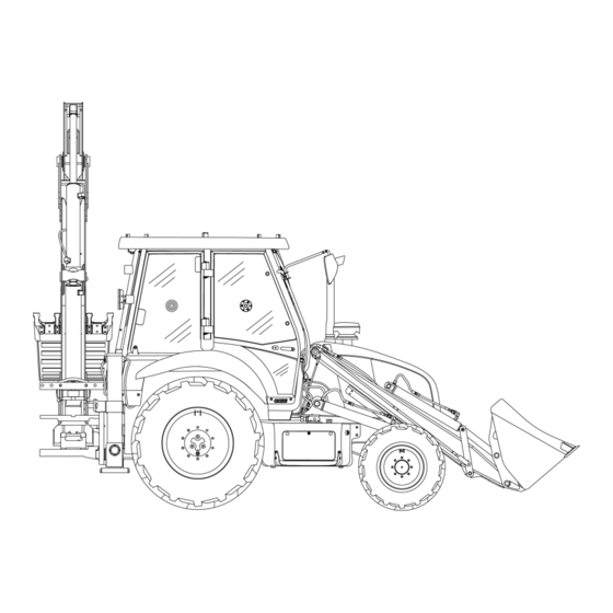
1 - GENERAL INFORMATION Component identification PTIL14TLB0011GB Loader bucket (with BDB if fitted) Boom Dipper arm Loader arm Front wheel hub 10. Backhoe bucket (with extendahoe if fitted) Fuel tank 11. Stabilizer 12. Hydraulic tank Rear wheel hub Windshield 13. Side shift frame Engine hood 1-10... -
Page 19: Safety Rules
2 - SAFETY INFORMATION 2 - SAFETY INFORMATION###_2_### Safety rules Throughout this manual and on machine safety signs, you will find the signal words DANGER, WARNING, and CAU- TION followed by special instructions. These precautions are intended for the personal safety of you and those working with you. - Page 20 2 - SAFETY INFORMATION Keep clear of moving parts. Loose clothing, jewelry, watches, long hair, and other loose or hanging items can become entangled in moving parts. Wear protective equipment when appropriate. DO NOT attempt to remove material from any part of the machine while it is being operated or while components are in motion.
- Page 21 Always have a qualified tire technician service the tires and wheels. If a tire has lost all pressure, take the tire and wheel to a tire shop or your CASE Dealer for service. Explosive separation of the tire can cause serious injury.
- Page 22 2 - SAFETY INFORMATION DO NOT weld to a wheel or rim until the tire is completely removed. Inflated tires can generate a gas mixture with the air that can be ignited by high temperatures from welding procedures performed on the wheel or rim. Removing the air or loosening the tire on the rim (breaking the bead) will NOT eliminate the hazard.
- Page 23 2 - SAFETY INFORMATION General battery safety Always wear eye protection when you work with batteries. Do not create sparks or have open flame near a battery. Ventilate the area when you charge a battery or use a battery in an enclosed area. Disconnect the negative (-) terminal first and reconnect the negative (-) terminal last.
- Page 24 Dispose of all fluids, filters, and containers in an environmentally safe manner according to local laws and regulations. Check with local environmental and recycling centers or your CASE Dealer for correct disposal information. Store fluids and filters in accordance with local laws and regulations. Use only appropriate containers for the storage of chemicals or petrochemical substances.
- Page 25 2 - SAFETY INFORMATION Mounting and dismounting Mount and dismount the machine only at designated locations that have handholds, steps, and/or or ladders. Do not jump off of the machine. Make sure that steps, ladders, and platforms remain clean and clear of debris and foreign substances. Injury may result from slippery surfaces.
-
Page 26: Ecology And The Environment
• Do not open the air-conditioning system yourself. It contains gases that should not be released into the atmosphere. Your CASE Dealer or air-conditioning specialist has a special extractor for this purpose and will have to recharge the system properly. -
Page 27: Hand Signals
2 - SAFETY INFORMATION Hand signals When operating the machine, never attempt to carry out tasks calling for fine control or to work in areas with poor visibility or during reverse travel, without seeking the assistance of a flagman. Make perfectly sure that you and the flagman understand the signals to be used. - Page 28 2 - SAFETY INFORMATION 4. Move away from me. PTIL12TLB0329AA 5. Go this far. PTIL12TLB0337AA 6. Stop all and hold. PTIL12TLB0344AA 7. Stop. PTIL12TLB0343AA 2-10...
- Page 29 2 - SAFETY INFORMATION 8. Emergency stop. PTIL12TLB0331AA 9. Raise load or bucket. PTIL12TLB0339AA 10. Lower load or bucket. PTIL12TLB0334AA 11. Raise load or bucket slowly. PTIL12TLB0340AA 2-11...
- Page 30 2 - SAFETY INFORMATION 12. Lower load or bucket slowly. PTIL12TLB0335AA 13. Turn machine left. PTIL12TLB0346AA 14. Turn machine right. PTIL12TLB0347AA 15. Roll back loader bucket. PTIL12TLB0341AA 2-12...
- Page 31 2 - SAFETY INFORMATION 16. Dump loader bucket. PTIL12TLB0330AA 17. Raise backhoe boom. PTIL12TLB0338AA 18. Lower backhoe boom. PTIL12TLB0333AA 19. Backhoe dipper in. PTIL12TLB0324AA 2-13...
-
Page 32: Backhoe Buckets
2 - SAFETY INFORMATION 20. Backhoe dipper out. PTIL12TLB0327AA 21. Backhoe bucket dig. PTIL12TLB0326AA 22. Backhoe bucket dump. PTIL12TLB0325AA 23. Retract telescopic dipper (If fitted). PTIL12TLB0322AA 2-14... - Page 33 2 - SAFETY INFORMATION 24. Extend telescopic dipper (If fitted). PTIL12TLB0332AA 2-15...
-
Page 34: Safety Signs
2 - SAFETY INFORMATION Safety signs External decals The following safety signs are placed on your machine as a guide for your safety and for those working with you. Walk around the machine and note the content and location of these safety signs before operating your machine. Keep safety signs clean and legible. - Page 35 2 - SAFETY INFORMATION 2. Crushing hazard PTIL13TLB1433AA 3. Crushing hazard PTIL13TLB1433AA 4. Crushing hazard PTIL13TLB1433AA 5. Objects falling hazard PTIL13TLB1434AA 2-17...
- Page 36 2 - SAFETY INFORMATION 6. Crushing hazard PTIL13TLB1433AA 7. Falling objects, keep distance PTIL13TLB1437AA 8. Falling hazard PTIL14TLB0053AA 2-18...
- Page 37 2 - SAFETY INFORMATION PTIL14TLB0013FB 1. Crushing hazard PTIL13TLB1433AA 2. Hyd oil level check PTIL14TLB0014AA 2-19...
- Page 38 2 - SAFETY INFORMATION 3. Tow hook point PTIL13TLB1445AA 4. Falling objects, keep distance PTIL13TLB1437AA 5. Crushing hazard PTIL13TLB1433AA 6. Crushing hazard PTIL13TLB1433AA 2-20...
- Page 39 2 - SAFETY INFORMATION 7. Crushing hazard PTIL13TLB1433AA Internal decals PTIL14TLB0061FB 1. Height warning PTIL14TLB0059AA 2-21...
- Page 40 2 - SAFETY INFORMATION 2. Brake fluid level warning PTIL13TLB1461AA 3. Maintenance information PTIL13TLB1460AA 4. Refer operator’s manual PTIL14TLB0060AA 5. Throttle lever position PTIL13TLB1441AA 2-22...
- Page 41 2 - SAFETY INFORMATION 6. Ignition key position PTIL12TLB0490AA 7. Loader operation PTIL13TLB1444AA PTIL12TLB0472FB 2-23...
- Page 42 2 - SAFETY INFORMATION 8. Boom control PTIL13TLB1443AA 9. Dipper control PTIL12TLB0488AA 10. Stabilizer control PTIL12TLB0489AA 2-24...
-
Page 43: Access To Operator's Platform
(2). Lift the handle (3) to open the doors from the inside. NOTICE: Use the left-hand door for entering or leaving the operator’s compartment. Use the right-hand door only in case of an emergency. WARNING Moving parts! Make sure all entry and mechanical access doors are properly closed before operating the machine. - Page 44 3 - CONTROLS AND INSTRUMENTS Windows Rear windows Turn the handle (1) on either side to unlock the window (2). Push the window outwards and upwards simultaneously to open it until it engages with the locking device. PTIL12TLB0189AB Side windows Unlock the top and bottom locks (1) and swing the win- dow outwards.
- Page 45 3 - CONTROLS AND INSTRUMENTS Side rear windows Turn the lock (1) downwards and swing the window out- wards using handle. The windows can be completely opened and locked to the front windows with the help of a locking mechanism. NOTICE: Make sure the window is completely locked.
-
Page 46: Operator's Seat
3 - CONTROLS AND INSTRUMENTS OPERATOR'S SEAT Operator's seat To operate the machine correctly with maximum efficiency and comfort, check that the operator’s seat and its adjust- ment controls are in good condition and then adjust the seat to suit the operator’s height. NOTE: Before using the controls, make sure that the seat is adjusted and positioned correctly. -
Page 47: Front Controls
3 - CONTROLS AND INSTRUMENTS FORWARD CONTROLS Front controls Starter switch key WARNING Misuse hazard! Before starting the engine, make sure you are fully aware of the location and the function of each control. Failure to comply could result in death or se- rious injury. - Page 48 Failure to observe this precaution may result in damage to the steering system components. NOTICE: In case of a broken steering hose, the machine cannot be steered, stop the machine immediately and contact your CASE Dealer.
-
Page 49: Pedal Controls
3 - CONTROLS AND INSTRUMENTS Pedal controls Engine accelerator This pedal (1) enables the engine speed to be increased or decreased. Press the pedal to increase the engine speed. Release the pedal to reduce the engine speed. This pedal is used for travel and for operating the loader attachment. - Page 50 3 - CONTROLS AND INSTRUMENTS Parking brake lever The parking brake is a mechanical link with lever type. WARNING Loss of control hazard! To prevent inadvertent machine movement, take care to avoid accidental contact with the gearshift levers. Always stop the engine, firmly apply the parking brake, and place all gearshift levers in neutral before leaving the machine.
-
Page 51: Transmission Controls
3 - CONTROLS AND INSTRUMENTS Transmission controls Power-Shuttle 1. Gearshift lever: It is possible to select four forward and four reverse travel gears. 2. Transmission disconnect button (on gearshift lever): Prior to changing gear press and hold down this switch which disengages transmission drive, select the re- quired gear with the gearshift lever and release the switch to reengage drive. - Page 52 3 - CONTROLS AND INSTRUMENTS Forward/reverse Power-Shuttle lever (travel direction change) To select the forward travel, engage the required gear ra- tio with the gearshift lever, with the engine idling, shift the Power-Shuttle lever from the neutral lock position (1) to the forward position (2).
- Page 53 3 - CONTROLS AND INSTRUMENTS NOTICE: To prevent possible damage to the transmission hydraulic clutches, never use the disconnect switch for inching the machine forward. Inching the machine for- ward with the button will cause the clutches to slip exces- sively and overheat.
-
Page 54: Right Hand Side Controls
3 - CONTROLS AND INSTRUMENTS RIGHT-HAND SIDE CONTROLS Right hand side controls Lever for direction indicators, main beam and front windshield wiper Located on the right of the steering wheel, this lever has four positions: Position “0”: Neutral Position “1”: The left-hand direction indicators and the di- rection indicator lamp under the steering wheel flash at the same speed. - Page 55 3 - CONTROLS AND INSTRUMENTS Bottom dump bucket control lever (optional) 1. Bottom dump bucket dumping control lever PTIL14TLB0222AB 3-13...
-
Page 56: Instrument Cluster - Front
3 - CONTROLS AND INSTRUMENTS INSTRUMENT CLUSTER Instrument cluster - Front PTIL12TLB0074FB 1. Direction indicator lamp: This lamp turns on when the direction indicators are working 2. Hazard light switch Press the button till it is locked. The direction indicators and the hazard light switch will flash simultaneously. Press the button again to turn it Off. -
Page 57: Instrument Cluster Panel – Side
3 - CONTROLS AND INSTRUMENTS Instrument cluster panel – Side PTIL14TLB0067FB Power point/mobile charger socket: Provides 12 V output Ignition key switch 4WD switch (if equipped): Switch it “ON” to engage the 4WD on your vehicle Fan switch Rear work light Rear windshield wiper switch Instrument cluster: The cluster incorporates warning and informatory visual signals HVAC control... -
Page 58: Instrument Cluster
DO NOT SWITCH OFF THE ENGINE. Let the engine idle till the light goes “OFF”. You can proceed once it is “OFF”. If it occurs frequently then contact your CASE Dealer. 11. High beam indicator (Blue color) Turns “ON”... - Page 59 12. High coolant temperature lamp (Red color) This turns “ON” when the engine coolant temperature is very high. Stop the vehicle immediately to prevent dam- age to the engine and contact your CASE Dealer for help. 13. The LCD display Displays the hours of usage of the machine hh:mm format.
-
Page 60: Heating, Ventilation, Air Conditioning (Hvac) Controls
3 - CONTROLS AND INSTRUMENTS Heating, Ventilation, Air Conditioning (HVAC) controls Cab with HVAC 1. Blower speed control knob: Turn the three-speed con- trol knob (1) to set the desired blower speed. 2. HVAC control knob: Turn the knob (2) to switch on the HVAC system. -
Page 61: Cab And Platform - Control Identification
3 - CONTROLS AND INSTRUMENTS CAB CONTROLS AND ADJUSTMENTS Cab and platform - control identification Operator’s compartment light This light is mounted on the roof. It can be turned “ON” by pressing the light and switched “OFF” by pressing the light again. - Page 62 3 - CONTROLS AND INSTRUMENTS Storage areas Located at the side instrument panels, these areas (1) can be used for cups, bottles etc. PTIL12TLB0081AB There is a provision made on the right hand side of the overhead panel in the cabin for storage. The storage (1) is provided with a netting to prevent stored objects from falling during machine operation.
-
Page 63: Loader Attachment Controls
3 - CONTROLS AND INSTRUMENTS LOADER ATTACHMENT CONTROLS Loader attachment controls WARNING Misuse hazard! Before starting the engine, make sure you are fully aware of the location and the function of each control. Failure to comply could result in death or se- rious injury. -
Page 64: Loader Attachment – Operation
3 - CONTROLS AND INSTRUMENTS Loader attachment – Operation Neutral and hold With the lever in the neutral/hold position “0”, the attach- ment movement can be stopped. As soon as the lever is released, it automatically returns to the neutral position “0” and the attachment remains in the position where it was when movement stopped. - Page 65 3 - CONTROLS AND INSTRUMENTS Loader bucket float control With the lever in position “3”, the bucket follows the con- tours of the ground without it being necessary to operate the lever. NOTE: In this position the lever does not automatically return to neutral when it is released.
- Page 66 3 - CONTROLS AND INSTRUMENTS Dumping with bottom dump bucket (if fitted) With the bottom dump bucket lever in reverse position “5”, the bucket opens (dumps). PTIL13TLB1751AB Automatic return to dig Lever must be moved to float (position 3) and roll back (position6) at the same time, diagonal operation.
- Page 67 3 - CONTROLS AND INSTRUMENTS Adjustment of self leveling linkage 1. Lower the loader to the ground. 2. Disconnect vertical linkage (3) at upper bell crank (1). 3. Raise loader arms so that the bottom hinge pin is 1520 mm (60 in) above the ground and fully roll back the bucket.
- Page 68 3 - CONTROLS AND INSTRUMENTS As a visual aid for the operator, while seated in the cab, the pointer mounted on the loader arm can be seen to align with the pointer on the self-leveling linkage, when the loader arms are lowered and the bucket is in the level digging position.
-
Page 69: Booms, Dippers, And Buckets - Control Identification
3 - CONTROLS AND INSTRUMENTS BACKHOE ATTACHMENT CONTROLS Booms, dippers, and buckets - Control identification NOTICE: Before using the backhoe attachment, make sure the stabilizers are completely lowered. Backhoe boom and backhoe attachment left-hand control lever The lever has five positions: Position “0”: Neutral/hold. - Page 70 3 - CONTROLS AND INSTRUMENTS PTIL14TLB0066HB 3-28...
- Page 71 3 - CONTROLS AND INSTRUMENTS Extendahoe operation (optional) PTIL14TLB0071FB Extendahoe control foot pedal (1). 3-29...
-
Page 72: Left-Hand Stabilizer Left-Hand Control Lever
3 - CONTROLS AND INSTRUMENTS STABILIZER MECHANICAL CONTROLS Left-hand stabilizer left-hand control lever The lever (1) has two positions: Position “A”: The left-hand stabilizer lowers. Position “B”: The left-hand stabilizer rises. PTIL12TLB0092AB 3-30... -
Page 73: Right-Hand Stabilizer Right-Hand Control Lever
3 - CONTROLS AND INSTRUMENTS Right-hand stabilizer right-hand control lever The lever (1) has two positions: Position “A”: The right-hand stabilizer lowers. Position “B”: The right-hand stabilizer rises. NOTE: To raise or lower the two stabilizers at the same time, operate the two levers simultaneously. NOTICE: Before machine travel or before using the loader attachment, make sure the stabilizers are com- pletely raised. -
Page 74: Slider Frame Control Pedal
3 - CONTROLS AND INSTRUMENTS Slider frame control pedal The pedal (1) has two positions: Position “ A”: The slider frame is free to slide. Position “ B”: The slider frame is locked in position. Press and hold the pedal in position A to unlock the slider frame. -
Page 75: Commissioning The Machine
Make sure that no objects or tools are left on the machine or in the operator’s compartment. Make sure you know how to evacuate the machine (emergency exit via the right-hand door) in case exit through the left-hand door is not possible. -
Page 76: Operating The Machine
4 - OPERATING INSTRUCTIONS Operating the machine WARNING Driving hazard! Check all controls and safety devices in a safe, open area before starting work. Failure to comply could result in death or serious injury. W0248A When using the machine, some precautions are necessary. Start the engine taking into account weather conditions. Regularly check the hour-meter to ensure servicing intervals are observed. -
Page 77: Road Operation
4 - OPERATING INSTRUCTIONS Road operation NOTICE: Road speed is subject to restrictions. It is the operator’s responsibility to limit his speed accordingly. Before carrying out any road travel, lock the attachments and install the safety systems required by regulations. The machine must be within the maximum dimensions permitted on the road in accordance with local road traffic regulations. -
Page 78: Job Site Operation
4 - OPERATING INSTRUCTIONS Job site operation On job sites on the public highway, use regulation signals, taking into account the working range of the machine. Local regulations define the number, type and location of reflective strips. Be vigilant, be aware of places where other persons are working close to your working area. -
Page 79: Starting The Engine
4 - OPERATING INSTRUCTIONS STARTING THE UNIT Starting the engine 1. Check that the seat (1) is properly locked in the loader attachment working position. 2. Adjust the seat and fasten the seat belt. 3. Check that the parking brake lever (2) is in raised po- sition. -
Page 80: Assisted Starting (Jump-Starting)
• If warning lamps do not turn On, the battery is faulty (completely discharged or with short-circuit inside). In this case the machine must not be started, as the alternator would then be damaged. Install a functional battery before jump-starting. -
Page 81: Starting The Engine - At Low Temperatures
4 - OPERATING INSTRUCTIONS Starting the engine - At low temperatures When starting a cold engine at temperatures below 5 °C (41 °F), open the throttle fully. Turn the key to “ON” until the engine starts, then release the key. If the engine fails to start, wait for one minute and repeat the starting proce- dure. -
Page 82: Stopping The Engine
4 - OPERATING INSTRUCTIONS STOPPING THE UNIT Stopping the engine Ensure the direction-of-travel control lever (1) is in the neutral position. Place the gearshift lever (2) in neutral position. Engage the parking brake (3). Allow the engine to run at idle speed for about 1 min in order for the tur- bocharger to be lubricated correctly. -
Page 83: Moving The Unit
4 - OPERATING INSTRUCTIONS MOVING THE UNIT Moving the unit NOTE: After road travel, remove all road safety devices before carrying out any job site travel. 1. Make sure that the engine accelerator lever (2) is in low idle position. 2. - Page 84 4 - OPERATING INSTRUCTIONS 8. Press the transmission disconnect button (5) and place the gearshift lever (6) in first gear. 9. Press the brake pedals down and release the parking brake. PTIL12TLB0106AB 10. Place the direction of travel control lever (4) in the desired position.
- Page 85 4 - OPERATING INSTRUCTIONS 2WD or 4WD NOTE: The engagement or disengagement of the 4WD must be carried out with a stopped machine. NOTE: Machines with or without four wheel drive should not be allowed to exceed 40 km/h (24.9 mph). A freewheel descent or towing the machine at excessive speed may cause loss of control, personal injury to the operator or damage the transmission.
-
Page 86: Parking The Unit
4 - OPERATING INSTRUCTIONS PARKING THE UNIT Parking the unit When parking the machine, some precautions are neces- sary. Move the machine to a level and firm ground, away from any soft ground, excavations or poorly shored cavity. Lower the loader attachment to the ground. Place the backhoe attachment in the road travel po- sition. -
Page 87: Requirements For Road Travel
5 - TRANSPORT OPERATIONS 5 - TRANSPORT OPERATIONS###_5_### ROAD TRANSPORT Requirements for road travel Install the safety systems in compliance with legal requirements. Make sure your machine complies with the local legislation. 1. Backhoe attachment locking pin, install the pin in the locking bar. -
Page 88: Precautions For Road Travel
5 - TRANSPORT OPERATIONS Precautions for road travel WARNING Avoid injury! Before starting the engine, securely fasten the seat belt. The seat belt can help ensure your safety if it is properly used and maintained. Never wear a seat belt loosely or with slack in the belt system. Never wear the belt if it is twisted or pinched between the seat structures. -
Page 89: Preparing The Machine For Road Travel
5 - TRANSPORT OPERATIONS PREPARING FOR ROAD TRANSPORT Preparing the machine for road travel 1. Make sure that the engine accelerator lever (2) is in low idle position. PTIL12TLB0430AB 2. Place the seat in the backhoe attachment position. 3. Place the backhoe attachment in road travel position. PTIL14TLB0021AA 4. - Page 90 5 - TRANSPORT OPERATIONS 7. Clean the license plates if necessary. 8. Make sure the doors are properly closed and that the engine guard is locked. 9. Make sure that the two brake pedals are locked to- gether by means of the relevant pin (7). PTIL12TLB0114AB 10.
- Page 91 5 - TRANSPORT OPERATIONS 14. Press the transmission disconnect button (12) and then push the gearshift lever (13) in first gear. 15. Release the button (12). PTIL12TLB0118AB 16. Press the brake pedals and release the parking brake. 17. Position the direction-of-travel control lever (9) for- wards.
-
Page 92: Setting The Backhoe Attachment In Road Travel Position
5 - TRANSPORT OPERATIONS Setting the backhoe attachment in road travel position NOTE: The instruments represented may not exactly correspond to the instruments on your machine. NOTICE: This procedure must be used for road travel, for operating the loader attachment, when transporting the machine on a trailer and when parking the machine. - Page 93 5 - TRANSPORT OPERATIONS 10. Lock the backhoe attachment. 11. Raise the stabilizers completely. 12. Run the engine at low idle speed. 13. Turn the seat round to the loader attachment position. 14. Raise the loader bucket. 15. Stop the engine and remove the starter switch key. PTIL12TLB0125AB...
-
Page 94: Locking Or Unlocking The Backhoe Attachment
5 - TRANSPORT OPERATIONS Locking or unlocking the backhoe attachment Before undertaking any road travel, the backhoe attachment must be “locked” in transport position. In order to do this, retract the dipper completely against the boom and then fully raise the boom so that the lock bar engages on the boom pins. -
Page 95: Machine Transport (On A Trailer)
5 - TRANSPORT OPERATIONS SHIPPING TRANSPORT Machine transport (on a trailer) WARNING Transport hazard! The machine can slip or fall from a ramp or trailer. Make sure the ramp and trailer are not slippery. Remove all oil, grease, ice, etc. Move the machine on or off the trailer with machine centered on the trailer or ramp. -
Page 96: Towing The Machine
W0259A The machine should only be towed in case of failure. Before towing make sure that it can be towed without causing further damage. Whenever possible carry out the repair at the site or consult your CASE Dealer. If the machine is on the public road, make sure that no component of the machine projects onto the road. - Page 97 5 - TRANSPORT OPERATIONS 4. If the engine is running, make sure the 4WD (is appli- cable) is disengaged. NOTICE: If the engine is not running, the force necessary to turn the steering wheel will be higher. To tow the ma- chine, attach a towing bar to one of the hooking points shown by the decals.
- Page 98 5 - TRANSPORT OPERATIONS 5-12...
-
Page 99: Operating The Machine In Cold Weather
6 - WORKING OPERATIONS 6 - WORKING OPERATIONS###_6_### GENERAL INFORMATION Operating the machine in cold weather NOTICE: Before operating at temperatures below -1 °C (30.2 °F), operate the engine for approximately 15 min at a speed below 1000 RPM to warm the oil up to the normal operating temperature. Fuel Refill the fuel tank after each working day to prevent the formation of condensation and the entry of water into the fuel system. -
Page 100: Operating The Machine In High Altitude
3000 m (9843 ft) and tempera- tures up to 50 °C (122 °F) for mobile operations. If the en- gine will be operated under severe conditions (at higher altitudes or temperatures) contact the CASE Dealer for further guidelines. Observe the following recommendations: 1. -
Page 101: Operating The Machine In High Temperatures
Observe the following recommendations: 1. Keep the coolant at the correct level in the coolant reservoir and in the radiator. 2. Visit your CASE Dealer and have the de-aeration cap tested before hot weather starts. Replace the cap as required. -
Page 102: Operating The Machine In Water
6 - WORKING OPERATIONS Operating the machine in water Make sure that the bed of the stream or stretch of water can support the weight of the machine. The level of the water must not exceed the height of the centre of the front wheels. -
Page 103: Lifting The Machine
6 - WORKING OPERATIONS Lifting the machine NOTICE: Before lifting the machine, it is essential to place the backhoe attachment in the road travel position. The hooking points for the machine are shown by decals. NOTICE: Never use any other hooking points than those shown by the decals. -
Page 104: Organizing The Job Site
6 - WORKING OPERATIONS LOADER ATTACHMENT Organizing the job site Always use the shortest possible work cycles. The loca- tion provided for the trucks is an all important element. Spend a little time leveling the work area. A smooth work- ing surface facilitates the work of the machine and moving and parking the trucks. -
Page 105: Transmission Disconnect Button
6 - WORKING OPERATIONS Transmission disconnect button To give maximum power to the hydraulic system, press the disconnect button (1) and hold it down. This will cause the transmission to revert to neutral. Release the discon- nect button to engage the transmission again. NOTICE: When the button is pressed, the wheels of the machine are free. -
Page 106: Operating The Loader Attachment
6 - WORKING OPERATIONS Operating the loader attachment WARNING Unexpected movement! Implements equipped with rear-mounted attachments or rear-towed equipment may tip back when dis- connecting from the tractor in the transport position. Use a rear jack stand to prevent the implement from tipping back. - Page 107 6 - WORKING OPERATIONS WARNING Falling objects! Dirt slides can be dangerous. Exercise ex- treme care when undercutting high banks. Watch for falling rocks and cave-ins. Failure to comply could result in death or se- rious injury. W0021A Dump the bucket completely, raise the attachment and then release the transmission disconnect button.
- Page 108 6 - WORKING OPERATIONS To backfill a trench efficiently it is necessary to move the maximum amount of soil without losing speed. If “stall” oc- curs downshift or reduce the depth of cut. If the machine is not working at capacity in the gear selected, increase the depth of cut.
-
Page 109: Loader Attachment Safety Strut
6 - WORKING OPERATIONS Loader attachment safety strut Located on the left-hand side of the loader attachment, this safety strut enables the loader attachment to be locked in the raised position for maintenance or servicing the unit. Locked position 1. Completely raise the loader attachment. 2. -
Page 110: Loader Bucket – Removal
6 - WORKING OPERATIONS Loader bucket – Removal Move the machine to a level and firm ground. Lower the bucket to the ground in dump position (tilted completely forward). Stop the engine and remove the starter switch key. If the machine is fitted with a 4x1 bucket, release the pressure from the bucket circuit. -
Page 111: Loader Bucket – Install
6 - WORKING OPERATIONS Loader bucket – Install Make sure all bushings are completely clean. Remove any dirt or foreign matter, if necessary. Start the engine. Use the attachment controls to engage the attach- ment between the bucket lugs. Reinstall the arm/bucket pins (1) and then install the relevant retaining pins and rings. -
Page 112: Backhoe Attachment
NOTICE: The backhoe attachment should be operated between 1425 - 1475 RPM as measured by a tachometer. Please contact CASE Dealer for assistance. If you try to use the backhoe bucket for digging too wide a trench, you may cause a stall situation (where the dipper control lever is tilted towards the rear but nothing happens). -
Page 113: Setting The Backhoe Attachment In Working Position
6 - WORKING OPERATIONS Setting the backhoe attachment in working position WARNING Overturning hazard! Be careful when you operate the machine on a hillside. You must be in the operator's seat (loader operation position) when you move the machine forward. Always engage the parking brake and shift the direction control lever and the transmission to neutral before you operate the backhoe. -
Page 114: Operating The Backhoe Attachment
6 - WORKING OPERATIONS Operating the backhoe attachment Digging method PTIL12TLB0154EA PTIL12TLB0383EB Wrong Wrong Correct The backhoe attachment will dig in The bucket is pushed upwards. This will increase the cycle time and cause a stall NOTICE: Never operate any of the backhoe attachment control levers with arm locked in transport position. NOTICE: The safe working load of the backhoe attachment is calculated using a standard bucket, therefore, when using another bucket or attachment for lifting or handling a load, the weight of the bucket or attachment must be taken into account when calculating the rated load of the backhoe attachment. -
Page 115: Filling The Backhoe Bucket
6 - WORKING OPERATIONS Filling the backhoe bucket Fill the backhoe bucket by maneuvering the dipper. Keep the bottom of the backhoe bucket parallel to the cut. The backhoe bucket teeth and blade must cut the ground like the blade of a knife. The depth of dig varies depend- ing on the type of material. -
Page 116: Moving The Machine Forwards When Working
6 - WORKING OPERATIONS Moving the machine forwards when working It is possible to use the backhoe attachment to move the machine forward at the same time as the excava- tion. Make sure that the front wheels are straight. Set the engine speed to 1000 RPM. Release the parking brake. -
Page 117: Trenching
6 - WORKING OPERATIONS Trenching Trenching is the basic backhoe excavating operation. Other digging operations are merely variations of this basic function (filling the bucket, dumping the bucket and moving the machine forward). While trenching, it is generally important to maintain a level trench bottom. This is accomplished by setting the bucket at the correct angle of approach. - Page 118 6 - WORKING OPERATIONS To finish the rear wall crowd in the bucket, while lifting with the boom, keeping the edges of the bucket horizontal. The platform will also reduce the possibility of the machine creeping rearwards if hard digging is encountered. NOTICE: Do not backfill a trench using the swing device to swing the bucket sideways.
-
Page 119: Backhoe Bucket Remove
6 - WORKING OPERATIONS Backhoe bucket Remove 1. Move the machine to a level and firm ground. 2. Lower the stabilizers and place the bucket on the ground. 3. Stop the engine and remove the starter switch key. 4. Remove the lock rings and pins and the rod/bucket link pin (1). -
Page 120: Backhoe Bucket Install
6 - WORKING OPERATIONS Backhoe bucket Install 1. Start the engine. 2. Extend the bucket cylinder rod to bring the connecting rod to their housing. 3. Reinstall the arm/bucket link pin (1) and install the lock rings and pins. 4. Slightly raise the attachment and operate the bucket and dipper control to align the dipper hole with the bucket lugs. -
Page 121: Backhoe Bucket – Digging Angle
6 - WORKING OPERATIONS Backhoe bucket – Digging angle It is possible to change the backhoe bucket opening an- gle, depending on the work which is to be carried out. Position (1): Bucket maximum power. Position (2): Enables the bucket to open by 10°more and, therefore, to dig vertical side trenches closer to the ma- chine. - Page 122 6 - WORKING OPERATIONS 6-24...
-
Page 123: Fluids And Lubricants
7 - MAINTENANCE MAINTENANCE###_7_### GENERAL INFORMATION Fluids and lubricants S.N. Usage Specification Brand 570T 16.00 l (4.23 US gal) Transmission oil 2WD SAE 15W30 CASE TRANSPOWER 18.50 l (4.89 US gal) Transmission oil 4WD SAE 15W30 CASE TRANSPOWER Rear axle oil... -
Page 124: Fuel
7 - MAINTENANCE Fuel The use of improper or adulterated fuel can result in a loss of power of the engine, damage to fuel system and engine and may cause high fuel consumption. If the temperature falls below the fuel cloud point (point at which wax begins to form) the wax crystals will cause power loss or will prevent the engine from starting. -
Page 125: Fuel Storage
7 - MAINTENANCE Fuel storage Prolonged storage of fuel can lead to the accumulation of impurities and condensation in the fuel. Engine trouble can often be traced to the presence of water in the fuel. The storage tank must be placed outside and the temperature of the fuel should be kept as low as possible. -
Page 126: Fuel Tank
7 - MAINTENANCE Fuel tank The fuel tank (1) is located on the left-hand side of the machine, under the cab. NOTE: Tank capacity 142 l (38 US gal). It is possible to fill fuel through the plug (2). In cold weather, use a fuel suitable to the ambient temperature and refill at the end of each working day, in order to prevent condensation. -
Page 127: Hydraulic Oil
7 - MAINTENANCE Hydraulic oil Hydraulic oil is not water- soluble, this can cause the formation of condensation water in the hydraulic oil tank, es- pecially after the machine has been left unused for a long time. If water contamination is noticed then replace the hydraulic oil. -
Page 128: Hydraulic Oil Tank
7 - MAINTENANCE Hydraulic oil tank The hydraulic oil tank (1) is located on the right-hand side of the machine, under the cab. NOTE: Tank capacity 65 l (17 US gal). The oil level can be checked through the sight glass (3). Remove the breather with oil filing cap (2), by means of the special wrench supplied with the machine to topup the oil. -
Page 129: Engine Oil Viscosity
7 - MAINTENANCE Engine oil viscosity As a general rule, multi-grade oils must be used. In closed rooms heated to temperatures > 5 °C (41 °F), it is also possible to use single-grade oils. As the viscosity of lubri- cating oils varies according to the temperature, the tem- perature of the place where the engine will be used is de- cisive for choosing the oil viscosity grade ( SAE grade). -
Page 130: Safety Instructions
NOTE: There is a risk of serious injury if maintenance or repairs are not performed correctly. If you do not under- stand the maintenance procedures, consult your CASE Dealer. Make sure you know the position and function of every control. -
Page 131: Machine Safety
7 - MAINTENANCE Machine safety Before performing any maintenance or repair operation, make sure the conditions are safe to perform any task on the machine. 1. Move the machine to a level and firm ground, away from soft ground, excavations or poorly shored cavity. 2. -
Page 132: Work Hours And Intervals
7 - MAINTENANCE Work hours and intervals Work hours and intervals One of the premises for the manufacturer to satisfy the warranty obligations is the regular performance of all inspec- tion, maintenance and repair operations prescribed, according to the instructions given in this manual, as well as the use of original spare parts. -
Page 133: Maintenance Chart
6. The machine must stop smoothly in a straight line and the brake pedal effort must feel firm. NOTICE: If the machine does not stop in a straight line or if the brake pedal effort feels soft, contact your CASE Dealer for service. 7-11... -
Page 134: Parking Brake
7 - MAINTENANCE Parking brake The parking brake is not serviceable. If a reduction of the braking action is detected, contact your CASE Dealer. 7-12... -
Page 135: Fuses And Lamps
7 - MAINTENANCE Fuses and lamps Fuse details The machine is equipped with a fuse located on the side console. Side console box 1. Turn the thumb screws (1) to loosen the panel cover (2) for the fuse box. Remove the panel cover. 2. - Page 136 7 - MAINTENANCE Lamp details Before using the machine, it is recommended to check that all lights are clean and correctly operating. Lamp wattage Sl No. Lamp description Head lamp 65 W/ 55 W Front work light 55 W Rear work light 55 W Stop lamp 21 W...
-
Page 137: Functionality Of Controls And Lamps
7 - MAINTENANCE Functionality of controls and lamps Before using the machine, it is recommended to check that all controls, instruments and lamps in the operator’s com- partment are correctly operating. 7-15... -
Page 138: Drive Belts - Check
7 - MAINTENANCE Drive belts - Check 1. Move the machine to a level and firm ground. PTIL14TLB0009AA 2. Visually check the condition of the belt (1). 3. Replace if it is worn or damaged as described in the section “As required”. PTIL12TLB0178AB 7-16... -
Page 139: Engine Oil Level - Check
7 - MAINTENANCE Engine oil level - Check Engine oil level check 1. Move the machine to a level and firm ground. 2. Raise the loader attachment and install the safety sup- port strut. 3. Place the backhoe attachment in the road travel posi- tion. -
Page 140: Transmission Oil Level - Check
7 - MAINTENANCE Transmission oil level - Check 1. Move the machine to a level and firm ground. 2. Raise the loader attachment and install the safety sup- port strut. 3. Ensure the direction-of-travel lever and gearshift lever are in neutral position. 4. -
Page 141: Engine Coolant Level - Check
7 - MAINTENANCE Engine coolant level - Check 1. Move the machine to a level and firm ground. 2. Lower the loader attachment to the ground. 3. Place the backhoe attachment in the road travel posi- tion. 4. Place the direction-of-travel lever and gearshift lever in neutral position. -
Page 142: Hydraulic Oil Level - Check
7 - MAINTENANCE Hydraulic oil level - Check 1. Follow machine safety position. (Refer Engine - Safety rules) 2. Release any possible residual pressure from the hy- draulic system by moving the control levers in all direc- tions. 3. Check the hydraulic oil level in the tank (1) by means of the level gauge (2) after waiting for the oil to reach the ambient temperature. -
Page 143: Fuel Tank Level - Check – Level
7 - MAINTENANCE Fuel tank level - Check – Level WARNING Fire hazard! When handling diesel fuel, observe the follow- ing precautions: 1. Do not smoke. 2. Never fill the tank when the engine is run- ning. 3. Wipe up spilled fuel immediately. Failure to comply could result in death or seri- ous injury. -
Page 144: Restriction Indicator– Check
7 - MAINTENANCE Restriction Indicator– Check 1. Move the machine to a level and firm ground. 2. Raise the loader attachment and install the safety sup- port strut. 3. Place the backhoe attachment in the road travel posi- tion. 4. Ensure the direction-of-travel lever and gearshift lever are in neutral position. -
Page 145: Grease Points – Lubricate
7 - MAINTENANCE Grease points – Lubricate Drive shaft’s coupling Grease fittings (1). PTIL12TLB0219AB Front axle swivel bearing Grease fittings (1). NOTE: The number of grease points may vary depending on the type of accessory installed. PTIL12TLB0212AB 7-23... - Page 146 7 - MAINTENANCE Loader and backhoe attachment PTIL14TLB0040FB 1. Loader attachment 2. Backhoe attachment 7-24...
-
Page 147: Engine Oil And Oil Filter – Change
7 - MAINTENANCE FIRST 50 HOURS Engine oil and oil filter – Change 1. Follow Machine safety position (Refer Engine - Safety rules) 2. Open and raise the engine tilt hood. 3. Place a container with suitable capacity under the en- gine. - Page 148 7 - MAINTENANCE 13. Fill 11 l (3 US gal) engine oil. 14. Start the engine and let it run for several minutes and then check the level again by means of the dipstick. 15. If necessary, top up to compensate the quantity of oil used for filling the cartridge.
-
Page 149: Fan / Alternator Belt Tension
7 - MAINTENANCE Fan / alternator belt tension 1. Move the machine to a level and firm ground. 2. Raise the loader arm and put the safety strut. 3. Place the backhoe attachment in the road travel posi- tion. 4. Ensure the direction-of-travel lever and gearshift lever are in neutral position. -
Page 150: Battery Electrolyte Level - Check
7 - MAINTENANCE Battery electrolyte level - Check Open the battery compartment cover. Remove the vent plugs and check the level in each battery cell. Ensure to maintain the electrolyte level up to the MAX mark. Top up if necessary. 7-28... -
Page 151: Wheels Re-Torque
7 - MAINTENANCE EVERY 100 HOURS Wheels re-torque 1. Move the machine to a level and firm ground. 2. Lower the loader attachment to the ground. 3. Place the backhoe attachment in the road travel posi- tion. 4. Place the direction-of-travel lever and gearshift lever in neutral position. -
Page 152: Hydraulic System Breather - Clean
7 - MAINTENANCE Hydraulic system breather - Clean 1. Follow Machine safety position. (Refer Engine - Safety rules). 2. Clean the area around the cap. 3. Remove the cap (1) using the wrench (2) supplied with the machine. 4. Make sure that no dirt enter the hydraulic oil tank. 5. -
Page 153: Battery Check
7 - MAINTENANCE Battery check 1. Follow Machine safety position. (Refer Engine - Safety rules) 2. Open the battery compartment cover. 3. Disconnect the negative terminal. 4. Disconnect the positive terminal. 5. Remove the vent plugs and check the level in each battery cell. -
Page 154: Front Axle Breather (4Wd Only) - Clean
7 - MAINTENANCE Front axle breather (4WD Only) - Clean 1. Follow Machine safety position. (Refer Engine - Safety rules) 2. Clean the area around the breather valve (1). 3. Loosen and remove the valve. 4. Clean the breather valve (1) with a detergent solution. NOTE: Follow the instructions for the detergent solution. -
Page 155: Water Separator Drain
7 - MAINTENANCE Water separator drain 1. Follow Machine safety position. (Refer Engine - Safety rules) 2. Place a container underneath the water draining plug. 3. Unscrew the plug (1) and drain the water. 4. Tighten the plug. PTIL12TLB0194AB 7-33... -
Page 156: Rear Axle Differential Oil - Check
7 - MAINTENANCE Rear axle differential oil - Check 1. Follow Machine safety position. (Refer Engine - Safety rules). 2. Unscrew and remove the plug (1). 3. Check the level by checking if the oil reaches the height of the plug hole. 4. -
Page 157: Engine And Cabin Mounting Bolts Re-Torque
7 - MAINTENANCE Engine and cabin mounting bolts re-torque 1. Follow Machine safety position. (Refer Engine - Safety rules) 2. Retorque the engine mounting bolts to torque of 90.00 - 100.00 N·m (66.38 - 73.76 lb ft). PTIL13TLB0730AA 3. Retorque the cabin mounting bolts (1) to a torque of 301 N·m (222.01 lb ft). -
Page 158: Front Axle Hub Oil Level (4Wd Only) – Check
7 - MAINTENANCE Front axle hub oil level (4WD only) – Check 1. Follow Machine safety position. (Refer Engine - Safety rules) 2. Unscrew and remove the plug (1). 3. Check the level by checking if the oil reaches the height of the plug hole. -
Page 159: Stabilizer Wear Pads Adjust
7 - MAINTENANCE EVERY 250 HOURS Stabilizer wear pads adjust Your machine is fitted with stabilizer sleeve locking with plastic pad arrangement to provide comfort to the operator during backhoe operation by reducing the play between sleeve & vertical outer. When machine is in operation there is a defined clearance between vertical outer &... - Page 160 7 - MAINTENANCE 3. Insert & count the number of shims (4) in step cre- ated between sleeve locking (3) & welded boss (6) in pressed condition as shown in figure. 4. Add one more shim (4) to the number of shims (4) count in Step 3 to front of cover sleeve locking (3).
-
Page 161: Engine Oil And Oil Filter – Change
7 - MAINTENANCE EVERY 500 HOURS Engine oil and oil filter – Change 1. Follow Machine safety position (Refer Engine - Safety rules) 2. Open and raise the engine tilt hood. 3. Place a container with suitable capacity under the en- gine. - Page 162 7 - MAINTENANCE 13. Fill 11 l (3 US gal) engine oil. 14. Start the engine and let it run for several minutes and then check the level again by means of the dipstick. 15. If necessary, top up to compensate the quantity of oil used for filling the cartridge.
-
Page 163: Mud Filter - Change
7 - MAINTENANCE Mud filter - Change 1. Follow Machine safety position. (Refer Engine - Safety rules) 2. Open and raise the engine tilt hood 3. Place a container with suitable capacity under the filter. 4. Hold the primer (2) and loosen the breather screw (1). PTIL12TLB0235AB 5. -
Page 164: Fuel Filter - Change
7 - MAINTENANCE Fuel filter - Change 1. Follow machine safety position. (Refer Engine - Safety rules) 2. Open and raise the engine tilt hood. 3. Clean the filter assembly externally. 4. Loosen the bleed screw (2). 5. Unscrew the fuel filters (1) and discard. 6. -
Page 165: Powershuttle Transmission – Oil Change
7 - MAINTENANCE EVERY 1000 HOURS Powershuttle transmission – oil change 1. Follow Machine safety position. (Refer Engine - Safety rules) 2. Open and raise the engine tilt hood. 3. Remove the dipstick (1). NOTE: Change the oil while the transmission is still warm, the oil will flow easily. -
Page 166: Transmission Oil Filter - Replace
7 - MAINTENANCE Transmission oil filter - Replace 1. Follow machine safety position. (Refer Engine - Safety rules) 2. Open and raise the engine tilt hood. 3. Clean the area around the filter head. PTIL14TLB0009AA 4. Place a container with suitable capacity under the filter (1). -
Page 167: Transmission Suction Strainer - Cleaning
7 - MAINTENANCE Transmission suction strainer - Cleaning 1. Follow Machine safety position. (Refer Engine - Safety rules) 2. Remove the cap screws (2) from transmission assem- bly (1). 3. Remove the screen cover (3). PTIL13TLB0202AB 4. Remove the strainer (4) and O-ring (5). 5. -
Page 168: Hydraulic Oil Filter - Replace
7 - MAINTENANCE Hydraulic oil filter - Replace 1. Follow Machine safety position. (Refer Engine - Safety rules) 2. Clean top portion of the tank. 3. Remove breather (1) with a special tool to release pres- sure inside tank. PTIL12TLB0457AB 4. -
Page 169: Front Axle Hub Oil (4Wd Only) - Replace
7 - MAINTENANCE Front axle hub oil (4WD Only) - Replace 1. Follow Machine safety position. (Refer Engine - Safety rules) 2. Slightly raise the front part of the machine by means of the loader attachment, until the front wheels are no longer in contact with the ground. -
Page 170: Rear Axle Hub Oil - Replace
7 - MAINTENANCE Rear axle hub oil - Replace 1. Follow Machine safety position. (Refer Engine - Safety rules) 2. Lower the stabilizer and raise the machine until the rear wheels are no longer in contact with the ground. 3. Manually position the wheel until the hole of the plug (1) is at the bottom. -
Page 171: Front Axle Differential Oil (4Wd Only) - Replace
7 - MAINTENANCE Front axle differential oil (4WD Only) - Replace 1. Follow Machine safety position. (Refer Engine - Safety rules) 2. Place a container with suitable capacity under the plug (1). 3. Unscrew and remove the plugs (1) and (2). 4. -
Page 172: Rear Axle Differential Oil - Replace
7 - MAINTENANCE Rear axle differential oil - Replace 1. Follow Machine safety position. (Refer Engine - Safety rules) 2. Place a container with suitable capacity under the plug (1). 3. Unscrew and remove the plugs (1) and (2). 4. Let the oil drain completely (1). 5. -
Page 173: Front Axle - Hub Greasing 2Wd
7 - MAINTENANCE Front axle - Hub greasing 2WD 1. Follow Machine safety position. (Refer Engine - Safety rules) 2. Support the vehicle and remove front wheel. PTIL13TLB0732AA 3. Open the plug (1) and the cover (2). PTIL12TLB0557AB 4. Fill grease in the hole (1) until the excess grease purges from the bearing rollers. - Page 174 7 - MAINTENANCE 6. Install front wheel. 7. Tighten the wheel nuts (1) to a torque of 196.13 N·m (144.66 lb ft). PTIL12TLB0190AB 7-52...
-
Page 175: Check The Fuel Injector
Check the fuel injector NOTE: Injector check procedure needs to be done only by an authorised personnel. Kindly contact your nearest CASE Dealer for further details. Failure to comply may lead to machine failure. EVERY 2000 HOURS Brake oil - Replace 1. -
Page 176: Hydraulic Oil - Replace
7 - MAINTENANCE Hydraulic oil - Replace NOTE: When draining, the hydraulic oil must be at operating temperature. Raise the loader and backhoe completely. Switch Off the engine and allow the oil to drain to hydraulic tank and then drain the oil. 1. -
Page 177: Engine Coolant - Replace
7 - MAINTENANCE Engine coolant - Replace 1. Follow Machine safety position. (Refer Engine - Safety rules) 2. Place a container with sufficient capacity under the ra- diator drain cock. PTIL14TLB0042AA 3. Unscrew and remove the cap (2) from the radiator (1). CAUTION Burn hazard! Hot coolant can spray out if you remove the... - Page 178 12. Fill the coolant reservoir (1) with coolant solution. NOTE: Always use genuine and approved lubricants. Con- sult your CASE Dealer for any further information. NOTE: Always fill the cooling system with coolant slowly to prevent the formation of air bubbles.
-
Page 179: Radiator And Oil Cooler Fin - Cleaning
7 - MAINTENANCE Radiator and oil cooler fin - Cleaning 1. Follow Machine safety position. (Refer Engine - Safety rules) 2. Raise the loader and put safety strut. 3. Remove the front grille. 4. Unscrew the fixing screw and remove the intercooler. 5. -
Page 180: Engine Air Filter
7 - MAINTENANCE AS REQUIRED Engine air filter Servicing instructions A. Clean primary element: When service indicator shows red band. B. Replace primary element: When servicing indica- tor shows red band even after cleaning or after two cleaning intervals if holes or tears are found in el- ement. - Page 181 7 - MAINTENANCE 5. Extract the safety filter element (4). NOTICE: The safety filter element must not be cleaned. It must be replaced once per year, or when main element is replaced. 6. Clean the inside of the filter body by means of a clean cloth.
-
Page 182: Tires Pressure - Check
• Internal damage. • Irregular wear and shortened life. An excessive pressure “C” determines a higher sensitive- ness to damage in case of shocks and in extreme condi- tions, the rim could get deformed or the tire may burst. Inflating procedure 1. - Page 183 7 - MAINTENANCE Inflating pressure details Type of rear tire Front tires Rear tires 1.79 bar (26 psi) Standard Rear 5.52 bar (80 psi) Heavyduty rear 2.76 bar (40 psi) Type of rear tire Front tires Rear tires Standard Rear 1.79 bar (26 psi) 2.41 bar (35 psi) Heavyduty rear...
-
Page 184: Radiator - Cleaning
7 - MAINTENANCE Radiator - Cleaning 1. Follow Machine safety position. (Refer Engine - Safety rules). 2. Raise the loader and put safety strut. 3. Remove the front grille. ATTENTION: Before using compressed air, take the nec- essary precautions to protect your face. 4. -
Page 185: Condenser - Cleaning
7 - MAINTENANCE Condenser - Cleaning 1. Follow Machine safety position. (Refer Engine - Safety rules). 2. Raise the loader and put safety strut. 3. Remove the front grille. 4. Clean the condenser (1) with water jet to remove dust and mud. -
Page 186: Pollen Filter - Cleaning
7 - MAINTENANCE Pollen filter - Cleaning 1. Follow Machine safety position. (Refer Engine - Safety rules). 2. Before servicing the pollen filter located under the oper- ator’s seat, switch off the blower and close all windows and one door. ATTENTION: In humid conditions, do not switch on the blower prior to servicing the pollen filter. -
Page 187: Storing The Machine
This procedure is a good starting point but may not be all inclusive. If you have questions about storing your machine, contact your CASE Dealer. 1. Prior to storing, inspect the machine for visible signs of wear, breakage or damage. -
Page 188: Short Term Storage
7 - MAINTENANCE Short term storage If the machine is to remain unused for a period exceeding 30 days, store it under cover or cover it with a waterproof tarpaulin. Clean the machine completely. Paint all surfaces of the machine where the paint work is damaged, to avoid rust. -
Page 189: Storing The Engine
7 - MAINTENANCE Storing the engine If the engine is to be left unused for a long time, it is nec- essary to conserve it against rust formation. 1. Clean the engine with a high-pressure device. 2. Take the engine to the operating pressure, then stop it. 3. -
Page 190: Battery Storage
7 - MAINTENANCE Battery storage Remove the batteries from the machine. Store them on a wooden table in a dry, cool, well ventilated room, if possible at a temperature above 0 °C (32 °F) [optimum temperature 20 °C (68 °F)]. Perform the following operations: •... -
Page 191: Taking The Machine Back To Service
7 - MAINTENANCE Taking the machine back to service To take the machine back to service after a long storage period, it is necessary to take some precautions: • Eliminate all engine protections. Fill in engine oil. • Fill the fuel tank. •... -
Page 192: Removal From Storage
7 - MAINTENANCE Removal from storage 1. Change the fuel filters and fill the fuel tank if needed. 2. Tighten the cooling system drain valves. 3. Fill engine coolant system. 4. Check engine oil level. 5. Check the condition of the engine fan belt. Replace it if required. -
Page 193: Engine - Troubleshooting
8 - TROUBLESHOOTING TROUBLESHOOTING###_8_### SYMPTOM(S) Engine - Troubleshooting Problem Possible Cause Correction The engine does not start Partially discharged batteries Check, charge the batteries and, if neces- sary, replace them Corroded or loose connections to the bat- Clean, inspect, tighten the nuts and, if nec- tery terminals essary, replace the excessively corroded terminals and nuts... - Page 194 Anomalous engine smoke Contact your CASE Dealer Difficult starting and poor High-pressure pump faulty Contact your CASE Dealer performance under all...
-
Page 195: Starter Motor - Troubleshooting
Sliding clutch Replace the clutch Anomalous noise Anomalous bushing wear Replace starter Wear on pinion gear or ring gear tooth tips For ring gear damage contact CASE Dealer Poor pinion gear sliding Replace starter The pinion gear springs Poor ignition switch return Replace the ignition switch Field coil loss. -
Page 196: Alternator - Troubleshooting
8 - TROUBLESHOOTING Alternator - Troubleshooting Problem Possible Cause Correction Not recharged Recharge circuit interrupted (warning lamp, Check the connections of the recharge cir- fuse, connector, etc.) cuit, clean and tighten the alternator and battery terminals Voltage regulator inefficient Replace alternator Rotor winder interrupted Replace alternator Worn brushes... -
Page 197: Transmission - Troubleshooting
8 - TROUBLESHOOTING Transmission - Troubleshooting Problem Possible Cause Correction The vehicle does not Control valve supply problem Check and, if necessary, replace the con- move trol valves Damaged connections of transmission and Repair and, if necessary, replace the wiring vehicle wiring harness harness Oxidation in the contacts of the electric ca-... - Page 198 8 - TROUBLESHOOTING Problem Possible Cause Correction Stuck shuttle lever Repair and, if necessary, replace the shut- tle lever Noise Damaged converter Replace the converter Damaged oil pump Replace the oil pump Ventilation/Cavitation Check the oil level. Check the oil gradient Seizure (broken gears, shafts, bearings, Check, repair and, if necessary, replace etc )
-
Page 199: Axles - Troubleshooting
8 - TROUBLESHOOTING Axles - Troubleshooting Problem Possible Cause Correction Wheel vibrations Incorrect installation Correct the installation Inspect and repair the axle Defective axle Wrong weight distribution Distribute the weight differently Overload Remove the excessive load Incorrect tire rotation radius Replace the tire or adjust pressure on both tires Bent axle beam... - Page 200 8 - TROUBLESHOOTING Problem Possible Cause Correction Vibrations during travel Incorrect installation Correct the installation Inspect and repair Defective axle Wrong weight distribution Distribute the weight differently Bent or broken axle shaft Replace the axle beam Break towards the outer Excessive gear load compared to the pre- Replace the bevel gear end of the ring gear tooth...
- Page 201 8 - TROUBLESHOOTING Problem Possible Cause Correction Worn or scratched washer Replace all scratched washers and those Insufficient lubrication surfaces with a thickness by 0.1 mm (0.004 in) lower than the new ones Incorrect lubrication. Contaminated lubri- Use proper lubricant, fill up to the correct cant level and change at recommended inter- vals...
-
Page 202: Steering System - Troubleshooting
8 - TROUBLESHOOTING Steering System - Troubleshooting Problem Possible Cause Correction No steering or excessive Incorrect oil level in the tank Fill with the correct oil type and quantity effort required to steer Air in the system Check the system pressure Pump relief valve faulty Replace the relief valve Worn pump... -
Page 203: Hydraulic Systems - Troubleshooting
8 - TROUBLESHOOTING Hydraulic systems - Troubleshooting Problem Possible Cause Correction All circuits fail to operate Pump drive inoperative Check and repair as necessary Low oil level Check the level and top up Restricted pump suction line Inspect the suction line and the tank and repair as necessary Slow operation or loss of Worn pump... -
Page 204: Loader Attachment - Troubleshooting
8 - TROUBLESHOOTING Loader attachment - Troubleshooting Problem Possible Cause Correction Valve spool leaking The lifting circuit fails to Inspect the spool and check it for wear or operate, is slow or loses scratches power Cylinder seals leaking or cylinder barrel Inspect and reseal the cylinder damaged The bucket fails to... -
Page 205: Backhoe Attachment - Troubleshooting
8 - TROUBLESHOOTING Backhoe attachment - Troubleshooting Problem Possible Cause Correction The lifting system is The lifting circuit relief valve is stuck open, Test the pressure of the lifting circuit relief inoperative, is too slow, set to a too low value or there is a leak in valve loses power or does not the seat... -
Page 206: Swing - Troubleshooting
8 - TROUBLESHOOTING Swing - Troubleshooting Problem Possible Cause Correction Right or left swing is The swing circuit relief valves are not seat- Test the swing circuit relief valve inoperative, is too slow or ing, set to a too low value or there is a leak loses power in the seat Valve spool leaking... -
Page 207: Hydraulic Pump - Troubleshooting
8 - TROUBLESHOOTING Hydraulic pump - Troubleshooting Problem Possible Cause Correction Noisy system Worn or damaged pump gears or pressure Make a hydraulic pump performance test plates Aeration: air entering the systems at: suc- Make a hydraulic pump performance test tion tube, pump shaft, fittings or cylinder ring nuts Cavitation: System restrictions in the suc-... -
Page 208: Electrical Systems - Troubleshooting
8 - TROUBLESHOOTING Electrical systems - Troubleshooting Problem Possible Cause Correction The electrical system is Loose or oxidised battery connections Check that the battery voltage with open inoperative circuit is at least 12.6 V Clean and tighten the connections Check the electrolyte level and density Sulphated batteries The main connection fuse of the machine Find the reason of the failure and replace... -
Page 209: Heating, Ventilation, Air Conditioning (Hvac) - Troubleshooting
8 - TROUBLESHOOTING Heating, ventilation, air conditioning (HVAC) - Troubleshooting Problem Possible Cause Correction Dust enters the cab Improper seal around filter element Check seal condition Blocked filter Clean or replace filter Defective filter Replace filter Excessive air leak(s) around doors and Repair and seal air leak(s) windows Blower motor air flow low Blocked filter or recirculation filter... - Page 210 8 - TROUBLESHOOTING 8-18...
-
Page 211: Specifications
9 - SPECIFICATIONS SPECIFICATIONS###_9_### Specifications Engine Specifications 570T ( 63 kW (86 Hp)) Model S8000 BS-3 Certified-8045.45.735 Firing order 1-3-4-2 104 mm (4.09 in) x 115 mm (4.53 in) Bore and stroke Displacement 3.9 l (1.0 US gal) Compression ratio 18.3:1... - Page 212 9 - SPECIFICATIONS 570T ( 63 kW (86 Hp)) Specifications Model Carraro 26.17 Type Steering Rear axle Specifications 570T ( 63 kW (86 Hp)) Model CARRARO 28.32M Type Rigid Model CARRARO 28.32M Type Rigid Service brakes Specifications 570T ( 63 kW (86 Hp))
- Page 213 Rear tires Standard Rear 1.79 bar (26 psi) 2.41 bar (35 psi) Heavy duty rear 2.76 bar (40 psi) Nut torques Front nuts Rear nuts 196 N·m (145 lb ft) 490 N·m (361 lb ft) Weight 570T 7710 kg (16998 lb)
- Page 214 9 - SPECIFICATIONS Machine dimension PTIL14TLB0043FA Description S. No. Dimension Overall machine length 7332 mm (288.66 in) Loader bucket reach 1980 mm (77.95 in) Wheelbase 2181 mm (85.87 in) 3171 mm (124.84 in) Backhoe bucket dimensions Rear wheel base ‐ backhoe attachment swing support 1332 mm (52.44 in) Maximum machine height 3901 mm (153.58 in)
- Page 215 9 - SPECIFICATIONS Machine dimension (optional) PTIL14TLB0044FA S. No. Description Dimension Overall machine length 7269 mm (286.18 in) Loader bucket reach 1980 mm (77.95 in) Wheelbase 2181 mm (85.87 in) Backhoe bucket dimensions 3109 mm (122.40 in) Rear wheel base ‐ backhoe attachment swing support 1332 mm (52.44 in) Maximum machine height 3901 mm (153.58 in)
- Page 216 9 - SPECIFICATIONS Backhoe performance PTIL14TLB0045FA Description S. No. Dimension Maximum digging height 5455 mm (214.76 in) Maximum height at full load 3636 mm (143.15 in) Maximum digging depth 4363 mm (171.77 in) Digging reach at maximum height 1868 mm (73.54 in) 1252 mm (49.29 in) Maximum reach when loaded...
- Page 217 9 - SPECIFICATIONS Backhoe performance with extendahoe (if fitted) PTIL14TLB0046FA S. No. Description Dimension Maximum digging height 6195 mm (243.90 in) Maximum height at full load 4376 mm (172.28 in) Maximum digging depth 5583 mm (219.80 in) Digging reach at maximum height 2871 mm (113.03 in) 2210 mm (87.01 in) Maximum reach when loaded...
- Page 218 9 - SPECIFICATIONS Loader performance PTIL14TLB0047FB Description S. No. Dimension Maximum height 4140 mm (162.99 in) Maximum height of loader bucket pin/pivot 3478 mm (136.93 in) Maximum dumping height 2732 mm (107.56 in) Digging depth 106 mm (4.17 in) Loader attachment reach when raised in dumping position 751 mm (29.57 in) α...
- Page 219 9 - SPECIFICATIONS Loader performance with bottom dump bucket (if fitted) PTIL14TLB0048FA S. No. Description Dimension Maximum height 4140 mm (162.99 in) Maximum height of loader bucket pin/pivot 3478 mm (136.93 in) Maximum dumping height 2732 mm (107.56 in) Digging depth 106 mm (4.17 in) Loader attachment reach when raised in dumping position 751 mm (29.57 in)
-
Page 220: Material Weights – Material
9 - SPECIFICATIONS Material weights – Material Alum Lump 881 kg/m³ (1485 lb/yd³) Pulverzied 769 kg/m³ (1296 lb/yd³) Ashes 561 - 833 kg/m³ (946 - 1404 lb/yd³) 1202 - 1922 kg/m³ (2026 - 3240 lb/yd³) Bauxite 769 kg/m³ (1296 lb/yd³) Beans 368 kg/m³... -
Page 221: Torque Chart – Metric Non-Flanged Hardware
9 - SPECIFICATIONS Torque chart – Metric non-flanged hardware Locknut CL.8 Locknut CL.10 Nom. Size Class 8.8 bolt and class 8 nut Class 10.9 bolt and class 10 nut W/CL8.8 bolt W/CL10.9 bolt Unplated Plated W/ZnCr Unplated Plated W/ZnCr 2.2 N·m (19 lb 2.9 N·m (26 lb 3.2 N·m (28 lb 4.2 N·m (37 lb... -
Page 222: Torque Chart – Metric Flanged Hardware
9 - SPECIFICATIONS Torque chart – Metric flanged hardware Locknut CL.8 Locknut CL.10 Nom. Size Class 8.8 bolt and class 8 nut Class 10.9 bolt and class 10 nut W/CL8.8 bolt W/CL10.9 bolt Plated Unplated Unplated Plated W/ZnCr W/ZnCr 2.4 N·m (21 lb 3.2 N·m (28 lb 3.5 N·m (31 lb 4.6 N·m (41 lb... -
Page 223: Identification
9 - SPECIFICATIONS Identification Metric hex head and carriage bolts, classes 5.6 and up 1. Manufacturer’s identification 2. Property class PTIL12TLB0452AB Metric hex nuts and locknuts, classes 05 and up 1. Manufacturer’s identification 2. Property class 3. Clock marking of property class and manufacturer’s identification (optional), i.e. -
Page 224: Torque Chart – Inch Non-Flanged Hardware
9 - SPECIFICATIONS Torque chart – Inch non-flanged hardware Nominal Locknut GrB Locknut GrC SAE grade 5 bolt and nut SAE grade 8 bolt and nut Size W/Gr5 bolt W/Gr8 bolt Unplated or Plated W/ZnCr Unplated or Plated W/ZnCr plated silver gold plated silver gold... -
Page 225: Torque Chart – Inch Flanged Hardware
9 - SPECIFICATIONS Torque chart – Inch flanged hardware Nominal Locknut GrB Locknut GrC SAE grade 5 bolt and nut SAE grade 8 bolt and nut size W/Gr5 bolt W/Gr8 bolt Unplated or Plated W/ZnCr Unplated or Plated W/ZnCr plated silver gold plated silver gold... -
Page 226: Identification
9 - SPECIFICATIONS Identification Inch bolts and free-spinning nuts PTIL12TLB0454EB Grade marketing examples SAE grade identification Grade 2 - No marks Grade 2 Nut - No marks Grade 5 Nut - Marks 120° apart Grade 5 - Three marks Grade 8 - Five marks Grade 8 Nut - Marks 60°... -
Page 227: Units Of Measure And Conversion
9 - SPECIFICATIONS Units of measure and conversion Quantity Typical application From U.S. unit To SI unit Multiply by Liquid flow, pump Flow, volume US gpm l/min 3.78541 capacity Pedal, spring, belt, Force, thrust, drag 4.48222 lever Land distance, Length or distance miles 1.60934 odometers... - Page 228 9 - SPECIFICATIONS ampere volt kilonewton newton pound ounce newton meters pound inches lb in revolutions per minute kilometer meter centimeter millimeter miles miles yard foot inch kilogram kilowatts watt horsepower Btu per hour Btu/hr kiloPascal pound per square inch degrees Celsius °C degrees Fahrenheit...
- Page 229 9 - SPECIFICATIONS SI unit = (1 U.S. unit) 1 SI unit = (U.S. unit) 3.785 l/min (1 US gpm) 1 l/min (0.264 US gpm) 4.448 N (1 lb) 1 N (0.225 lb) 1.609 km (1 miles) 1 km (0.621 miles) 0.914 m (1 yd) 1 m (1.094 yd) 0.305 m (1 ft)
- Page 230 9 - SPECIFICATIONS 9-20...
- Page 231 10 - ACCESSORIES 10 - ACCESSORIES###_10_### Loader bucket Loader bucket assy. bucket 6 in 1 PTIL12TLB0476FB Description S.No Hose Connector Indicator strip Hex bolt M6 Grub screw Hex nut Hex nut Cap screw 10-1...
- Page 232 10 - ACCESSORIES Loader bucket assy 6 in 1 PTIL12TLB0477FB Description S.No Rear bucket - Blade Centre tooth - Bucket Bolt Nylock nut Hex screw Pin-fork lift locking (BDB) Washer Washer Dodging blade Square hole washer Bucket clamp 10-2...
- Page 233 10 - ACCESSORIES Loader bucket assy ( 1.00 m³ (35.31 ft³)) PTIL12TLB0465FB Description S.No Loader bucket Centre tooth - bucket Bolt Square hole washer Washer Nylock nut 10-3...
- Page 234 10 - ACCESSORIES Loader bucket spill guard assy. PTIL12TLB0466FB Description S.No Bucket spill guard painted Centre tooth - bucket Bolt Square hole washer Washer Nylock nut 10-4...
- Page 235 10 - ACCESSORIES Backhoe buckets Backhoe bucket assy ( 0.26 m³ (9.2 ft³)) PTIL12TLB0460FB Description S.No Backhoe bucket Centre tooth - bucket Side cutting tooth left-hand side Side cutting tooth right-hand side Bolt Bolt Washer Nylock nut 10-5...
- Page 236 10 - ACCESSORIES Backhoe bucket assy ( 30.5 cm (12.0 in)) PTIL12TLB0461FB Description S. No Backhoe bucket Centre tooth - bucket Side cutting tooth left-hand side Side cutting tooth right-hand side Bolt Bolt Washer Nylock nut 10-6...
- Page 237 10 - ACCESSORIES Backhoe bucket assy ( 45.7 cm (18 in)) PTIL12TLB0462FB Description S. No Backhoe bucket Centre tooth - bucket Side cutting tooth left-hand side Side cutting tooth right-hand side Bolt Bolt Washer Nylock nut 10-7...
- Page 238 10 - ACCESSORIES Backhoe bucket assy ( 61.0 cm (24 in)) PTIL12TLB0463FB Description S. No Backhoe bucket Centre tooth - bucket Side cutting tooth left-hand side Side cutting tooth right-hand side Bolt Bolt Washer Nylock nut 10-8...
- Page 239 10 - ACCESSORIES Backhoe bucket assy ( 91.4 cm (36 in)) PTIL12TLB0464FB Description S.No Backhoe bucket Centre tooth - bucket Side cutting tooth left-hand side Side cutting tooth right-hand side Bolt Bolt Washer Nylock nut 10-9...
- Page 240 10 - ACCESSORIES 10-10...
- Page 241 Index ###_Index_### 2WD or 4WD ......... . . 4-11 Access to operator's platform.
- Page 242 Fuel filter - Change ........7-42 Fuel storage .
- Page 243 Operating the machine in water ........Operator's seat .
- Page 244 Units of measure and conversion ........9-17 Water separator drain .
- Page 246 For exact information about any particular product, please consult your CASE CONSTRUCTION Dealer. Case New Holland Construction Equipment (India) Private Limited, Plot No. 157, Industrial Area – III Pithampur, Madhya Pradesh, India...
Need help?
Do you have a question about the 570T and is the answer not in the manual?
Questions and answers