Do you have a question about the CX Series and is the answer not in the manual?
Questions and answers
Thomas permenter
April 4, 2025
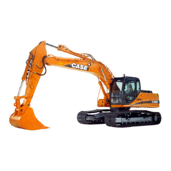
Where is the main hydraulic control shut off valve or solenoid on a 165 case excavator
1 comments:
Mr. Anderson
April 4, 2025
The main hydraulic control shut off solenoid (part of the swing brake and cushion systems) is located in the six-solenoid valve bank, which is in the pump compartment.
This answer is automatically generated
Thomas permenter
April 4, 2025
Main hydraulic is shut off by a safety switch location would be nice runs perfect. Stopped working machine for mayeby 30 minutes got back on and nothing hydraulic worked


Need help?
Do you have a question about the CX Series and is the answer not in the manual?
Questions and answers
Where is the main hydraulic control shut off valve or solenoid on a 165 case excavator
The main hydraulic control shut off solenoid (part of the swing brake and cushion systems) is located in the six-solenoid valve bank, which is in the pump compartment.
This answer is automatically generated
Main hydraulic is shut off by a safety switch location would be nice runs perfect. Stopped working machine for mayeby 30 minutes got back on and nothing hydraulic worked